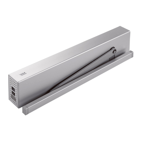
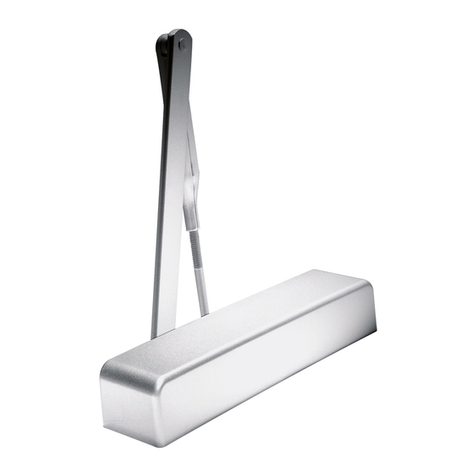
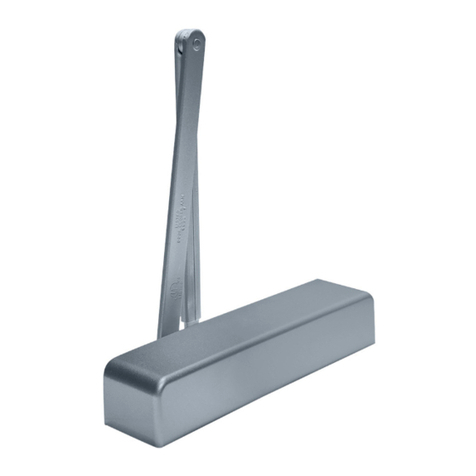
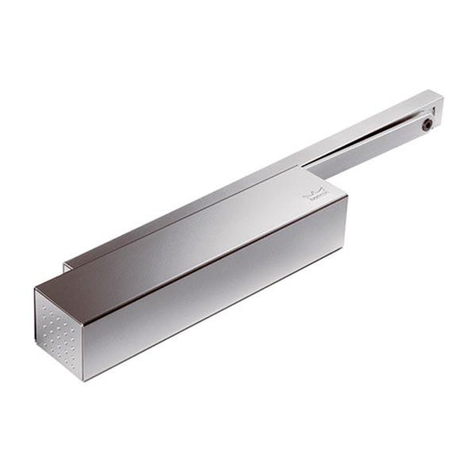
Dorma ED 100 User manual

Operating instructions
ED 100, ED 250
—

ED 100, ED 250
—
2DORMA
This instruction manual is designed for all those operating their
automatic door system with an ED 100 or ED 250.
It is intended for the person responsible for the technical maintenance
and reliable functioning of the door system.
Please read these instructions carefully and keep them readily to hand
within the close range of the door system.
Contents
Page
1. For your safety 2 - 3
2. EC declaration of conformity 4
3. EC declaration of incorpofration 4
4. System setup 5
5. Technical specifications 5
6. Functional characteristics 6 - 7
7. Malfunctions 7
8. Accessories 8
„Translation of original operating instructions”
1. For your safety
This documentation contains important information regard-
ing the mounting and the safe operation of the door system.
Read these instructions carefully before operating the
ED 100/250.
It is important for your personal safety to abide by all
enclosed instructions.
An incorrectly performed installation might cause serious
injuries.
Using control elements, making adjustments or performing
procedures that are not described in this documentation
might cause electric shocks, danger caused by electric
voltage/current and/or danger due to mechanical incidents.
Please keep these documents for further reference and hand
them over to the person in charge in case the system is
transferred to another party.
Explanation of symbols
NOTE This symbol underlines important infor-
mation that may facilitate your work.
REMARK This symbol warns you of possible system
damage and explains how to avoid this
damage.
WARNING This symbol indicates dangers that might
cause personal or material damage or
even kill people.
Intended application
As electromechanical swing door operators, the ED 100 and
the ED 250 are only designed to open and close interior
swing doors with a door-leaf weight of up to 100 and 250 kg
respectively.
Simply select the suitable version according to your prevailing
door-leaf width and weight.
Both operators are suitable for installation as pull-version
with ED slide channel set and as push-version with the
ED standard arm. The closing force paths have been
optimised for the respective ways of mounting and comply
with the requirements of EN 1154.
Limitation of liability
The ED 100/250 may only be used according to their
specified intended application. DORMA GmbH + Co. KG
will not accept any liability for damage resulting from
unauthorised modifications of the ED 100/250. Furthermore
components/accessories that have not been approved by
DORMA are exempted from liability.

ED 100, ED 250
—
3DORMA
Safety instructions
Work on electrical equipment may only be performed
by properly qualified staff (electricians).
• Do not allow children to play with the ED 100/250 or
its rigidly mounted adjustment and control devices.
• Keep remote controls out of reach of children.
• Never stick metal objects into the openings of the
ED 100/250; otherwise you might sustain an electric
shock.
• The ED 100/250 has to be secured against water and
other liquids.
• Only specially qualified staff may open the power
supply housing.
• Disconnect the ED 100/250 from power supply (de-
energise the system) before removing the cover of the
power supply housing.
Low-energy product
The ED 100/250 meets the requirements of a low-energy
application in accordance with the German DIN 18650
(industrial standard):
• Reduced dynamic force at door leaf and reduced
contact force via low driving speeds
• Reduced static force at door leaf and reduced contact
force via force limitation
The door system does not compulsorily require additional
safety equipment.
Dangers at closing edges
Automatic doors may cause hazards by crushing, shea-
ring, hitting and drawing-in at the different closing
edges.
Opposing closing edge
Secondary closing edge
Main closing edge
Dangers caused by slide channel and arm
The slide channel and the arm may cause hazards by
crushing and shearing.
Residual risk
Depending on the structural conditions, the prevailing door
version and the available safety equipment, residual risks
(such as crushing and hitting – with limited force) cannot be
excluded.
All people using a door are generally aware of the danger
spot at the secondary closing edge of every swing door (also
at manually operated doors).
This danger spot cannot be influenced by the manufacturer
of the operator and a protection of this closing edge often
cannot be realised due to its construction and technical
function.
A suitable clamping protection (like a rubber or textile cover)
is available in the specialised trade and not part of the scope
of delivery.
Recycling and disposal
Both the ED 100/250 and its packing mainly
consist of recyclable raw material.
The ED 100/250 and the respective accessories
must not be disposed of as domestic waste.
Please ensure that the old appliance and the
respective accessories (if available) are properly
disposed of.
Abide by the prevailing national statutory provisions!
Inspection and system approval
Before the first commissioning and depending on
requirements, however, at least once a year, the ED 100/250
has to be inspected by a properly qualified technician and
serviced if required.
A person trained by DORMA has to perform the inspection
and approve the system with the aid of the inspection book.
The respective results have to be documented in accordance
with DIN 18650-2 and the facility operator has to keep these
documents for at least one year.
We would recommend taking out a maintenance agree-
ment with DORMA.
Maintenance and Care
The system has to be de-energised/disconnected from power
supply before any kind of maintenance workor cleaning is
performed (switch off fuse).
You may clean the ED 100/250 with a damp cloth and
standard commercial detergents.
You should not use scouring agents for cleaning purposes as
they might damage the surface finish.
Wear
The following wear parts have to be inspected once a year
and replaced if required:
• Arm
• Slide shoe
• Slide channel
Only use original spare parts.

2. EC declaration of conformity
The undersigned representing the following manufacturer
DORMA GmbH + Co. KG
DORMA Platz 1
58256 Ennepetal
Germany
declares that the product
ED 100, ED 250
complies with the provisions of the EC Directive(s) specified in the Appendix and that the standards and/or technical specifi-
cations referred to in the Appendix were applied.
Richtlinie / Directive
X
2006/95/EG Niederspannungsrichtlinie / Low Voltage Directive / Directive basse tension
89/106/EWG/EEC/CEE Bauprodukte / Building products / Produits de construction
X2004/108/EG Elektromagnetische Verträglichkeit / Electromagnetic compatibility / Compatibilité électroma-
gnétique
2006/42/EG Maschinenrichtlinie / Machinery directive / Directive machine
Die technischen Unterlagen sind erhältlich beim Manager Productcompliance unter: /
The technical documentation is available from the Product Compliance Manager at: /
Les documents techniques sont disponibles auprès du Manager conformité produit à
Harmonisierte europäische Norm, nationale Regel / Harmonized European standard, national rule /
Norme européenne harmonisée, disposition nationale:
XEN 13849-1 XEN 61000 - 3 - 2 EN 179
EN ISO 12100 XEN 61000 - 3 - 3 EN 1125
XEN ISO 12100-1 EN 55014 EN 1154
XEN ISO 14121-1 XEN 55022 EN 1155
XBGR 232 XEN 60335 - 1 EN 1158
XEN 61000 - 6 - 2 XEN 60950 - 1 EN 1935
XEN 61000 - 6 - 3 EN 12209
3. EC declaration of incorpofration
The manufacturer
DORMA GmbH + Co. KG
DORMA Platz 1
58256 Ennepetal
Germany
declares that the incomplete machine
ED 100, ED 250
complies with the following basic requirements of the Machinery Directive (2006/42/EC) - Annex I, Section:
1.1.3, 1.1.5, 1.2.1, 1.2.3, 1.2.5, 1.2.6, 1.3.1, 1.3.2, 1.3.3, 1.3.4, 1.3.7, 1.3.8.1, 1.3.9, 1.5.1, 1.5.2, 1.5.4- 1.5.10,
1.5.16, 1.6.1, 1.6.2, 1.6.3, 1.6.4, 1.7.1.1, 1.7.3, 1.7.4
The incomplete machine further complies with all relevant provisions of Directives 2006/95/EC and 2004/108/EC.
It may be incorporated and operated in automatic door control mechanisms in conformity with the Machinery Directive pro-
vided that the manufacturer of the systems ensures that all requirements under the Machinery Directive are met and an EC
Declaration of Conformity has been issued.
The specific technical documentation was prepared and is available from the Product Compliance Manager at product.
complia[email protected].
It will be electronically forwarded to individual public authorities in response to a duly reasoned request.
ED 100, ED 250
—
4DORMA

35
10
9876
5
43
21
1211
13
ED 100, ED 250
—
5DORMA
4. System setup
Operator system
The operator system comprises all core components.
Select the system in accordance with the door-leaf width and the door-leaf weight.
1. Mains connection
2. Connection unit
3. Axle connection on both sides
4. Drive system (motor/gear/ spring)
5. Adjustment of closing force
6. Control unit
7. Switching power supply unit
8. Slot for DORMA Upgrade Cards
9. User interface with information display
10. Internal program switch
11. * Slide channel (Set)
12. * Standard arm
13. * Complete cover
* Not part of the scope of delivery.
5. Technical specifications
Required operating conditions
Ambient temperature -15 to +50° C
Only suitable for dry environments relative humidity max. 93%, non-condensing
Power supply 230 V AC +/- 10% 50 Hz
Power consumption for external accessories Max. 1500 mA
General specifications
Dimensions (WxHxD) 685 x 70 x 130 mm
Operator weight 12 kg
Power supply for external accessories 24 V DC +/- 10%, 1.5 A
ED 100
Power consumption Max. 120 Watts
Closing force EN 1154 EN 2-4, adjustable (Fire protection from EN 3 on)
Opening speed* Max. 50° / second
Closing speed* Max. 50° / second
ED 250
Power consumption Max. 240 Watts
Closing force EN 1154 EN 4-6, adjustable
Opening speed* Max. 60° / second
Closing speed* Max. 60 / second

ED 100, ED 250
—
6DORMA
6. Functional characteristics
DORMA ED 100 and ED 250 are electromechanical swing
door operators and suitable for various fields of application.
Select the respective version depending on the prevailing
door-leaf width and the door weight.
While the ED 100 is suitable for doors with a weight of up to
100 kg and a door width of 1,100 mm, the ED 250 is desi-
gned for doors with a width of 1,600 mm (1,400 mm when
installed at fire and smoke doors) and a door weight
of 250 kg.
Both operators may be installed as push-version with stan-
dard arm and as pull-version with slide channel.
All these variants are suitable for application at fire and
smoke doors.
The swing door operator opens the door automatically as
soon as an activator has been triggered.
In case a suitable locking device is installed, it will be unlo-
cked before the door starts to move.
The adjusted hold-open time starts as soon as the door is
open and the door closes automatically on expiry of the
adjusted time.
Users may access the door manually at any time. In this case
the operator has the function of a common door closer.
Switches
The mains switch is always installed on the side of the door
hinge, while the internal program switch is always installed
on the side of the main closing edge. The external program
switch is mounted within the close range of the door.
5
4
3
2
1
1
24
3
2
35
4
1
Mains switch Program switch
Power supply internal Program switch
external Program switch
OFF
AUTOMATIC
EXIT ONLY
PERMANENT
OPEN
without Function
MALFUNCTION
Program switch
The program switch may be installed internally or externally
and is available in a 4-position and a 3-position version.
The 3-position program switch does not offer an EXIT ONLY
function.
Functions
OFF The door opens automatically when the
Night-/Bank activator is triggered and closes
on expiry of the Night-/Bank hold-open time.
AUTOMATIC The door opens automatically when one of
the activators is triggered and closes on
expiry of the adjusted hold-open time.
PERMANENT The door opens automatically and
OPEN remains open until the function is deactiva-
ted.
EXIT ONLY The door only opens automatically after the
internal activator or the Night-/Bank activator
has been activated. The door closes on expiry
of the adjusted hold-open time.
Selection of functions
Activate the desired function by pushing the respective key
on the external program switch (see picture at the bottom of
the left column).
When performing adjustments with the aid of the internal
program switch, you have to adjust both switches in a certain
combination:
The front switch is only adjusted to "I"if you want to adjust
the EXIT ONLY function.
OFF
Adjust both switches to "0".
AUTOMATIC
Adjust the front switch to "0",
and the other switch to "I".
PERMANENT OPEN
Adjust the front switch to "0",
and the other switch to "II".
EXIT ONLY
Adjust the front switch to "I",
and the other switch to "I".

ED 100, ED 250
—
7DORMA
Activators
Internal and external activators, a Night-/Bank activator and
an intercommunication system may be connected to the door
system. The internal activator is normally installed inside the
building or room while the external activator is installed on
the outside of the building or room. A Night-/Bank activator
is mounted on the outside and often realised as card reader
or key switch.
Manual locking device
When the door is locked by hand:
• The operator must be adjusted to OFF in order to avoid
damage to the door system.
• If a lock switch is installed, the operator will be
switched off automatically.
DORMA recommends installing a lock switch.
Safety equipment
The required safety equipment in accordance with
the latest state of the common and country-specific
standards, laws, codes and regulations has to be
installed before the system is mounted.
The ED 100 and ED 250 operators may be used in a low-
energy-mode and a full-energy-mode.
Low-Energy-Mode
The low driving speed of the door avoids dangers resulting
from the automatic movement of the door as far as possible.
The door opens at an extremely low speed and thus offers a
high safety level.
7. Malfunctions
Malfunctions may have different reasons.
Ambient conditions often cause malfunctions, thus the
operator tries to analyse these conditions and to respond
correspondingly. In this case the operator interrupts its
currently adjusted function and restarts following a certain
standby-time or when a new pulse has been triggered. In
case this fails, the automatic function of the operator is
switched off and the system displays an error message.
A red LED at the program switch indicates the malfunction.
The LED either blinks or shows a continuous light and
thereby indicates that the malfunction has to be removed by
DORMA Service.
Self-help in case of malfunctions
You have the following options to reset error messages:
1. Set program switch to OFF or reset the system with
the aid of the RESET key on the user interface while
the cover is open.
2. Mains reset: Set mains switch to OFF; then wait for 10
seconds and set it back to ON position.
Always analyse and remove the cause for the malfunction
before you acknowledge the respective error message.
Full-Energy-Mode
Due to the high driving speed of the door, the swing path has
to be protected with the aid of sensors.
Safety sensors that are mounted to the door leaf monitor the
swing path and thus avoids that people are hit by the door as
far as possible.
Safety sensors on hinge side
In case an obstruction is detected within the detection range
of the safety sensors:
• The door stops during its opening cycle
• The door remains closed (does not perform an opening
cycle) if the door is in “closed“ position.
The operator will resume standard operation as soon as the
detection range is no longer obstructed.
Safety sensors on opposite hinge side
In case an obstruction is detected within the detection range
of the safety sensors:
• The door will reverse during the closing cycle
• The door will remain open.
The operator will resume standard operation as soon as the
detection range is no longer obstructed.
Maintenance interval indicator
In case you have installed the internal 4-position program
switch, you will have a maintenance interval indicator. A
yellow LED informs you that the system has to be serviced.
DORMA Service may adjust the maintenance interval
indicators.
The following table is designed for you assistance.
Please check the following questions in case the door still
does not close or open:
• Is the power supply available?
• Is the mains switch adjusted to ON?
• Is the door freely movable?
• Is the door locked manually? Has the lock switch been
activated?
• Is the program switch properly adjusted (correct
position)?
• Is the swing path unobstructed?
• Has the hold-open device been triggered?
In case you have checked all the above-mentioned questions
and the system still does not work, please contact DORMA
Service to remove the malfunction.
ED 100, ED 250
—
8DORMA
8. Accessories
Electrical connection
Apart from the broad range of DORMA accessories, also
other manufacturers offer various activators, locking devices,
safety sensors and further accessories that are compatible
with ED 100 and ED 250 operators. All accessories that are
approved by DORMA for application at ED 100 and ED 250
operators are listed on the positive list for accessories.
www.dorma.com/positivliste
DORMA cannot ensure the compatibility of devices that are
not listed on the positive list. If these components are used
nonetheless, it might happen that the full range of functions
is not available or that the operator works improperly.
Furthermore the operator or the connected component might
be damaged.
See limitation of liability on page 3.
Activator
In general we refer to the following devices as activators:
• Radar motion detectors
• Passive infrared motion detectors
• Pushbuttons
• Switches
• Sensors
• Radio systems, infrared receivers
• Access control systems
• Telephone systems and intercoms
Minimum requirements
Operating voltage with power supply via operator:
24 V DC +/- 10%
Pulse width:
min. 200 ms
Potential-free output
(When installed at internal signal input, external
detector or Night-/Bank)
Energised output (telephone systems):
8 - 24 V DC / AC + 10%
Locking device
In general we refer to the following devices as locking
devices:
• Electric strike plate
• Electric strikes Motor locks with feedback contact
• Multi-point locking device with feedback contact
• Door magnets
Motor locks/multi-point locking devices without feedback
contact cannot be directly connected to the operator. In
order to ensure that the operator and the locking device work
together properly, the locking device has to comply with the
following specifications:
Minimum requirements
Operating voltage with power supply via operator:
24 V DC +/- 10%
Operating voltage with external power supply:
max. 48 V DC/AC
Current load for relay contact of locking device:
max. 1 A
Rated for continuous duty: electric strike:
min. 30%
Rated for continuous duty: motor lock:
100 %

ED 100, ED 250
—
9DORMA

ED 100, ED 250
—
10 DORMA

ED 100, ED 250
—
11DORMA

WN 058176 45532, 07/13, Subject to change without notice
DORMA GmbH + Co. KG
DORMA Platz 1
58256 ENNEPETAL
GERMANY
Tel. +49 2333 793-0
Fax +49 2333 793-4950
www.dorma.com
Other manuals for ED 100
5
This manual suits for next models
2
Table of contents
Other Dorma Door Opening System manuals

Dorma
Dorma ES 200 Easy User guide

Dorma
Dorma 8900 PT User manual

Dorma
Dorma 8916 TDE User manual

Dorma
Dorma G-SR EMR User manual

Dorma
Dorma 8600 EMR Series User manual

Dorma
Dorma Manet User guide

Dorma
Dorma 7400 TDE User manual

Dorma
Dorma ED400 User guide

Dorma
Dorma ES 200 User manual

Dorma
Dorma 9800FL Series User manual
Popular Door Opening System manuals by other brands

Tyco
Tyco MC-309 PG2 installation instructions

Dormakaba
Dormakaba TS 98 XEA manual

Entrematic
Entrematic Ditec DODSBC quick guide

Entrematic
Entrematic EM EMSW EMO Service manual

Entrematic
Entrematic Ditec VALLOKA installation manual

Keyautomation
Keyautomation LEV3281LT Instructions and warnings for installation and use