manuals.online logo
Brands
  1. Home
  2. •
  3. Brands
  4. •
  5. Dorma
  6. •
  7. Door Opening System
  8. •
  9. Dorma MUTO COMFORT L 80 User manual

Dorma MUTO COMFORT L 80 User manual

Other Dorma Door Opening System manuals

Dorma PT 51 User manual

Dorma

Dorma PT 51 User manual

Dorma COMFORTDRIVE Moveo User manual

Dorma

Dorma COMFORTDRIVE Moveo User manual

Dorma EM User manual

Dorma

Dorma EM User manual

Dorma 8616 AFMJ User manual

Dorma

Dorma 8616 AFMJ User manual

Dorma AGILE 150 Installation guide

Dorma

Dorma AGILE 150 Installation guide

Dorma 7300 ARNP User manual

Dorma

Dorma 7300 ARNP User manual

Dorma 8616 ARNP User manual

Dorma

Dorma 8616 ARNP User manual

Dorma ITS 96 Manual

Dorma

Dorma ITS 96 Manual

Dorma 8616 FH User manual

Dorma

Dorma 8616 FH User manual

Dorma EM 508 Series User manual

Dorma

Dorma EM 508 Series User manual

Dorma 8900 DS User manual

Dorma

Dorma 8900 DS User manual

Dorma AGILE 150 User manual

Dorma

Dorma AGILE 150 User manual

Dorma 8916 AF89 PFT User manual

Dorma

Dorma 8916 AF89 PFT User manual

Dorma 8916 AF8MJ User manual

Dorma

Dorma 8916 AF8MJ User manual

Dorma G-SR EMR Manual

Dorma

Dorma G-SR EMR Manual

Dorma AGILE 150 User manual

Dorma

Dorma AGILE 150 User manual

Dorma EMR Series User manual

Dorma

Dorma EMR Series User manual

Dorma 7400 DS User manual

Dorma

Dorma 7400 DS User manual

Dorma UNIVERSAL ARCOS User manual

Dorma

Dorma UNIVERSAL ARCOS User manual

Dorma 9600 Series User manual

Dorma

Dorma 9600 Series User manual

Dorma ES 410 User manual

Dorma

Dorma ES 410 User manual

Dorma ED800 J User manual

Dorma

Dorma ED800 J User manual

Dorma 7300 Series User manual

Dorma

Dorma 7300 Series User manual

Dorma PORTEO Guide

Dorma

Dorma PORTEO Guide

Popular Door Opening System manuals by other brands

Mobeye Call-Key MCK100 installation manual

Mobeye

Mobeye Call-Key MCK100 installation manual

SALICE Lapis Assembly instructions

SALICE

SALICE Lapis Assembly instructions

Cal-Royal N-F77CVR Installation instruction

Cal-Royal

Cal-Royal N-F77CVR Installation instruction

Scrigno OPEN1000 Assembly manual

Scrigno

Scrigno OPEN1000 Assembly manual

BFT WIND RMB 130B 200 installation manual

BFT

BFT WIND RMB 130B 200 installation manual

Alecto ADI-250 user manual

Alecto

Alecto ADI-250 user manual

Besam Swingmaster MP Installation, adjustment and maintenance instructions

Besam

Besam Swingmaster MP Installation, adjustment and maintenance instructions

Assa Abloy SARGENT 1431 Series instructions

Assa Abloy

Assa Abloy SARGENT 1431 Series instructions

GAL MOVFR Quick setup

GAL

GAL MOVFR Quick setup

Häfele Finetta T 70 VF manual

Häfele

Häfele Finetta T 70 VF manual

AGS D-PL Instructions for fitting, operating and maintenance

AGS

AGS D-PL Instructions for fitting, operating and maintenance

Stanley MA900ñ Installation and owner's manual

Stanley

Stanley MA900ñ Installation and owner's manual

WITTUR Hydra Plus UD300 Instruction handbook

WITTUR

WITTUR Hydra Plus UD300 Instruction handbook

Alutech TR-3019-230E-ICU Assembly and operation manual

Alutech

Alutech TR-3019-230E-ICU Assembly and operation manual

Pamex KT-INP35 Installation instruction

Pamex

Pamex KT-INP35 Installation instruction

MPC ATD ACTUATOR 50 ATD-313186 Operating and OPERATING AND INSTALLATION Manual

MPC

MPC ATD ACTUATOR 50 ATD-313186 Operating and OPERATING AND INSTALLATION Manual

Chamberlain T user guide

Chamberlain

Chamberlain T user guide

Fireco Dorgard operating guide

Fireco

Fireco Dorgard operating guide

manuals.online logo
manuals.online logoBrands
  • About & Mission
  • Contact us
  • Privacy Policy
  • Terms and Conditions

Copyright 2025 Manuals.Online. All Rights Reserved.

MUTO COMFORT
L 80
—
Montageanleitung
Mounting instructions
Instrucciones de montaje
Notice de pose
Istruzioni per il montaggio
Инструкция по монтажу
Allgemeine Informationen über Anleitung und Produkt (DE)
General information about the instructions and the product (EN)
Información general del producto e instrucciones de montaje (ES)
Informations générales sur les instructions de montage et le produit (FR)
Informazioni generali relative alle istruzioni di prodotto (IT)
Общая информация о продукте и настоящем руководстве (RU)
4-5
6-7
8-9
10-11
12-13
14-15
Lieferumfang (DE)
Scope of delivery (EN)
Volumen de suministro (ES)
Étendue de la livraison (FR)
Dotazione (IT)
Комплект поставки (RU)
16
Wandmontage (DE)
Wall mounting (EN)
Montaje en la pared (ES)
Pose murale (FR)
Montaggio a parete (IT)
Крепление к стене (RU)
17-28
Montage ohne DORMOTION (DE)
Installation without DORMOTION (EN)
Montaje sin DORMOTION (ES)
Variante sans DORMOTION (FR)
Variante senza DORMOTION (IT)
Без функции DORMOTION (RU)
29
Ausführungsvariante an Decke (DE)
Version at ceiling (EN)
Montaje a techo (ES)
Variante au plafond (FR)
Versione a soffitto (IT)
Крепление к потолку (RU)
30-31
MUTO COMFORT L 80
—
2
Ausführungsvariante mit einem Seitenteil (DE)
Ausführungsvariante zwischen zwei Wänden/in Laibung (DE)
Version with side panel (EN)
Version between two walls/in a door jamb (EN)
Variante de ejecución vidrio lateral (ES)
Montaje entre dos paredes / fijado al marco de puerta (ES)
Variante avec fixe latéral (FR)
Variante entre deux murs / sous linteau (FR)
Variante di montaggio con elemento affiancato (IT)
Versione chiusura vano murario (IT)
Вариант комплектации с боковой панелью (RU)
Крепление в проём (RU)
32-36
Ausführungsvariante mit zwei Seitenteilen und Sichtschutzprofil (DE)
Version with two side panels and view protection profile (EN)
Montaje con dos fijos laterales con perfil de protección visual (ES)
Variante avec deux fixes latéraux et profilé d'occultation (FR)
Versione con due pannelli laterali e profile di protezione (IT)
Вариант комплектации с двумя боковыми панелями и декоративным профилем (RU)
37-39
Ausführungsvariante für abgehängte Decke (DE)
Version for false ceiling (EN)
Montaje en falso techo (ES)
Variante pour plafond suspendu (FR)
Versione per controsoffitto (IT)
Вариант комплектации для стыковки с фальш-потолком (RU)
40-41
Ausführungsvariante an Glaswand (DE)
Version on glass wall (EN)
Variante de ejecución en frente de vidrio (ES)
Variante sur cloison en verre (FR)
Variante di esecuzione su parete in vetro (IT)
Вариант комплектации для установки на стекло (RU)
42-43
Ausführungsvariante Holztürflügel (DE)
Version with wood panel door (EN)
Variante de ejecución para puerta de madera (ES)
Variante ave00c vantail bois (FR)
Variante del modello per anta in legno (IT)
Вариант комплектации с деревянной панелью (RU)
44-45
MUTO COMFORT L 80
—
3
MUTO COMFORT L 80
—
4
Sicherheitshinweise
- Montage muss von zwei Personen ausgeführt werden
- Schutzkleidung tragen
Bestimmungsgemäße Verwendung
- nur für Schiebetüren im trockenen Innenbereich
- nur für manuelles langsames Öffnen und Schließen
Anforderung Wand/Decke und Befestigungsmaterial
- Die Unterkonstruktion/Wand muss dauerhaft tragfähig,
plan und lotrecht sein (max. Toleranz: 2 mm pro Meter).
- Das Befestigungsmaterial muss für die Unterkonstruktion /
Wand geeignet und für das Türflügelgewicht ausreichend
dimensioniert sein. Beachten Sie die technischen Hinweise
des Befestigungsmaterials.
- Befestigungsmaterial ist nicht im Lieferumfang enthalten.
Anforderungen Glastürflügel:
- heißgelagertes Einscheibensicherheitsglas
(ESG-H nach DIN EN 12150-1)
- Klemmbereich muss plan und unbeschichtet sein
(keine selbstreinigenden Beschichtungen!)
Wartung, Pflege, Reparatur
- mind. 5 Jahre wartungsfreier Betrieb
(bei 50 Betätigungen pro Tag)
- beschädigte Bauteile unverzüglich austauschen
- nur DORMA-Originalteile verwenden
- gelegentliche Reinigung, insbesondere der Lauffläche,
nur mit feuchtem Tuch
Entsorgung
Die ordnungsgemäße Entsorgung unterliegt den geltenden
nationalen gesetzlichen Vorschriften.
Funktionsweise dieser Anleitung
Die Montage jeder Ausführungsvariante (z. B. Wand, Decke,
mit Seitenteil) ist separat beschrieben. Montieren Sie die
Anlage wie in dem entsprechenden Kapitel der Anleitung
beschrieben.
Über diese Anleitung
Diese Anleitung beschreibt die Montage des
Schiebetürsystems MUTO Comfort L 80 mit DORMOTION. Die
Montage wird am Beispiel einer linksöffnenden Tür gezeigt.
Die Montage für rechtsöffnende Türen erfolgt entsprechend
spiegelbildlich.
Zielgruppe
DORMA-Glasbeschläge dürfen nur von Fachpersonal montiert
werden.
Verwendete Symbole – Sicherheit
Vorsicht!
Befestigungsmaterial muss den Anforderungen
von Unterkonstruktion/Wand und Türflügelgewicht
entsprechen. Beachten Sie die technischen Hinweise
des Befestigungsmaterials.
Vorsicht Glasbruch
Bei Einhängen des Türflügels müssen Holzklötze
oder ähnliches untergelegt werden.
Vorsicht Verletzung durch Quetschen!
Fangpuffer so positionieren, dass Türgriffe (Option)
mindestens 25 mm Abstand zur Wand einhalten.
Nur silikon- und ölfreie Reiniger verwenden
(z. B. Aceton).
Verwendete Symbole – Montage
Texthinweis beachten
A
Verweis auf Montageschritte
für Ausführungsvarianten
(Beispiel zeigt: Holzflügel, Schritt 2)
Zweiflügelige Schiebetür
12Reihenfolge der Montageschritte
12Einzelschritte innerhalb eines Montageschrittes
Schließkante
ORIGINALANLEITUNG
VOR GEBRAUCH SORGFÄLTIG LESEN
AUFBEWAHREN FÜR SPÄTERES
NACHSCHLAGEN
DE
Änderungen vorbehalten
A
A
2
MUTO COMFORT L 80
—
5
max. Türflügelbreite [mm]
Türflügelglasdicke [mm]
Türflügelgewicht [kg]
Glasdicke Festverglasung [mm]
Glasseitenteildicke
2000
8-13,5
< 80
10-19
8-13,5
2x 1250
8-13,5
2x < 80
10-19
8-13,5
max. Türflügelbreite [mm]
Holzflügeldicke [mm]
Türflügelgewicht [kg]
2000
28-50
< 80
2x 1250
28-50
2x < 80
Lieferumfang
Technische Daten
1Abdeckprofil
2Sichtschutzbürste (in zwei Ausführungen)
3
Glaskantenschutz bei Anschlag Türflügel-Wand
oder Türflügel-Türflügel
4
Bodenführungsset für Glastürflügel
mit Einstellmöglichkeit der Glasführung
5
DORMOTION-Einheiten - optional
6
Rollenwagen
7
DORMOTION-Starter - optional
8
Haltereinsatz für Abdeckprofil
9Laufschiene
10 Fangpuffer zur Begrenzung des Anschlags
Türflügels beim Öffnen und Schließen
11 Endkappe
12 Abstandshalter für Abdeckprofil
13
Stirnabdeckung
14
Seitenteilprofil
15
Verglasungsdichtung (in drei Ausführungen)
16
Zwischenlage
17
Füllprofil
18
Glasanlageprofil
19
Glasaufnahme Boden
20
Sichtschutzprofil
21
Halterclips
22
Profil für abgehängte Decke
23
Stirnabdeckung
24
Gegenhalteprofil
25
Halteplatten
26
Holzadapter für Rollenwagen
27
Bodenführungsset für Holztürflügel
MUTO COMFORT L 80
—
6
Safety instructions
- Installation requires two people
- Always wear protective clothing
Intended use
- for sliding doors in dry indoor areas only
- for manual slow opening and closing only, door leaf
must be stopped manually before reaching end position
Wall/Ceiling requirements and fittings
- The substructure/wall must be able to bear permanent loads,
be level and perpendicular (max. tolerance: 2 mm per meter).
- Fittings must be sufficiently dimensioned for the substructure/
wall and for the weight of the door. Please read the technical
information for fittings.
- Fittings are not included.
Requirements for glass panel:
- Heat-soaked thermally toughened safety glass
(ESG-H in compliance with DIN EN 12150-1)
Clamping area must be level and uncoated
(no self-cleaning coating!)
Maintenance, care, repair
- minimum of 5 years maintenance-free operation
(based on 50 cycles per day)
- immediately replace damaged parts
- always use original DORMA parts
- use a damp cloth for occasional cleaning especially of the
track
Disposal
Dispose in accordance with national regulations.
Functionality of this manual
The mounting of each different version (e.g. wall, ceiling,
with side panel) is described separately. Mount the system as
described in the respective chapter of your manual.
Regarding these instructions
These instructions describe the mounting of the sliding door
system MUTO Comfort L 80 with DORMOTION. These instruc-
tions describe the installation of a left hand door. Use mirror
image for a right hand door.
Target group
Only properly qualified staff is authorized to mount DORMA
glass fittings.
Symbols used – Safety
Caution!
Fittings must meet the requirements of substructure/
wall and door weight. Please read the technical
information for fittings.
Risk of breaking glass
When fitting the door, support the panel with a block
of wood or similar object.
Risk of crushing!
Position buffer stop so door handles (optional) are at
least 25 mm away from the wall.
Always use silicone- and oil-free cleaners
(e.g. acetone).
Symbols used – Installation
Read notes
A
Reference to deviating installation steps
for different versions
(Example here: wood panel, step 2)
Two-leaf sliding door
12Installation sequence
12Individual steps within an installation step
Closing edge
Closing edge
ORIGINAL INSTRUCTIONS
READ CAREFULLY BEFORE USE
KEEP SAFE FOR
FUTURE REFERENCE
EN
Subject to change without notice
A
A
2
MUTO COMFORT L 80
—
7
Scope of delivery
Technical data
1Cover panel
2Brush strip (in two versions)
3
Glass edge protector for door leaf/wall or door
leaf/door leaf end stop
4
Floor guide kit for glass door leaf
with glass guide adjustment option
5DORMOTION unit - optional
6
Roller carriage
7
DORMOTION starter - optional
8
Bracket insert for cover panel
9Track
10 Buffer stop to limit door travel
when opening and closing
11 End cap
12 Cover spacer
13
End cover
14
Side section panel
15
Glazing seal (in three versions)
16
Pad
17
Filler panel
18
Glass connecting pad
19
Bottom glass slot
20
View Protection Profile
21
Retaining Clips
22
Connecting profile for false ceiling
23
End cover
24
Counter panel
25
Retaining plates
26
Wood adapter for roller carriage
27
Floor guide kit for wooden door leaf
Max. door leaf width [mm]
Door leaf glass thickness [mm]
Door leaf weight [kg]
Glass thickness fixed glazing [mm]
Glass side panel thickness
2000
8-13.5
< 80
10-19
8-13.5
2x 1250
8-13.5
2x < 80
10-19
8-13.5
Max. door leaf width [mm]
Wood leaf thickness [mm]
Door leaf weight [kg]
2000
28-50
< 80
2x 1250
28-50
2x < 80
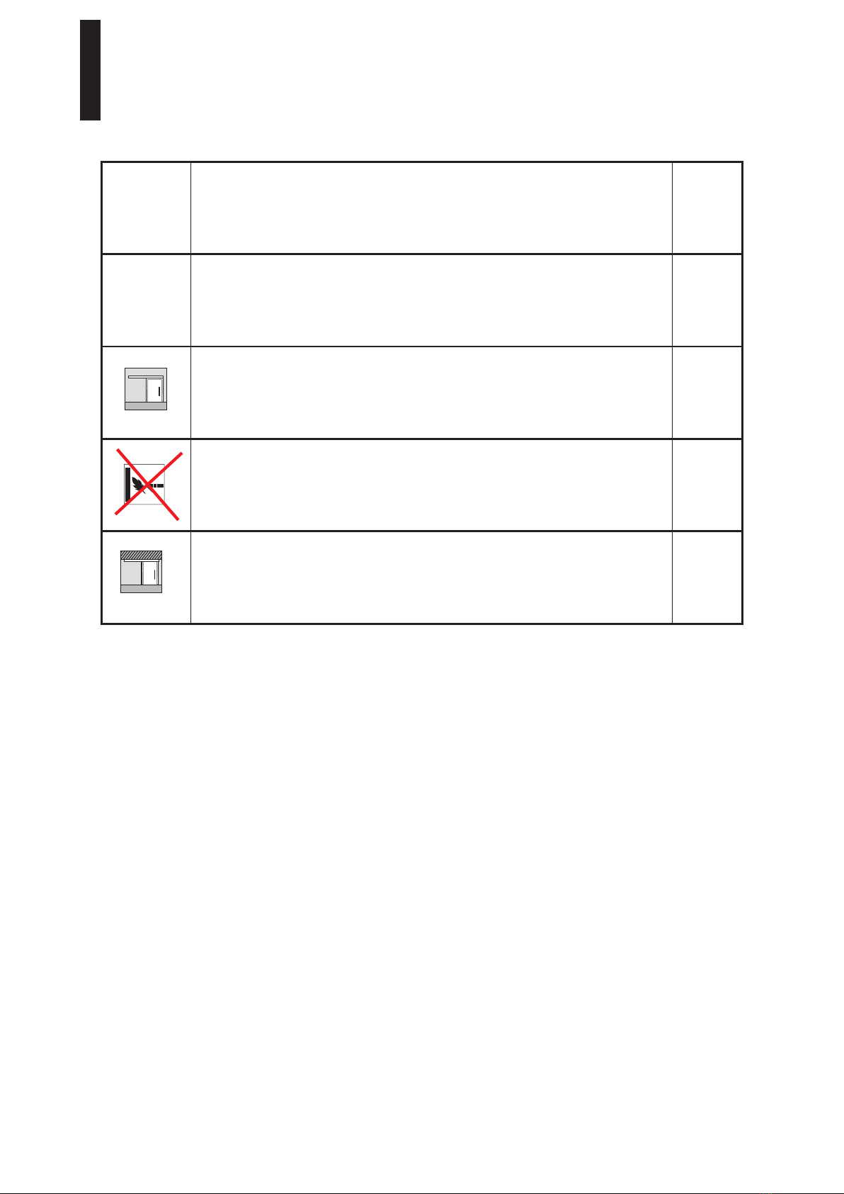
Indicaciones de seguridad
- El montaje debe ser realizado por dos personas.
- Llevar ropa de protección
Uso conforme a lo previsto
- Solo para puertas correderas en interiores secos.
- Solo para abrir y cerrar lentamente a mano; la hoja de la
puerta se debe detener a mano antes de alcanzar la
posición final.
Requerimiento de la pared/el techo y material de fijación
- La subestructura/pared debe contar con capacidad de carga
permanente y ser plana y perpendicular
(tolerancia máx.: 2 mm por metro).
- El material de fijación debe ser adecuado para la subestructu-
ra/pared, y estar suficientemente dimensionado para el peso
de las hojas de la puerta. Observe las indicaciones técnicas
del material de fijación.
- El material de fijación no está incluido.
Requerimientos de las puerta de vidrio:
- Vidrio de seguridad monocapa templado
(ESG-H según DIN EN 12150-1).
- La zona de sujeción debe ser plana y sin revestir
(¡sin revestimientos autolimpiantes!).
Mantenimiento, cuidado y reparación
- Funcionamiento libre de mantenimiento durante al menos
5 años (con 50 accionamientos al día).
- Sustituir de inmediato los componentes dañados.
- Usar únicamente piezas originales de DORMA.
- Limpieza ocasional, en particular de la superficie de
deslizamiento, solo con un paño húmedo.
Disposición
La eliminación o cambio de las normas está sujeta a los
requisitos legales en vigor de cada pais.
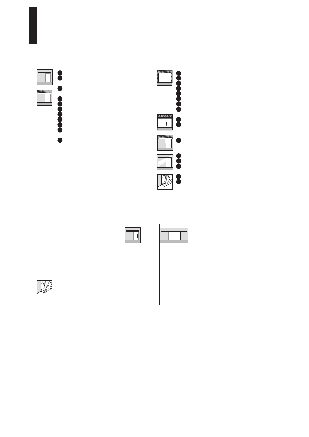
Funcioalidad de este manual
El montaje para cada version es diferente ( ejemp. pared,
techo con vidrio lateral ) y se describen por separado. Por
favor monte el sistema como se describe en el capitulo
correspondiente del manual.
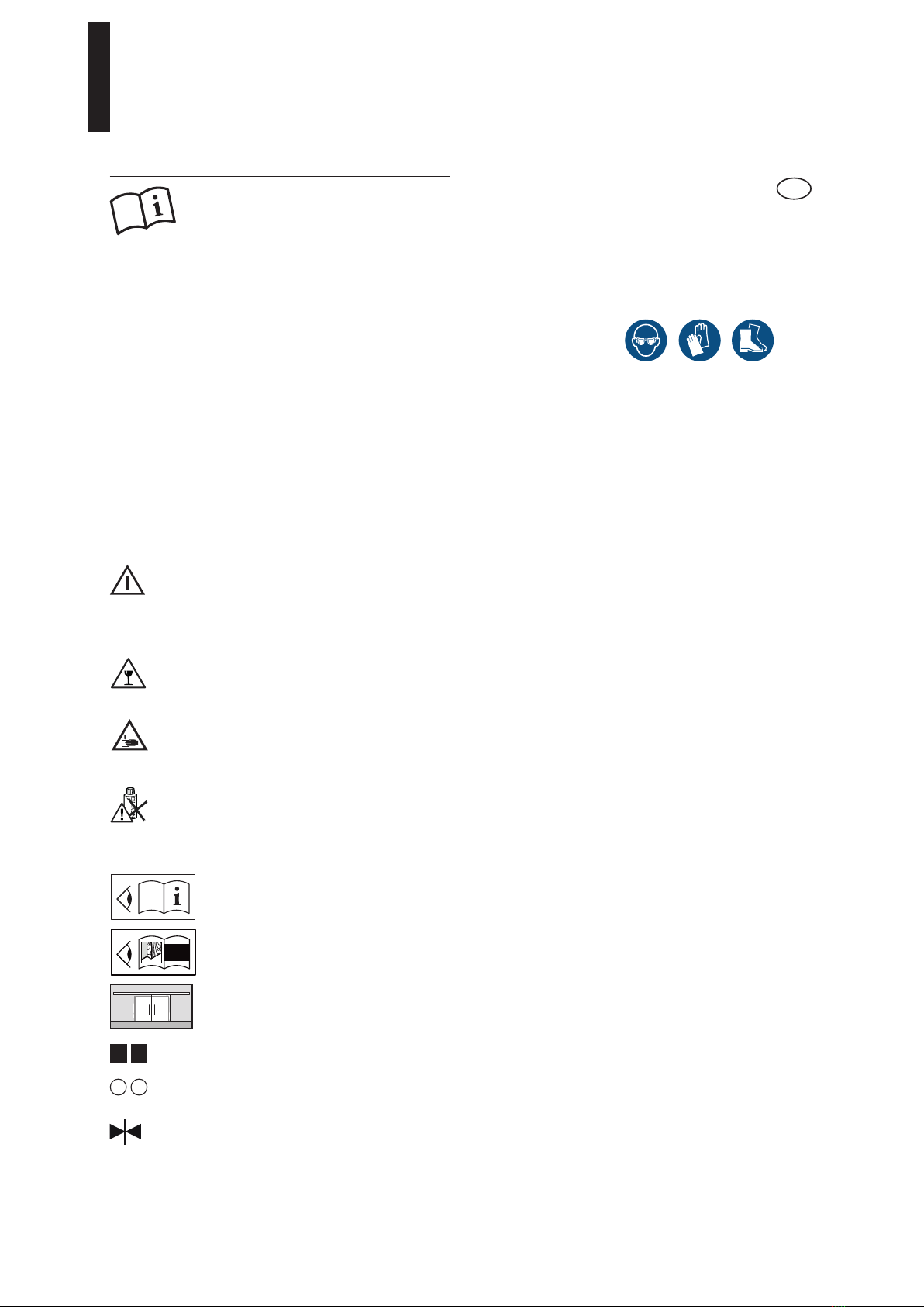
Acerca de estas instrucciones
Estas instrucciones describen el montaje del sistema de
puerta corredera MUTO Comfort L 80 con DORMOTION.
Estas instrucciones describen la instalación de una puerta de
mano izquierda.
Grupo designado
El montaje de los herrajes de vidrio debe llevarlo a cabo
personal cualificado y que esté especialmente formado para
instalar vidrios.
Símbolos utilizados. Seguridad
¡Atención!
El material de fijación debe cumplir los
requerimientos de la subestructura/pared y del
peso de las hojas de la puerta. Observe las
indicaciones técnicas del material de fijación.
¡Atención! ¡Riesgo de rotura de vidrios!
Al colgar la hoja de la puerta se deben colocar debajo
tacos de madera u otros objetos similares.
¡Atención! ¡Lesiones por aplastamiento!
Posicionar el amortiguador de modo que los tiradores
de la puerta (opcionales) queden a una distancia
mínima de 25 mm de la pared.
Usar únicamente limpiadores sin silicona ni aceite
(p. ej. acetona).
Símbolos utilizados. Montaje
Observar las notas
A
Referencia sobre pasos de montaje distintos
para variantes de ejecución
(en el ejemplo: hoja de madera, paso 2)
Puerta corredera de dos hojas
12Orden de los pasos de montaje
12Pasos individuales dentro de un paso de montaje
Canto de cierre
Traducción de las instrucciones originales
LEER ATENTAMENTE ANTES DE USAR
CONSERVAR PARA CONSULTAS
POSTERIORES
ES
MUTO COMFORT L 80
—
8
Modificaciones reservadas
A
A
2
Volumen de suministro
Especificaciones técnicas
1Perfil tapa
2Cepillo de protección visual
(en dos ejecuciones)
3Protección de canto del vidrio
(tope puerta-pared o puerta-puerta)
4Guia de suelo "regulable" para puerta de vidrio
5Unidad DORMOTION - Opcional
6
Patín de rodillos
7
Iniciador DORMOTION - Opcional
8
Soporte para perfil tapa
9Carril guía deslizante
10 Amortiguador para limitar el tope de la hoja de
la puerta durante la apertura y el cierre
11 Tapa lateral
12 Separadores tapa
13
Cubierta frontal
14
Perfil de lateral
15
Junta de acristalamiento (en tres ejecuciones)
16
Pieza intermedia
17
Perfil de relleno
18
Perfil de colocación del vidrio
19
Alojamiento de vidrio en suelo
20
Perfil de protección visual
21
Clips de sujección
22
Perfil de conexión para falso techo
23
Cubierta frontal
24
Contraperfil
25
Placas de retención
26
Adaptador para madera, para patín de rodillos
27
Guía de suelo para puerta de madera
MUTO COMFORT L 80
—
9
Máx. anchura hoja de puerta [mm]
Espesor puerta de vidrio [mm]
Peso hoja de puerta [kg]
Espesor del vidrio fijo [mm]
Espesor del vidrio lateral
2000
8-13,5
< 80
10-19
8-13,5
2x 1250
8-13,5
2x < 80
10-19
8-13,5
Máx. anchura hoja de puerta [mm]
Espesor puerta de madera [mm]
Peso hoja de puerta [kg]
2000
28-50
< 80
2x 1250
28-50
2x < 80
MUTO COMFORT L 80
—
10
Consignes de sécurité
- La pose doit être effectuée par deux personnes
- Porter un équipement de protection
Utilisation conforme à l'usage prévu
- uniquement pour les portes coulissantes dans les
espaces intérieurs secs
- uniquement pour une ouverture et une fermeture lentes ; le
vantail doit être stoppé à la main avant d'atteindre
sa position finale
Critères exigés du mur/plafond et du matériel de fixation
- La sous-construction/paroi doit avoir une capacité de charge
durable, être plane et verticale
(tolérance max. : 2 mm par mètre).
- Le matériel de fixation doit être approprié pour la sous-
construction/mur et suffisamment dimensionné pour le poids
du vantail. Observez les consignes techniques relatives au
matériel de fixation.
- Le matériel de fixation ne fait pas partie de l'étendue de
la livraison.
Critères exigés pour le vantail en verre :
- verre de sécurité monovitre trempé à chaud
(ESG-H selon DIN EN 12150-1)
- la zone de serrage doit être plane et sans revêtement
(pas de revêtement autonettoyant) !
Entretien, maintenance, réparation
- fonctionnement sans entretien pendant au moins 5 ans
(pour 50 actionnements par jour)
- remplacer immédiatement les composants endommagés
- utiliser uniquement des pièces d'origine DORMA
- nettoyage occasionnel, en particulier de la surface de
roulement, uniquement avec un chiffon humide
Mise au rebut
La mise au rebut dans les règles est assujettie aux prescrip-
tions légales en vigueur dans les différents pays.
Utilisation de ce manuel de montage
Le montage de chaque version est décrit séparément (par ex.
mur, plafond, avec fixe-latéral). Montez le système tel que
décrit au chapitre correspondant du manuel.
A propos de ce manuel de montage
Ces notices de montage concernent l’installation de MUTO
Comfort L 80 avec Dormotion. L'ensemble est illustré par
l'exemple d'une porte ouvrant à gauche. Le montage pour une
porte ouvrant à droite est la copie miroir.
Groupe cible
Le montage des ferrures en verre DORMA ne doit être confié
qu’à un personnel qualifié.
Symboles utilisés – Sécurité
Attention !
Le matériel de fixation doit correspondre aux
exigences de la sous-construction/mur et au
poids du vantail de porte. Observez les consignes
techniques relatives au matériel de fixation.
Attention - bris de verre
Quand le vantail est accroché, des cales
en bois ou équivalent doivent être placées dessous.
Attention - Risque de blessures dus à l'écrasement !
Positionner la butée d'arrêt de manière à ce que les
poignées de porte (option) soient à au moins
25 mm du mur.
N'utiliser que des produits de nettoyage exempt de
silicone et d'huile (par ex. de l' acétone).
Symboles utilisés – Pose
Observer le texte de remarque
A
Renvoi à différentes étapes de montage pour
les variantes.
(Exemple : vantail en bois, étape 2)
Porte coulissante à deux vantaux
12Ordre des étapes de pose
12Étapes individuelles dans une étape de pose
Arête de fermeture
Traduction de la notice originale
À LIRE AVEC SOIN AVANT UTILISATION
À CONSERVER POUR
CONSULTATION ULTÉRIEURE
FR
Sous réserve de modifications techniques
A
A
2