Dorma PORTEO User manual

PORTEO
—
Product information
Assembly instruction
Follow the instructions!
D
NL
GB
I
F
E

PORTEO
—
GB 2 DORMA
Subheadline 1
Subheadline 2
General information
CE declaration of conformity page 4
CE declaration of incorporation page 5
1. For your safety page 6 – 9
2. Standard scope of delivery page 10
3. Status on delivery and assistance when it comes
to selecting appropriate accessories page 11
Assembly instruction
4. “Door basics” technical terms page 12
5. Function and adjustments page 13
General information
Function
Settings/Adjustments
6. Approach to installation and commissioning page 14
Determine way of mounting, then mount system and commission PORTEO door assistant
Lintel mounting with slide channel
– Lintel mounting on the hinge side (pull-side),
left-handed version Installation drawings A
– Lintel mounting on the hinge side (pull-side),
right-handed version Installation drawings B
– Lintel mounting on the opposite hinge side (push-side),
right-handed version Installation drawings C
– Lintel mounting on the opposite hinge side (push-side),
left-handed version Installation drawings D
Door leaf mounting with slide channel
– Door leaf mounting on the hinge side (pull-side),
left-handed version Installation drawings E
– Door leaf mounting on the hinge side (pull-side),
right-handed version Installation drawings F
– Door leaf mounting on the opposite hinge side (push-side),
left-handed version Installation drawings G
– Door leaf mounting on the opposite hinge side (push-side),
right-handed version Installation drawings H
Option – Lintel mounting with standard/projecting arm
– Lintel mounting on the opposite hinge side (push-side),
left-handed version Installation drawings I
– Lintel mounting on the opposite hinge side (push-side),
right-handed version Installation drawings J
“Translation of the original documentation”
Contents

PORTEO
—
GB 3DORMA
Subheadline 1
Subheadline 2
7. Requirements for standard commissioning page 15
8. Standard commissioning page 16 – 17
9. Extended commissioning page 18 – 21
10. Operation page 22 – 23
Power switch
Program switch -adjustment of operating types/functions
– Operating type OFF
– Operating type PowerMotion
– Operating type PermanentOpen
PermanentOpen with flip-flop function (pushbutton -optional)
– Operating type/function PowerLess
– Operating type/function Push&Go
– Obstacle recognition
– Vandalism mode
– Latching action
– Locking recognition
11. Adjustments page 24 – 25
Adjustment of operating type PowerLess
Adjustment of speed
Adjustment of hold-open time
Adjustment of wall blanking (optional, only with Comfort Board)
Adjustment of delayed opening for locking device via DIP switch and potentiometer
Adjustment for application of an electric strike (optional)
Adjustment of latching action
12. Connection diagram accessories page 26
13. Connection diagram: electric strike page 27
14. Direct power supply, straight out of the wall page 28
15. Accessories page 29 – 30
16. Hand-held transmitter DORMA atent page 31 – 32
17. Commissioning, care, maintenance page 33
18. Troubleshooting instructions page 34 – 35

PORTEO
—
GB 4 DORMA
Subheadline 1
Subheadline 2EC Declaration of conformity

PORTEO
—
GB 5DORMA
Subheadline 1
Subheadline 2EC Declaration of incorporation

PORTEO
—
GB 6 DORMA
1. For your safety
This documentation contains important information regarding the mounting and the safe operation of
the door system. Please read these instructions carefully before using the PORTEO.
It is important for your personal safety to abide by all enclosed instructions.
Installation performed incorrectly may cause serious injury.
Using control elements, making adjustments or performing procedures that are not described in this
documentation may cause electric shock, danger caused by electric voltage/current and/or danger
due to mechanical incidents.
Please keep these documents for further reference and hand them over to the person in charge in
case the system is transferred to another party.
Explanation of symbols
NOTE This symbol underlines important information that may facilitate your work.
REMARK This symbol warns you of possible system damage and explains how to avoid
this damage.
WARNING This symbol indicates dangers that may cause material damage or result in
personal injury or death.
Intended application
As an electromechanical operator, the PORTEO is only designed to open and close interior swing
doors with an admissible door-leaf weight up to 140 kg.
The PORTEO is neither suitable for application in escape routes, nor at fire doors (fire and smoke
doors) and at exterior doors.
The maximum cable length for external components must not exceed 30 m.
The system is connected to the door leaf via slide channel or standard arm.
Limitation of liability
The PORTEO may only be used according to its specified intended application.
The DORMA GmnH + Co. KG will not accept any liability for damage resulting from unauthorised
modifications of the PORTEO.
Furthermore components/accessories that have not been approved by DORMA are exempt from li-
ability.
Safety instructions
Work on electrical equipment may only be performed by properly qualified staff (electricians).
• Do not allow children to play with the PORTEO or its adjustment and control devices.
• Keep remote controls out of reach of children.
• Never stick metal objects into the openings of the PORTEO; doing so may result in electric shock.
• If the PORTEO is mounted onto a metal door leaf, you have to earth (ground) the door leaf properly.
• Glass door leaves have to be made of safety glass.
Important technical data
Weight of PORTEO 3,2 kg
Power supply 230V AC or 100V AC (± 15%)
Fuse (by others) 10 A
Operating noise < 70 dB(A)
Temperature range -15 °C – 50 °C
Only suitable for dry environments relative humidity max. 93% non-condensing

PORTEO
—
GB 7DORMA
Subheadline 1
Subheadline 2
Standards, laws, codes and regulations
The latest versions of the common and country-specific standards, laws, codes and regulations have
to be observed.
DIN 18650 (German Industrial Standard)
During the planning of the door system, the manufacturer (the person installing the system) and
the commissioner/facility operator have to perform an individual risk assessment (together). Please
refer to our homepage www.dorma.com and consider the provided “risk assessment form” under
PRODUCT for further assistance when performing your individual risk assessment.
Dangers at closing edges
Automatic doors may cause hazards by crus-
hing, shearing, hitting and drawing-in
at the different closing edges.
Secondary
closing edge
Opposite
closing edge
Main closing edge
Dangers caused by slide channel and arm
The slide channel and the arm might cause hazards by crushing and shearing.
Residual risk
Depending on the structural conditions, the prevailing door version and the available safety
equipment, residual risks such as crushing and hitting (with a limited force) cannot be excluded.
All people using a door are generally aware of the danger spot at the secondary closing edge of every
swing door (also at manually operated doors).
This danger spot cannot be influenced by the manufacturer of the operator and a protection of
this closing edge often cannot be realised due to its construction and technical function. A suitable
clamping protection (like a rubber or textile cover) is available in the specialised trade and not part
of the scope of delivery.
Low-energy product
The PORTEO meets the requirements of a low-energy application in accordance with the German
DIN 18650 (industrial standard).
• Reduced dynamic force at door leaf and reduced contact force via low driving speed.
• Reduced static force at door leaf and reduced contact force via force limitation.
The door system does not compulsorily require additional safety equipment.
The application of safety sensors at the main closing edge and the secondary closing edges as addi-
tional safety equipment is optional and lies in the discretion of the person performing the installation
of the door system - under consideration of the result of the individual risk assessment.
Risk assessment on the part of the installer
Due to special spatial conditions and the expected user groups of the door, the application of safety
sensors could be reasonable also for a low-energy operator. Thus the manufacturer, i.e. the installer
of the system, has to perform an individual risk assessment during the planning of the door system
in order to decide whether additional safety equipment is required or not.
Please refer to our homepage www.dorma.com and consider the provided “risk assessment form”
under PRODUCT for further assistance when performing your individual risk assessment.

PORTEO
—
GB 8 DORMA
Subheadline 1
Subheadline 2
Special requirements regarding the protection of people in need of protection
In case the risk assessment reveals that there is a health risk or risk of injury caused by the door
hitting a person using the door with an unacceptable force, an additional protection with the aid of
appropriate safety equipment (connection of a safety sensor) is required. This is especially necessary
when people in need of protection (children, elderly people or disabled people) use the door.
Recycling and disposal
Both the PORTEO and its packing mainly consist of recyclable raw material.
The PORTEO and the respective accessories must not be disposed of as domestic waste.
Please ensure that the old appliance and the respective accessories (if available) are
properly disposed of.
Please abide by the prevailing national statutory provisions and local laws.
Safety during mounting
• The working area has to be secured against unauthorised access from other people. Falling items
or tools may cause injuries.
• The PORTEO has to be protected against water and other liquids.
• In any case, the way of mounting and the mounting equipment, like for example screws and wall
plugs, have to be adequate with regard to the structural conditions (steel structure, wood, concre-
te etc.).
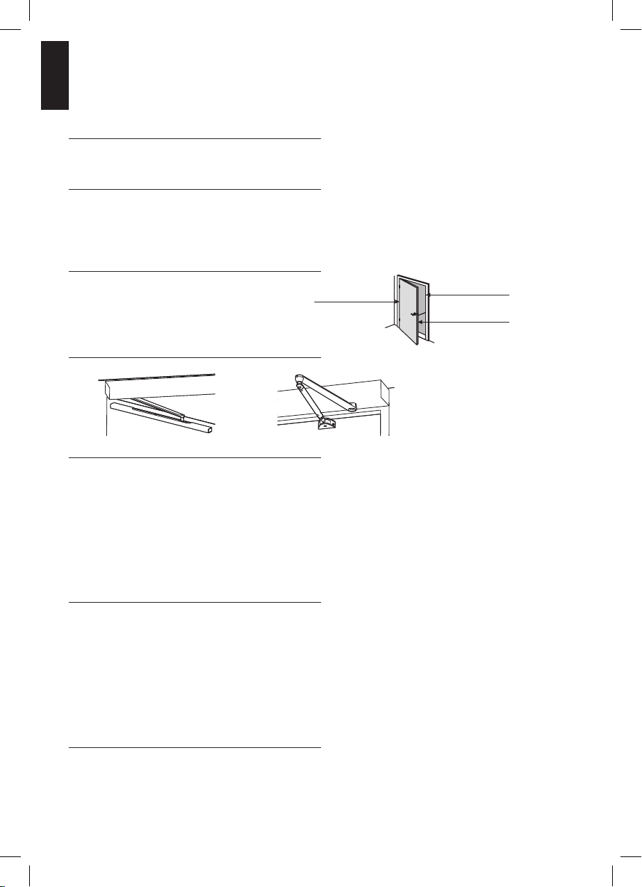
• Before installing the PORTEO the door leaf has to be checked with respect to proper mechanical
condition and smooth running.
• The mounting of the PORTEO described herein is only an example. Structural or local conditions,
available tools or other conditions might suggest a different approach.
• Following the successful installation of the system, the settings and the proper function of the
PORTEO and the safety equipment have to be checked.
• Only specially qualified staff may open the power supply housing.
• Disconnect the PORTEO from power supply (de-energise the system) before removing the cover of
the power supply housing. Remove mains plug or switch off fuse (with permanent power supply).
• Always pull at the plug and never at the cable when unplugging the power supply.
Safety during commissioning
• The protective earth conductor has to be connected.
• The safety sensors are to be connected (see commissioning instructions).
• Separately supplied components such as the program switch, the EMERGENCY OFF pushbutton
and activators (radar motion detectors, NIGHT-/BANK key switches) have to be mounted and
connected.
• Ensure that the door leaves run smoothly
• The operator and the door leaf must be properly linked.
Inspection and system approval
Before the first commissioning and depending on requirements, however, at least once a year, the
PORTEO has to be inspected by a properly qualified technician and serviced if required.
A person trained by DORMA has to perform the inspection and approve the system with the aid of
the inspection book.
The respective results have to be documented in accordance with DIN 18650-2 and other local laws
and standards and the facility operator has to keep these documents for at least one year.

PORTEO
—
GB 9DORMA
Subheadline 1
Subheadline 2
We would recommend taking out a maintenance agreement with DORMA.
Briefing
Following the adjustment, commissioning and functional testing of the door system, the operating
instructions have to be handed over to the facility operator and a briefing has to be made.
Maintenance
The system has to be de-energised (disconnected from power supply) before performing any kind
of maintenance work. Remove the power plug or switch off the fuse (with permanent power
supply).
We would recommend taking out a maintenance agreement with DORMA.
Care
The system has to be de-energised (disconnected from power supply) before cleaning the system.
Remove the power plug or switch off the fuse (with permanent power supply).
You may clean the PORTEO with a damp cloth and standard commercial detergents.
You should not use scouring agents for cleaning purposes as they might damage the surface
finish.
Ensure that no water or other liquids drop on or into the PORTEO
Never stick metal objects into the openings of the PORTEO doing so may result in electric shock.
Wear
The slide piece has to be inspected at regular intervals (every year) and replaced if required.
Only use original spare parts.
PORTEO -certified safety
geprüfte
Sicherheit
Developed according to the latest safety standards:
+ “low energy” according to DIN 18650
+
geprüfte
Sicherheit
TÜV approval
+ mark
+
GGT-seal of approval
The TÜV certificate and the -certificate can be obtained from the manufacturer
on demand.

PORTEO
—
GB 10 DORMA
2. Standard scope of delivery
Status on delivery
The operator is supplied with a mains plug. Ready-to-plug-in incl. power cord.
A 2-pole-and-earth mains plug with 10 A fuse protection must be available. The power supply
(230V AC or 100 V AC (± 15%), 50/60 Hz, 65 VA, IP 20) has to be provided by others.
1
2
3
4
5
6
7
8
9
10
11
12
13
14
15
A
Use the enclosed
tools to adjust
the potentiometers.
Mounting plate
Drive unit
Cover
Cover
Axle cover, top
Axle cover bottom
Power cord
Cover
DORMA Logo
Slide channel arm
Fixing screw
Fixing screw
Slide channel
Cover of slide channel
Fixing material
a) Drive unit/Mounting plate
b) Slide channel
Documentation
(without illustration)
- Installation drawings
- Extended documentation
- Drilling template
- 60° angle template
- 420 mm template
Storage place for
potentiometer tool
17
7901 507901 50
1
2
3
5
4
6
8
7
9
17
9
15
14
9
13
b)
a)
1x 2x
1x 2x2x 2x
b)
a)
A
10
12 11
2x

PORTEO
—
GB 11DORMA
3. Status on delivery and assistance when it comes to selecting appropriate accessories
Required accessories for the respective way of mounting
Lintel mounting:
– on the hinge side (pull-side),
left-handed version
– on the hinge side (pull-side),
right-handed version
– on opposite hinge side (push-side),
left-handed version
– on opposite hinge side (push-side),
right-handed version
Standard
Obligatory accessories
none
Door-leaf mounting:
– on the hinge side (pull-side),
left-handed version
– on the hinge side (pull-side),
right-handed version
–
on the opposite hinge side (push-side),
left-handed version
–
on the opposite hinge side (push-side),
right-handed version
When it comes to
door-leaf mounting,
the power cord has to be
protected from crushing.
Cable loop -option
Art.-No. 60041401
Option
Lintel mounting with projecting arm.
Compulsory for lintel depths beyond
30 mm:
–
on the opposite hinge side (push-side),
left-handed version
–
on the opposite hinge side (push-side),
right-handed version
On application of the
projecting arm, the
slide channel is no longer
required.
Projecting arm
Lintel depths from
30 to 90 mm
Lintel depths from
90 to 200 mm
Please ask for our template
WN-No.: 057193-45532
Required tools for the installation of the PORTEO door assistant
– Allen key, 5 mm (Scope of delivery)
– Potentiometer-tool (Scope of delivery)
– Power drill
– Drill bit, depending on surface
Authorised DORMA specialist dealers offer competent advice and the required accessories
for the PORTEO door assistant.

PORTEO
—
GB 12 DORMA
4. “Door basics” technical terms
Rebate dimensions
Lintel depth
Lintel mounting
Door hinge
Hinge side
Main closing edge
Opposite hinge side
Example 3
• Lintel mounting on opposite hinge side (push side)
• Left-handed design (right-handed version is laterally reversed)
• PORTEO door assistant with rack & pinion arm (option)
A rack & pinion arm (option) has to be applied on the hinge side
when it comes to lintel depths of more than 30 mm.
Example 2
• Door leaf mounting on hinge side (pull side)
• Left-handed design (right-handed version is laterally reversed)
• PORTEO door assistant with slide channel (standard)
Example 1
• Lintel mounting on opposite hinge side (push side)
• Left-handed design (right-handed version is laterally reversed)
• PORTEO door assistant with slide channel (standard)
A rack & pinion arm has to be applied on the hinge side when it
comes to lintel depths of more than 30 mm.

PORTEO
—
GB 13DORMA
5. Function and adjustments
General information
The PORTEO door assistant has been pre-adjusted for various kinds of applications (basic settings).
The settings: swing direction, door weight, door width, way of mounting, “closed” and “open”
position are important for the smooth and proper operation of the door system.
Some of these settings are part of the basic settings, others have to be determined while some
settings are determined automatically during the learning cycle.
The determination of the settings is a simple and plain procedure that is described on the
pages 16 to 21.
Function
The opening or closing cycle is triggered either by active or automatic activators.
The activator sends a signal to the control unit.
The control unit in turn sends the pulse to the motor.
The motor starts and converts the pulse into a movement.
The arm transfers the movement of the motor onto the door.
The door performs either an opening or a closing cycle.
There are either active or automatic activators.
Active activators are for example pushbuttons or door handles while automatic activators are radar
motion detectors or sensors.
Settings / Adjustments
The control unit of the PORTEO door assistant requires the following parameter settings for
control-internal operations:
• swing direction -left or right
• way of mounting -lintel mounting or door leaf mounting
• mounting side -hinge side/pull side or opposite hinge side/push side
• lintel depth (see page 12)
• type of accessory -slide channel (standard) or projecting arm
• door width
• door weight
• position of the door when closed (“closed” position)
• position of the door when it is completely open (“open” position, freely adjustable)
• and latching action.
Each setting is learnt automatically during commissioning.
Follow the instructions indicated in the commissioning instructions:
• Standard commissioning see pagen 16 and 17
• Extended commissioning see pagen 18 to 21

PORTEO
—
GB 14 DORMA
6. Approach to installation and commissioning
1. Determine the power connection, either:
Plug&Go (power connection via power plug)
or
Power supply straight through the wall, see page 28 for details.
This connection version may only
be performed by a properly qualified
company.
230 / 100 VAC
2. Perform the mounting with the aid of the enclosed installation
drawings.
Select the appropriate installation drawing for your way of mounting.
Lintel mounting with slide channel (standard).
ABCD
Door leaf mounting with slide channel
EFGH
Lintel depth mounting. with projecting arm (option).
Please ask for the template
WN-No.: 057193-45532
IJ
3. Following the installation, commission the PORTEO door assistant.
Either with standard commissioning,
see operating instructions on page 16 and 17
or
with extended commissioning,
see operating instructions on page 18 to 21.
Betriebsanleitung

PORTEO
—
GB 15DORMA
7. Requirements for standard commissioning
Basic settings
The basic settings offer base values for these settings:
max. 1.000 mm
max.
60
kg
- lintel mounting
- with slide channel
- on the hinge side (pull side)
- door weight of up to 60 kg
- door width of up to 1,000 mm
Most interior doors have a door width of less than 1,000 mm and a door weight of less than
60 kg. As far as the structural conditions as well as the basic values of the lintel-mounted
operator with slide channel on the hinge side (pull side) correspond to the above-mentioned
basic values, the door closer can be commissioned with the aid of the standard commissioning.
Deviations from basic values of original settings
In case the basic values are not identical with the basic values of the original settings, the deviant
settings have to be determined and adjusted during the extended commissioning.
page 18 to page 21
Door leaf width and admissible maximum weights
door leaf width in mm max. door weights in kg
600 140
700 130
800 120
900 110
1,000 100
1,100 100
In case the basic values are not identical with the basic settings,
the deviant settings have to be determined and adjusted.
The deviant settings are determined and readjusted during the
“extended commissioning”.

PORTEO
—
GB 16 DORMA
8. Standard commissioning
1
Standard commisioning
Requirements
• The PORTEO door assistant has been installed.
• The door can easily be moved by hand.
• Perform the following steps of the standard commissioning one after the other.
• The (visual) acknowledgement is made via the light indicator (LED).
• You can stop and restart this procedure at any time by simply switching off the system.
The stored settings can be “overwritten” by a new commissioning procedure.
The “approach” describes the commissioning of the standard system.
Accessories like for example electric strikes or sensors are adjusted following the successful
commissioning of the system.
Set power switch to “0FF”
– Set program switch to “0” position
(central position).
Close door
– Connect power plug.(2 x 0,75)
2
0
0
I
II
0FF
ON
0N
0
FF

PORTEO
—
GB 17DORMA
Subheadline 1
Subheadline 2
3
4
Determination of swing direction:
– Open door by approximately 5°.
Determination of swing direction:
Simultaneously, until the door starts moving,
– Press service key and switch on power
switch. Press and hold service key
for 8 sec. until the door starts moving,
then release the service key.
The LED (green) blinks.
The door determines the swing direction and
travels to its “closed” position.
5 Determination of “open” position:
– Move door to desired “open” position.
The LED (green) blinks.
– Press service key once
The LED emits a permanent light for 3 sec.,
then it blinks
The door determines this position as its “open”
position. The door travels to its “closed”
position.
The LED (green) emits permanent light.
Following the learning cycle, the PORTEO door assistant is ready for operation.
Now you can perform further adjustments like speed, hold-open time or adjustments regarding
the optional accessories like for example the electric strike, see adjustments page 24 and 25.
6
~5°
Service pushbutton
LED (green)
0FF
0N
max. 110°

PORTEO
—
GB 18 DORMA
9. Extended commissioning
Preparation 1
When it comes to deviations from the basic values of the original settings (see page 15),
an extended commissioning is required.
For example:
• projecting arm instead of slide channel
• a different door width (more than 1,000 mm
• a different door weight more than 60 kg)
Approach in case of extended commissioning and learning cycle
You can stop and restart this procedure at any time by simply switching off the system.
Requirements:
• The PORTEO door assistant has been installed.
• The door can easily be moved by hand.
The stored settings can be “overwritten” by a new commissioning procedure.
The “approach” describes the commissioning of the PORTEO door assistant without any accessory.
Accessories like for example electric strikes or sensors are adjusted following the successful
commissioning of the system.
Select an arm version:
Set DIP switch to “A” position
– “ON” = projecting arm
– “OFF” = slide channel
(Set the switch to the correct position with the
aid of a small screwdriver.)
Following commissioning
the DIP switch “A” has a different function,
see page 25
“latching action”
Always set DIP switches “B”, “C” and “D” to
“OFF” position
Close the door.
ON
1234
ABCD
OFF
1234
ABCD
ON
OFF
ON
1234
ABCD
OFF
1234
ABCD
ON
OFF
ON
1234
ABCD
OFF
1234
ABCD
ON
OFF
Preparation 2
Extended commissioning

PORTEO
—
GB 19DORMA
Subheadline 1
Subheadline 2
1
2
Connect power plug. (2 x 0,75)
Set power switch to “ON” position.
– Set program switch to “OFF” position
(central position).
The LED (green) blinks.
3 Determination of swing direction:
– Open door by approximately 5°.
The LED (green) blinks.
0
~5°
0FF
ON
0
I
II
0FF
0N
Service pushbutton
LED (green)
0
~5°
0FF
ON
0
I
II
0FF
0N
Service pushbutton
LED (green)
0
~5°
0FF
ON
0
I
II
0FF
0N
Service-Taster
LED (grün)

PORTEO
—
GB 20 DORMA
9. Extended commissioning
4
5
Determination of swing direction:
– Press service key, until the door starts
moving (approx. 3 sec.).
The LED (green) emits a permanent light
for 3 sec., then it blinks
During this procedure the control unit
determines and stores the swing direction of
the door.
The door travels to “closed” position.
Teaching-in the way of mounting and arm
version:
– Open door by approximately 60°.
(60° angle template is enclosed).
The LED (green) blinks.
– Press service key once.
The LED (green) emits a permanent light
for 3 sec., then it blinks
During this procedure the control unit
determines and stores the way of mounting
and the arm version.
6 Teaching-in the door width:
– Open the door by approximately 420 mm
(420 mm angle template is enclosed).
The LED (green) blinks.
– Press service key once.
The LED (green) emits a permanent light
for 3 sec., then it blinks
During this procedure the control unit
determines and stores the door width.
LED (green)
Service pushbutton
420mm
60°
Service pushbutton
Service pushbutton
LED (green)
LED (green)
LED (green)
Service pushbutton
420mm
60°
Service pushbutton
Service pushbutton
LED (green)
LED (green)
LED (green)
Service pushbutton
420mm
60°
Service pushbutton
Service pushbutton
LED (green)
LED (green)
Other manuals for PORTEO
2
Table of contents
Other Dorma Door Opening System manuals

Dorma
Dorma G-EMF Series User manual

Dorma
Dorma EMR Series User manual

Dorma
Dorma ES 68 User manual

Dorma
Dorma 8916 TDE User manual

Dorma
Dorma 9800 Series User manual

Dorma
Dorma PORTEO Guide

Dorma
Dorma AGILE 150 User manual

Dorma
Dorma GK 20 User manual

Dorma
Dorma 8616 PH User manual

Dorma
Dorma TS93-5 PKT 90 User manual
Popular Door Opening System manuals by other brands

Erreka
Erreka RINO-I Quick installation and programming guide

schmersal
schmersal AZ 01 operating instructions

Yale
Yale YDC201 installation instructions

Synergy
Synergy S800 Series Fixing instructions

Assa Abloy
Assa Abloy Corbin Russwin DC3200 Series installation instructions

Chamberlain
Chamberlain Liftmaster MT5011 owner's manual