manuals.online logo
Brands
  1. Home
  2. •
  3. Brands
  4. •
  5. Dorma
  6. •
  7. Door Opening System
  8. •
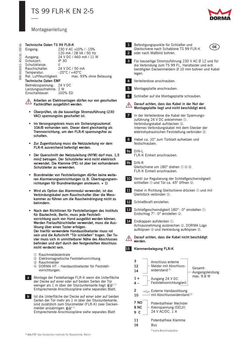
  9. Dorma CS 80 MAGNEO User manual

Dorma CS 80 MAGNEO User manual

Auf-Wand Montage On-wall mounting
CS 80 MAGNEO
WN 058347 45532, 11/12
Türenkit Glasklemmschiene / Door kit glass clamping rail
Für eine vollständige Türinstallation benötigen Sie:
• Verkleidungs-/ Befestigungskit für Glasklemmschiene
• Türenkit Glasklemmschiene
• Glastürflügel
• CS 80 MAGNEO Antrieb
Montagewinkel
mounting bracket
Ausgleichsbleche
shim plates
Befestigungswinkel In-Wand Montage
Bracket for in-wall mounting
Futterplatte (Zubehör)
shim plate (option)
Bodenführung In-Wand Montage
Floor guide rail for in-wall mounting
Glasklemmschiene
glass clamping rail
Antrieb nicht im Lieferumfang enthalten.
operator not part of the scope of delivery
Verkleidung
cover
Türflügel nicht im Lieferumfang enthalten
Door panel not part of the scope of
delivery.
floor guide
Bodenführung
Inhaltsverzeichnis contents
D Arbeitsvorbereitung und Hinweise 2 - 5
Montage 6 - 10
GB Required preparation and instructions 2 - 5
Mounting 6 - 10
To build a complete door system you need:
• operator
• Cover kit/fixing kit for glass clamping rail
• Door kit glass clamping rail
• Glas door panel
CS 80 MAGNEO
Die DORMA MAGNEO Schiebetürautomatik ist ein
Baukastensystem.
Das vorliegende ist eine Komponente des
Baukastensystems DORMA MAGNEO
Schiebetürautomatic.
Für eine vollständige Türinstallation benötigen Sie
zusätzlich zu diesem noch folgende
Kompontenen: Türflügel (Extern), das Verkleidungs- und
Befestigungskit, den Antrieb und soweit gewünscht das
zusätzliche Zubehör.
CS 80
Türenkit
CS 80
Türenkit
The sliding door is a modular
system.
The present door kit is one component of the modular
system s .
DORMA MAGNEO
DORMA MAGNEO
CS 80
CS 80 liding door
or a complete door installation you will need the following
components in addition to this kit:door leaf (external),
cover- and fixing kit, the drive unit and as far as desired
additional accessories.
F
Auf-Wand Montage On-wall mounting
CS 80 MAGNEO
WN 058347 45532, 11/12
Türenkit Glasklemmschiene / Door kit glass clamping rail
Before you start ...
Work on electrical equipment may only be performed
by properly qualified staff (electricians).
For installations with permanent power supply (where
the mains supply comes directly out of the wall), the
system has to be disconnected from power supply
before you start mounting.
The mains cable, max. 3 x 1.5 mm (earthed outlet
socket or permanent power supply), must be equipped
with a 10 A fuse protection.
Opening direction:
1. Safety instructions
1.1 Specified standard operation
1.2 Product-specific characteristics
1.3 Standards, laws, codes and regulations
Residual risks
·
·
·
·
The floor has to be even.
Always use safety glass when installing glass door
panels.
Connection lines (program switch etc.) have to be
provided within the close range of the operator before
you start mounting the system. Please ensure that the
drill holes for the cables are sufficiently big and do not
have sharp edges.
With in-wall mounting, the wall must not be closed
before the mounting has been completed.
The operator has to be installed so that the
connections are always located on the side where the
door is when in "closed” position.
The operator is of symmetrical design and can be
installed laterally reversed, if desired.
In these mounting instructions, the connection is
located on the right side.
If you would like to realise the connections on the left
side, simply install the system laterally reversed.
The is only designed to open and
close small and light interior doors with an admissible
weight from 20 kg to 80 kg per door panel.
Do not allow children to play with the
or rigidly mounted adjustment and/or control devices.
Keep remote controls out of reach of children.
A door kit is provided to make the connection with the
door leaf.
The is designed for application on
single-panel interior doors.
Automatic doors might cause hazards by crushing,
shearing, hitting and drawing-in. Depending on the
structural conditions, the door version and the safety
equipment, residual risks cannot be excluded.
2
CS 80 MAGNEO
CS 80 MAGNEO
CS 80 MAGNEO
Bevor Sie beginnen ...
Arbeiten an Elektroanlagen dürfen nur von
geschulten Fachkräften (Elektriker)
ausgeführt werden.
Bei der Montage mit Festanschluss (das Kabel kommt
direkt aus der Wand) muss der Netzanschluss vor der
Montage spannungsfrei geschaltet werden.
Die Zuleitung, max. 3 x 1,5 mm
(Schutzkontaktsteckdose oder Festanschluss),
muss mit 10 A abgesichert sein.
Öffnungsrichtung:
1. Sicherheitshinweise
1.1 Bestimmungsgemäßer Gebrauch
CS 80 MAGNEO
1.2 Produktspezifische Eigenarten
1.3 Normen, Gesetze, Richtlinien und Vorschriften
Restrisiken
·
·
·
·
Der Boden muss eben sein.
Bei Türflügeln aus Glas muss Sicherheitsglas
verwendet werden.
Die Anschlussleitungen für externe Geräte
(Programmschalter etc.) müssen vor Beginn
der Montage in unmittelbarer Nähe des Antriebs
verlegt sein. Die Durchgangsbohrungen für die
Leitungen müssen großzügig ausgelegt und dürfen
nicht scharfkantig sein.
Bei Montage in der Wand darf die Wand nicht vor der
Montage geschlossen werden.
Die Anschlussseite des Antriebs ist immer die
"Tür-ZU-Position".
Der Antrieb ist symmetrisch aufgebaut und kann je
nach Wunsch umgedreht werden.
In dieser Montageanleitung wird der Anschluss auf der
rechten Seite gezeigt.
Die Montage mit Anschluss auf der linken Seite erfolgt
entsprechend spiegelbildlich.
Der Antrieb dient ausschließlich dem
Öffnen und Schließen von einflügeligen Schiebetüren
im Innenbereich mit einem zulässigen
Türflügelgewicht von 20 bis 80 kg.
Kinder nicht mit dem oder fest
montierten Regel- und Steuereinrichtungen spielen
lassen. Fernsteuerungen außerhalb der Reichweite von
Kindern halten.
Die Anbindung an den Türflügel erfolgt über einen
Türenkit.
Der ist nicht zur Verwendung in
Rettungswegen, an Brandschutztüren (Feuer-
/Rauchschutztüren) und im Außenbereich geeignet.
An automatischen Türen können Quetsch-, Scher-,
Stoß- und Einzugsgefahren entstehen. Je nach
baulicher Gegebenheit, Türvariante und
Absicherungsmöglichkeit können Restgefahren nicht
ausgeschlossen werden.
2
CS 80 MAGNEO
CS 80 MAGNEO
Auf-Wand Montage On-wall mounting
CS 80 MAGNEO
WN 058347 45532, 11/12
Türenkit Glasklemmschiene / Door kit glass clamping rail
Haupt-
schließkante
Neben-
schließkante
Main
closing edge
Secondary
closing edge
CS 80 MAGNEO Antrieb als Niedrigenergieprodukt gemäß
deutscher DIN 18650
Reduzierte Fahrgeschwindigkeiten (reduzierte
dynamische Türflügel-/Berührkräfte)
Kraftbegrenzung (reduzierte statische Türflügel-
/Berührkräfte)
Gefahrenstellen an Schließkanten
Laut deutscher Norm DIN 18650 ist der Fahrbereich
einer automatischen Tür grundsätzlich u.a. durch den
Einsatz von Sicherheitssensoren abzusichern.
Bei Einsatz eines Niedrigenergieproduktes gelten
jedoch spezielle Anforderungen.
Der Antrieb erfüllt durch die
Einhaltung folgender Vorgaben die Anforderungen
eines Niedrigenergieantriebes im Sinne der Norm:
An automatischen Türen können an den verschiedenen
Schließkanten Quetsch-, Scher-, Stoß- und
Einzugsgefahren entstehen.
CS 80 MAGNEO
·
·
CS 80 MAGNEO as low-energy product according to
German DIN 18650 (German Industrial Standard)
Reduced driving speeds (reduced dynamic force at
door panel/contact force)
Force limitation (reduced static force at door
panel/contact force)
Danger spots at closing edges
According to the German Industrial Standard DIN
18650, the movement range of an automatic door
always has to be protected (amongst others) by safety
sensors.
However, there are special requirements for low-energy
systems.
The meets the requirements of a low-
energy operator according to the standard by fulfilling
the following requirements:
Automatic doors might cause hazards by crushing,
shearing, hitting and drawing-in at the different
closing edges.
CS 80 MAGNEO
·
·
Absicherungserfordernisse gemäß DIN 18650 für den
Absicherungserfordernisse gemäß DIN 18650 im
Voll Energie Modus.
Risikobewertung durch Einbauer
CS 80 MAGNEO
CS 80 MAGNEO
In der deutschen Norm DIN 18650 finden sich
verschiedene Vorgaben für die Absicherung der
vorgenannten Gefahrenstellen.
Für den Einsatz des Antrieb gilt:
Die zusätzliche Absicherung der Türanlage ist nicht
zwingend vorgeschrieben.
Der Einsatz von Sicherheitssensoren an den
Schließkanten als zusätzliche Absicherung ist optional
und liegt als Ergebnis einer individuellen
Risikobewertung im Ermessen der den Einbau
vornehmenden Person
Insgesamt: Hoher Sicherheitsstand in der Anwendung!
In diesem Modus sind die Kräfte ebenfalls begrenzt.
Eine Sicherheitsausrüstung ist wegen der höheren
Berührkräfte vorgeschrieben. Die
Sicherheitsausrüstung muss von einem Fachmann
unter Berücksichtigung der DIN 18650 eingebaut
werden.
Aufgrund besonderer räumlicher Gegebenheiten und
der zu erwartenden Nutzergruppen der Tür kann der
Einsatz von Sicherheitssensoren auch im
Niedrigenergiebetrieb für sinnvoll erachtet werden.
Diese müssen von einem Fachmann unter
Berücksichtigung der DIN 18650 eingebaut werden.
Dies ist bei der Planung und vom Hersteller, d.h. der
den Einbau vornehmenden Person, im Rahmen einer
individuellen Risikobewertung zu beurteilen.
·
·
·
Required protection equipment for
according to DIN 18650
Safety requirements according to DIN 18650 in the
Full Energy mode
Risk assessment on the part of the installer
CS 80 MAGNEO
CS 80 MAGNEO
The German Industrial Standard DIN 18650 stipulates
different requirements regarding the protection of the
above-mentioned danger spots.
Systems with offer the following
benefits:
The door systemdoes not have to be equipped with
additional protection equipment (not compulsory).
The application of safety sensors at the closing edges
as additional protection is optional and lies in the
discretion of the person performing the installation of
the door system - under consideration of the result of
the individual risk assessment.
All the system offers a high safety standard!
The actuating forces are also limited in this mode.
However, due to the higher contact forces that can
occur, a safety kit must be installed. This must be
done by a specialist in accordance with DIN 18650 or
equivalent national safety regulations.
Special spatial conditions and certain user groups
might make it sensible to equip the application with
safety sensors – even when the system is operated in
Low-Energy-Mode. These sensors have to be installed
by a properly qualified person in accordance with
DIN 18650.
Whether this is required or not has to be assessed with
the aid of an individual risk assessment and must be
considered during the planning of the system and by
the manufacturer, i.e. the party performing the
installation of the system.
·
·
·
Auf-Wand Montage On-wall mounting
CS 80 MAGNEO
WN 058347 45532, 11/12
Türenkit Glasklemmschiene / Door kit glass clamping rail
Wir verweisen hierzu auf das zur Unterstützung der
Durchführung zur Verfügung stehende
Formular Risikobewertung. Sie erhalten es über unsere
Homepage
Soweit die Risikobewertung die Gefahr eines im
Hinblick auf ein Gesundheits- oder Verletzungsrisiko
inakzeptablen Anstoßes eines Türnutzers ergibt, muss
eine Absicherung durch eine Schutzeinrichtung
(Anschluss von Sicherheitssensoren) ergänzend
erfolgen. Dies gilt insbesondere dann, wenn im
Türbereich mit besonders schutzbedürftigen Personen
(Kinder, ältere Personen oder Behinderte) gerechnet
werden muss.
Der darf nur gemäß seiner
bestimmungsgemäßen Verwendung eingesetzt werden.
Eigenmächtige Änderungen am
schließen jede Haftung durch die
für daraus resultierende
Schäden aus.
Die Unterlagen sind aufzubewahren.
Sichern Sie den Arbeitsplatz gegen unbefugtes
Betreten.
Herabfallende Teile oder Werkzeuge können zu
Verletzungen führen.
Befestigungsart und -mittel, wie z. B. Schrauben und
Dübel, müssen auf jeden Fall den baulichen
Gegebenheiten angepasst werden (Beton, Holz,
Gipskarton etc.).
Wenn der Endanschlag losgeschraubt ist, kann er
mitsamt des Laufwagens herausfallen. Deshalb den
Antrieb immer gerade halten.
Lassen Sie kein Wasser oder andere Flüssigkeiten auf
oder in den gelangen.
Laufwagen enthält starke Permanentmagnete und darf
nicht ausgebaut werden.
Führen Sie niemals Metallgegenstände in die
Öffnungen am ein. Andernfalls
besteht die Gefahr eines elektrischen Schlages.
Greifen Sie niemals in den , so
vermeiden Sie Verletzungen.
www.dorma-magneo.de
Besonderes Absicherungserfordernis hinsichtlich
schutzbedürftiger Personen
1.4 Haftungsbeschränkung
DORMA GmbH + Co. KG
1.5 Montage und Gebrauchsanweisung des Antriebs
Die Verwendung von Steuerelementen, Einstellungen
oder Verfahren, die hier nicht beschrieben sind,
können elektrische Schläge, Gefahren durch
elektrische Spannungen/Ströme und/oder Gefahren
durch mechanische Vorgänge verursachen.
Für Ihre Sicherheit ist es wichtig, allen enthaltenen
Anweisungen Folge zu leisten.
Eine falsche Montage kann zu schwerwiegenden
Verletzungen führen.
1.6 Allgemeine Hinweise zur Montage-, Wartungs- oder
Reinigungsarbeiten
Bei Montage-, Wartungs- oder Reinigungsarbeiten
muss der Antrieb spannungsfrei sein.
Netzstecker ziehen oder bei Festanschluss Sicherung
ausschalten.
CS 80 MAGNEO
CS 80 MAGNEO
CS 80 MAGNEO
CS 80 MAGNEO
CS 80 MAGNEO
CS 80 MAGNEO
·
·
·
·
·
·
·
We would therefore ask you to have a look at our “risk
assessment form”, which is available on our homepage
and will help you to perform
the risk assessment.
In case the risk assessment reveals that there is a
health risk or risk of injury when the door hits a user in
an unacceptable way, additional protection via safety
equipment (connection of safety sensors) is required.
This is especially necessary when people in need of
protection (children, elderly people or disabled people)
use the door.
These safety devices must be installed by a specialist
in accordance with DIN 18650 or equivalent national
safety regulations.
The may only be used according to its
specified intended application.
will not accept any liability
for damage resulting from unauthorised modifications
of the system.
Please keep this documentation for later reference.
Secure the working area against unauthorized access
of other people.
Falling items or tools might cause injuries.
In any case, the way of mounting and the mounting
equipment, like for example screws and wall plugs,
have to be adequate with regard to the structural
conditions (concrete, wood, plasterboard etc.).
As soon as you have relaxed the screws of the end
stop, both the end stop and the carrier could fall out
of the operator. Therefore you should always hold the
operator straight.
Pay attention that no water or other liquids drop on or
into the .
The carrier contains strong permanent magnets and
must not be removed.
Never stick metal objects inside the openings of the
.
Otherwise you could sustain an electric shock.
Never put you hand inside the in
order to avoid injuries.
www.dorma-magneo.com
Special requirements regarding the protection of people in
need of protection
1.4 Limitation of liability
1.5 Documentation
Using control elements, making adjustments or
performing procedures that are not described herein
might cause electric shocks, danger caused by electric
voltage/current and/or dangers due to mechanical
incidents.
1.6 General information regarding the installation of the
system
The must be disconnected from
power supply (de-energized) when performing
mounting or installation work. Remove the power plug,
or, in case of permanent power supply, switch off fuse.
CS 80 MAGNEO
DORMA GmbH + Co. KG
It is important for your personal safety to abide by the
instructions mentioned in this documentation. An
incorrectly performed installation of the system might
cause serious injuries.
CS 80 MAGNEO
CS 80 MAGNEO
CS 80 MAGNEO
CS 80 MAGNEO
·
·
·
·
·
·
·
Auf-Wand Montage On-wall mounting
CS 80 MAGNEO
WN 058347 45532, 11/12
Türenkit Glasklemmschiene / Door kit glass clamping rail
CS 80 MAGNEO – ausgezeichnete Sicherheit:
Entwickelt nach den neuesten Sicherheitsstandards:
Niedrigenergiebetrieb gemäß DIN
-Geprüfte Sicherheit
-Kennzeichnung
Das TÜV-Zertifikat und die -Erklärung
können beim Hersteller angefordert werden.
CS 80 MAGNEO Awarded safety–
Developed according to the latest safety standards:
Low-Energy-Mode in
accordance with DIN standard
Tested Safety
- mark
The TÜV certificate and the certificate can be
obtained from the manufacturer on demand.
·
·
·
·
·
·
·
Nur qualifizierte Fachleute dürfen das
Netzanschlussgehäuse öffnen.
Verlegen Sie das Netzkabel so, dass niemand darüber
stolpern oder es versehentlich herausreißen
kann.Verwenden Sie den nicht, wenn
das Netzkabel beschädigt ist.
Fassen Sie das Netzkabel nur am Stecker und niemals
am Kabel an, um es aus der Steckdose zu ziehen.
Den Netzschalter im Antriebsprofil nur bei
stillstehender oder dauerhaft geöffneter Tür betätigen.
Im Bereich des Fahrweges der Tür dürfen an der Wand
keine Schalter, Bilder etc. angebracht sein. Fußleisten
sind bei Bedarf zu entfernen.
Im Anschluss an die Montage sind die Einstellungen
und die Funktionsweise des
und der Schutzeinrichtungen zu
überprüfen.
Die hier beschriebene Montage ist ein Beispiel.
Bauliche oder örtliche Gegebenheiten, vorhandene
Hilfsmittel oder andere Umstände können eine andere
Vorgehensweise sinnvoll machen.
CS 80 MAGNEO
CS 80 MAGNEO
·
·
Do not operate the when the power
cord is damaged.
Always pull at the plug and never at the cable when
unplugging the power supply.
Only operate the mains switch at the header profile
while the door stands still or is permanently open.
No pushbuttons/switches, pictures etc. must be
located within the door's movement range. Baseboards
have to be removed if required.
Following the successful installation of the system,
you have to check the settings as well as the
and the safety devices for proper
functioning.
The installation described herein is only an example.
Structural or local conditions, available tools or other
conditions might suggest a different approach.
This device must not be disposed of as domestic
waste.
CS 80 MAGNEO
CS 80 MAGNEO
·
·
·
·
·

Auf-Wand Montage On-wall mounting
CS 80 MAGNEO
WN 058347 45532, 11/12
Türenkit Glasklemmschiene / Door kit glass clamping rail
Futterplatte (Zubehör)*
Mounting plate (Option)*
Montagewinkel an Wand befestigen. Gleichen Sie eventuelle
Unebenheiten der Wand mit Ausgleichblechen aus.
Montagewinkel darf sich bei der Montage nicht verbiegen!
Stellen Sie sicher, dass der Montagewinkel absolut
waagerecht montiert ist und bis zu 240 kg hält.
Fix mounting bracket on wall. Use shim plates to compensate
possible unevennesses of the wall.
The mounting bracket must not deform during mounting!
Ensure that the mounting bracket is fixed at an absolutely
horizontal angle and can carry up to 240 kg.
2
1.
6x
2.
3
Öffnung Türflügelanbindung nach vorne drehen.
The open side of the door-panel connection must point to the front.
4
1.Drei Filzstücke wandseitig auf Montagewinkel kleben.
2.Antrieb an Montagewinkel mit Sicherheitsschrauben fest-
schrauben, Drehmoment 8 Nm. (Um an alle sechs Löcher
zu gelangen, muss der Laufwagen verschoben werden.)
1.Adhere three pieces of felt onto the mounting bracket (on the
inside of the part where it is connected to the wall - see picture).
2.Use safety screws to fix the operator onto the mounting bracket
(8 Nm). (You have to move the carrier in order to reach all six holes.)
centerline of passage
Durchgangsmittellinie
X = Glasscheibenhöhe + 84 mm
L = Antriebslänge
X = height of glass pane + 84 mm
L = Operator length
Mark mounting dimensions.
Montagemaße anzeichnen.
max. 8
min. 5
X
Glasscheibenhöhe
height of glass pane
6 - 8 mm
60 mm
60 mm
min. 250 mm
X
L/4
50 mm
12.
10.
L1
N
9.
8.
7.
11.
5.
4.
6.
1.
2.
L1
N
35 mm
6 mm
6 mm
150 mm
Bei Festverdrahtung
1. Endanschlag lösen.
2. Endanschlag zur Mitte des Antriebs schieben und
Schraube wieder anziehen!
3. Anschlusskabel 230 V vorbereiten: siehe Detail
4. + 5. Deckel Netzanschluss öffnen.
6. Deckel Steuerungsgehäuse vorsichtig öffnen.
7. Schrauben lösen.
8. Netzanschlusssteckdose entfernen.
9. Festanschluss anschließen.
Die Erdung muss unbedingt angeschlossen werden
10. Deckel Steuerungsgehäuse schließen.
11. + 12. Deckel Netzanschluss schließen.
13. Endanschlag auf Position 1. zurückschieben.
14. Endanschlag festschrauben (5 Nm).
Diese Arbeitsschritte dürfen nur von
geschulten Fachkräften (Elektriker)
ausgeführt werden.
nicht
For systems with permanent power supply:
1. Relax end stop.
2. Move end stop to the centre of the operator and do
not re-tighten the screw!
3. Prepare 230 V mains cable: look at detail
4. + 5. Open cover of power supply housing.
6. Open cover of control unit.
7. Relax screws.
8. Remove mains supply socket.
9. Connect system to permanent power supply.
10. Close the cover of the control unit housing.
11. + 12. Close the cover of the power supply housing.
13. Move end stop back to position 1.
14. Screw down end stop (5 Nm).
The following steps may only be performed by
properly qualified staff (electricians).
The grounding (PE) has to be connected in
any case.
3.
14.
13.
3.
3.
5
Auf-Wand Montage On-wall mounting
CS 80 MAGNEO
WN 058347 45532, 11/12
Türenkit Glasklemmschiene / Door kit glass clamping rail
GB
Bauteile zusammenstecken und Türflügelbefestigung vorbereiten.
Put parts together and prepare door-panel connection.
4 x
C
GB Glasbreite glass width
GD Glasdicke 8 - 12 mm glass thickness 8 - 12 mm
C
575
700
825
L
1.750
2.000
2.250
L
Bauteile auf Länge schneiden (bei Bedarf).
Cut parts to length (if neccessary).
Zuschnitt und Einbaumaße ermitteln.
Determine the blank and installation dimension.
Zuschnitt und Einbaumaße ermitteln.
Determine the blank and installation dimension.
5
7
6
0 Nm
0 mm
3 Nm
»135°
2.
1.
3 Nm 135° +
-10»
0 Nm
1.1.
1.1.
2.2.
3.3.
2.2.
3.3.
1.
1mm
M6 x 12 mm
Die Glasscheibe und die Glasklemmschiene
müssen im Klemmbereich sauber und fettfrei
sein.
The glass pane and the glass clamping rail
must be clean and free of grease in the
area where it is clamped in.
Glasklemmschiene an Glasscheibe befestigen.
Fix the glass clamping rail at the glass pane.
89
1.
2.
3.
3.
1. Bei geräuschetwicklung
Moosgummi einkleben.
2. Verblendung aufschieben.
3. Endkappen aufdrücken.
1. If noise emission
use stick on foam rubber.
2. Slide on cover.
3. Press on end caps.
Auf-Wand Montage On-wall mounting
CS 80 MAGNEO
WN 058347 45532, 11/12
Türenkit Glasklemmschiene / Door kit glass clamping rail
Auf-Wand Montage On-wall mounting
CS 80 MAGNEO
WN 058347 45532, 11/12
Türenkit Glasklemmschiene / Door kit glass clamping rail
max. 8 mm
11
1.
3.
2.
3.
Türflügel einhängen (1), zur Wand ausrichten (2), festschrauben (3)
Fix the door panel (1), align the door with regard to the wall (2),
and screw down (3).
Türflügel einhängen (1), zur Wand ausrichten (2), festschrauben (3)
Fix the door panel (1), align the door with regard to the wall (2),
and screw down (3).
13
Bodenführung Auf-Wand
Floor guide rail for on-wall systems
Bodenführung Auf-Wand
Floor guide rail for on-wall systems
max. 8 mm
14
3.
3.
1.
Y
4.
2.
3.
Y
1.
2.
Y
4.
Y
“Tür offen” und “Tür zu” Position einrichten. Endanschläge verschieben.
1. Tür in die gewünschte ZU bzw. OFFEN Position schieben.
2. Endanschlag lösen
3. Endanschlag an die Tür heranschieben.
Endanschläge nicht aus dem Profil nehmen!
Endanschläge dürfen nur in begrenztem Maß nach innen verschoben werden.
Bei Antriebslänge (L): 1.750 mm => Y max. 200 mm
2.000 mm => Y max. 250 mm
2.250 mm => Y max. 300 mm
4. Endanschlag festschrauben. Schrauben mit 5 Nm anziehen.
Der Endanschlag darf nicht nach außen überstehen
Adjust the door's “open“ and “closed“ position. Move the end stops.
1. First relax the end stop and move the door to the desired “open“ or “closed“ ´
position.
2. Now move the end stop along until it meets the door.
3. Do not remove the end stops from the profile!
You may only move the end stops to the inside to a limited extent.
With operator length (L): 1,750 mm => Y max. 200 mm
2,000 mm => Y max. 250 mm
2,250 mm => Y max. 300 mm
4. Then fix the end stop and tighten the screws with 5 Nm.
The end stop must not overlap.
min. 6 mm
max. 8 mm
==C
12
Türflügel in der Höhe ausrichten
Adjust the height between
the floor and the door panel
Auf-Wand Montage On-wall mounting
CS 80 MAGNEO
WN 058347 45532, 11/12
Türenkit Glasklemmschiene / Door kit glass clamping rail
3.
1.
2.
15
16
17
1.
OFF ON
ON
3.
Montieren Sie Zubehörartikel wie z. B. Funktaster oder Sensorik erst nach erfolgreicher Inbetriebnahme!
Do not mount accessories such as radio transmitters or sensors until you have successfully commissioned
the system!
2.
Änderungen vorbehalten
Subject to change without notice
Verkleidung montieren.
1. Moosgummistücke auf Antrieb kleben.
2. Wandanschlussprofile aufstecken, evt. überstehende
Profile mit Messer abschneiden.
3. Verkleidung aufstecken.
Mount the cover.
1. Adhere foam rubber pieces onto the operator.
2. Fix the wall connection profiles and remove overlapping
profiles with the aid of a knife.
3. Fix the cover.
Verkleidung vorbereiten.
1. Endkappen in die Verkleidung stecken.
Die Endkappen können je nach baulichen
Gegebenheiten an den Sollbruchstellen gekürzt
oder ausgebrochen werden.
2. DORMA Krone befestigen.
DORMA
Prepare the cover.
1. Fix the end caps inside the cover.
Depending on the structural conditions, you may
either shorten or break the end caps at the
predeterminated breaking points.
2. Fix the crown.
Inbetriebnahme
1. Kontrolle der Montage. Die Tür muss sich über den
gesamten Fahrweg leicht bewegen lassen.
2. Strom anlegen bzw. Netzstecker in die Steckdose
eingestecken.
3. Antrieb einschalten. Der CS 80 MAGNEO ist betriebsbereit.
Sollte die grüne LED blinken und der Antrieb ist ohne
Funktion, muss eine Lernfahrt durchgeführt werden. Siehe
Anleitung 058179-45532 CS 80 MAGNEO Lernfahrt.
Commissioning
1. Check the system for proper mounting. The door has to
move smoothly over the complete driving path.
2. Connect system to power supply or insert power plug into
socket.
3. Switch on operator. The is now ready for
operation.
In case the green LED blinks and the operator does not fulfil
any function, you have to perform a learning cycle. See
instructions 057452-45532 learning
cycle.
CS 80 MAGNEO
CS 80 MAGNEO
DORMA GmbH + Co. KG DORMA Platz 1 D-58256 Ennepetal Tel. +49 2333 793-0 Fax +49 2333 793-4950
www.dorma.com

Other manuals for CS 80 MAGNEO

3

Other Dorma Door Opening System manuals

Dorma TS 93 Series User manual

Dorma

Dorma TS 93 Series User manual

Dorma TS93 PT User manual

Dorma

Dorma TS93 PT User manual

Dorma G-SR BG User manual

Dorma

Dorma G-SR BG User manual

Dorma GK 20 User manual

Dorma

Dorma GK 20 User manual

Dorma G-EMF Series User manual

Dorma

Dorma G-EMF Series User manual

Dorma AGILE 150 User manual

Dorma

Dorma AGILE 150 User manual

Dorma 7300 DS User manual

Dorma

Dorma 7300 DS User manual

Dorma 8600 Series User manual

Dorma

Dorma 8600 Series User manual

Dorma TS 68 User manual

Dorma

Dorma TS 68 User manual

Dorma 8916 FT User manual

Dorma

Dorma 8916 FT User manual

Dorma 7400 DS User manual

Dorma

Dorma 7400 DS User manual

Dorma PORTEO User manual

Dorma

Dorma PORTEO User manual

Dorma 8900 Series User manual

Dorma

Dorma 8900 Series User manual

Dorma TS93 GSR/EMF User manual

Dorma

Dorma TS93 GSR/EMF User manual

Dorma MUNDUS COMFORT User manual

Dorma

Dorma MUNDUS COMFORT User manual

Dorma 8956 AF89 PD User manual

Dorma

Dorma 8956 AF89 PD User manual

Dorma PORTEO Guide

Dorma

Dorma PORTEO Guide

Dorma EMR Series User manual

Dorma

Dorma EMR Series User manual

Dorma ED 100 Installation and operation manual

Dorma

Dorma ED 100 Installation and operation manual

Dorma 7300 Series User manual

Dorma

Dorma 7300 Series User manual

Dorma 8900 FH User manual

Dorma

Dorma 8900 FH User manual

Dorma 7300 ARNP User manual

Dorma

Dorma 7300 ARNP User manual

Dorma ED 100 User manual

Dorma

Dorma ED 100 User manual

Dorma SVP-S4 DCW Series User manual

Dorma

Dorma SVP-S4 DCW Series User manual

Popular Door Opening System manuals by other brands

cinetto PS23 Assembly instructions

cinetto

cinetto PS23 Assembly instructions

Assa Abloy Norton 6300 Series Programming instructions

Assa Abloy

Assa Abloy Norton 6300 Series Programming instructions

Dormakaba 8900 FT installation instructions

Dormakaba

Dormakaba 8900 FT installation instructions

Dormakaba 8900 EMR installation instructions

Dormakaba

Dormakaba 8900 EMR installation instructions

Assa Abloy SW200 Installation and service manual

Assa Abloy

Assa Abloy SW200 Installation and service manual

Sesamo PROSWING operating instructions

Sesamo

Sesamo PROSWING operating instructions

Henderson Evolve Glass SIM Kit Fitting instructions

Henderson

Henderson Evolve Glass SIM Kit Fitting instructions

Omron D40Z instruction manual

Omron

Omron D40Z instruction manual

Assa Abloy Yale 3000 Series installation instructions

Assa Abloy

Assa Abloy Yale 3000 Series installation instructions

MAGNASPHERE HSS L2S Series installation instructions

MAGNASPHERE

MAGNASPHERE HSS L2S Series installation instructions

Dr. Hahn Turband 3 installation instructions

Dr. Hahn

Dr. Hahn Turband 3 installation instructions

Micom 2ES ALE instruction manual

Micom

Micom 2ES ALE instruction manual

Chamberlain 050DCRJWFMC manual

Chamberlain

Chamberlain 050DCRJWFMC manual

Metaflex MF5 manual

Metaflex

Metaflex MF5 manual

SIMONSWERK Anselmi AN 164 3D FVZ 12/38 manual

SIMONSWERK

SIMONSWERK Anselmi AN 164 3D FVZ 12/38 manual

Nabco Opus Control Wiring and Programming Installation Manual

Nabco

Nabco Opus Control Wiring and Programming Installation Manual

Assa Abloy Besam SP33-M manual

Assa Abloy

Assa Abloy Besam SP33-M manual

Assa Abloy Lockwood 724 Series quick start guide

Assa Abloy

Assa Abloy Lockwood 724 Series quick start guide

manuals.online logo
manuals.online logoBrands
  • About & Mission
  • Contact us
  • Privacy Policy
  • Terms and Conditions

Copyright 2025 Manuals.Online. All Rights Reserved.