Dorma EM 3000-EW AH User manual

EM 3000-EW AH
EARLY WARNING
ELECTROMAGNETIC LOCK
INSTALLATION
Version 1.8 EN / 03/2008 / www.dorma.com/fr
A. INTRODUCTION
The EM 3000-EW AH is a specialized electromagnetic lock equipped with an “Early Warning
Alarm Functions” intended for use as “A Security Door Lock” which capable of detecting early
intruders before the attempted break-in.
It can also works as a “Delay Egress Functions” intended for use as “An Emergency Delayed
Exit Door Lock”. It has a built in Exit Delay Timer using initiate device and our patented
special mechanism and hardware to operate the Local Alarm Relay and the Remote Alarm
Relay. In the normal position, the door is fail safe (power to lock), we do not need any touch
sense bar or look for a exit button to exit, just by a slight push to the door will start the exit
sequence, the push would displaced the micro-switch operating arm which is the initiate
device from it’s original position of being pressed to the open position, this is done thru the
bearing screwhead that glide the entire lock within the aluminum body cast and stretchy
screw bolt to retracts the magnetic lock back to it’s original position.
------------------------------------------------------------------------------------------------------
EM 3000-EW AH can be selected function as: :
A Security Door Lock : Dip Switch 5 is set to ON
An Emergency Delayed Exit Door Lock : Dip Switch 5 is set to OFF.
------------------------------------------------------------------------------------------------------
B. DELAY EGRESS FUNCTIONS
In the normal condition, the door is fail safe (power to lock) and locked, the local buzzer is off,
the Local Alarm Relay (SPDT, 1C) is deenergized and the Remote Alarm Relay (DPDT, 2C) is
energized.
The system will start the exit sequences by just slightly pushing the door to enter the
Nuisance Delay Period which can be set for 0, 1, 2 or 3 seconds depends on the building
codes, at the same time the Local Alarm Buzzer will sound pulsingly and the Local Alarm
Relay will be energized, warning that someone may want to exit, if that person wants to exit,
he or she must maintain pressure on the door until the end of the Nuisance Delay Period and
if he or she backs off before the time set, both the Local Alarm Buzzer and the Local Alarm
Relay will stop/be deenergized, and revert to normal operation. The purpose of Nuisance
Delay Period is to take the accidental triggering the sequence into consideration.
Once the Nuisance Delay Period time out, the Release Delay Period begins and can be set
for 15 or 30 seconds depends on the building codes, at the same time the Remote Alarm
Relay will be deenergized and the Local Alarm Buzzer will go from pulsing to steady to inform
the person at the door that he needs no longer to push the door. Please note the total
Release Delay Time also includes the Nuisance Delay Time.
Once the Release Delay Period time out, the lock is released, at the same time both the Local
Alarm Buzzer and the Local Alarm Relay will stop/be deenergized.
Once the lock is released, Reset Switch Input from OPEN to CLOSE resets the system to the

normal condition. The Remote Alarm Relay is energized when door is relocked. Please note
system can be reset only after the Release Delay Period is time out.
DELAY EGRESS SYSTEM STATUS
System
Status Light Panel Local
Buzzer Voice Local
Alarm Relay Remote
Alarm Relay
Door Open Red on OFF OFF OFF OFF
Lock
Locked
Green blinks
every 5
seconds OFF OFF OFF ON
Nuisance
Delay
Period
Red blinking
(fast) Sound
pulsingly Voice I ON ON
Release
Delay
Period
Red blinking
(slowly) Sound
steady Voice II ON OFF
Lock
Release
Red/Green
blinking
alternately OFF Voice III OFF OFF
Force to
Open Red blinking
(fast) Sound
pulsingly Voice IV ON OFF
Exit Switch
to Open Red on OFF Voice III OFF OFF
Local
Normal Condition Nuisance Delay Release Delay Door Release Reset to
(Power on & Door Locked) Period Normal Condition
Remote
Local Buzzer
Voice Message Voice Message I Voice Message II Voice Message III
Period
0 ~ 3 Seconds
15 or 30 Seconds
Alarm Relay
Alarm Relay
energized
deenergized
energized
deenergized
on
off
Delay Egress Functions
(Power on & Door Open)
Reset to
Normal Condition
(Power on & Door Locked)
Exit Switch to Open
Force to Open
Can be "Exit Switch to Open" in this period - Voice Message III
After "Exit Switch to Open" is timeout, system will be back to the normal condition
Can be "Force to Open" in this period - Voice Message IV "Force to Open"
Voice Message IV
"Exit Switch to Open"
Voice Message III

The EM 3000-EW AH supports 5 different building codes as below:
1. STANDARD BUILDING CODE
NUISANCE DELAY: Not allowed.
RELEASE DELAY: 15 sec. or ext. to 30 sec. with local approval.
RELOCKING: To be done upon door OPENS and CLOSES, using a doorswitch rather than a
keyswitch. Please connect NORMAL OPEN doorswitch to system Reset Switch Input.
2. NFPA 101
NUISANCE DELAY: Permitted up to 3 sec.
RELEASE DELAY: 15 sec. or ext. to 30 sec. with local approval.
RELOCKING: To be done manually by a keyswitch, a doorswitch cannot be used for relocking.
Please connect a momentary spring loaded NORMAL CLOSE keyswitch to system Reset
Switch Input.
3. UNIFORM BUILDING CODE
NUISANCE DELAY: Required to be set at 2 sec.
RELEASE DELAY: Required to be set at 15 sec.
RELOCKING: To be done manually by a keyswitch and must be located at the door, a
doorswitch cannot be used for relocking. Please connect a momentary spring loaded
NORMAL CLOSE keyswitch to system Reset Switch Input.
4. BOCA
NUISANCE DELAY : Required to be set at 1 sec.
RELEASE DELAY : 15 sec. or ext. to 30 sec. with local approval.
RELOCKING : Dip switch 4 must be in the OFF position to activate the relocking system after
the Release Delay expires, the door unlocks and opened, the doorswitch changes state and
remain open. When the door recloses, a relock delay of 30 sec. begins, if the door hasn’t
been disturbed or open again during this 30 sec. it will relock, if it has been open again a 30
sec. relock will start all over again. The relock time count will not start till the door is closed.
5. NATIONAL BUILDING CODE OF CANADA
NUISANCE DELAY : Not allowed.
RELEASE DELAY : Required to be set at 15 sec.
RELOCKING : To be done manually by a keyswitch, a doorswitch cannot be used for
relocking. Please connect a momentary spring loaded NORMAL CLOSE keyswitch to system
Reset Switch Input.
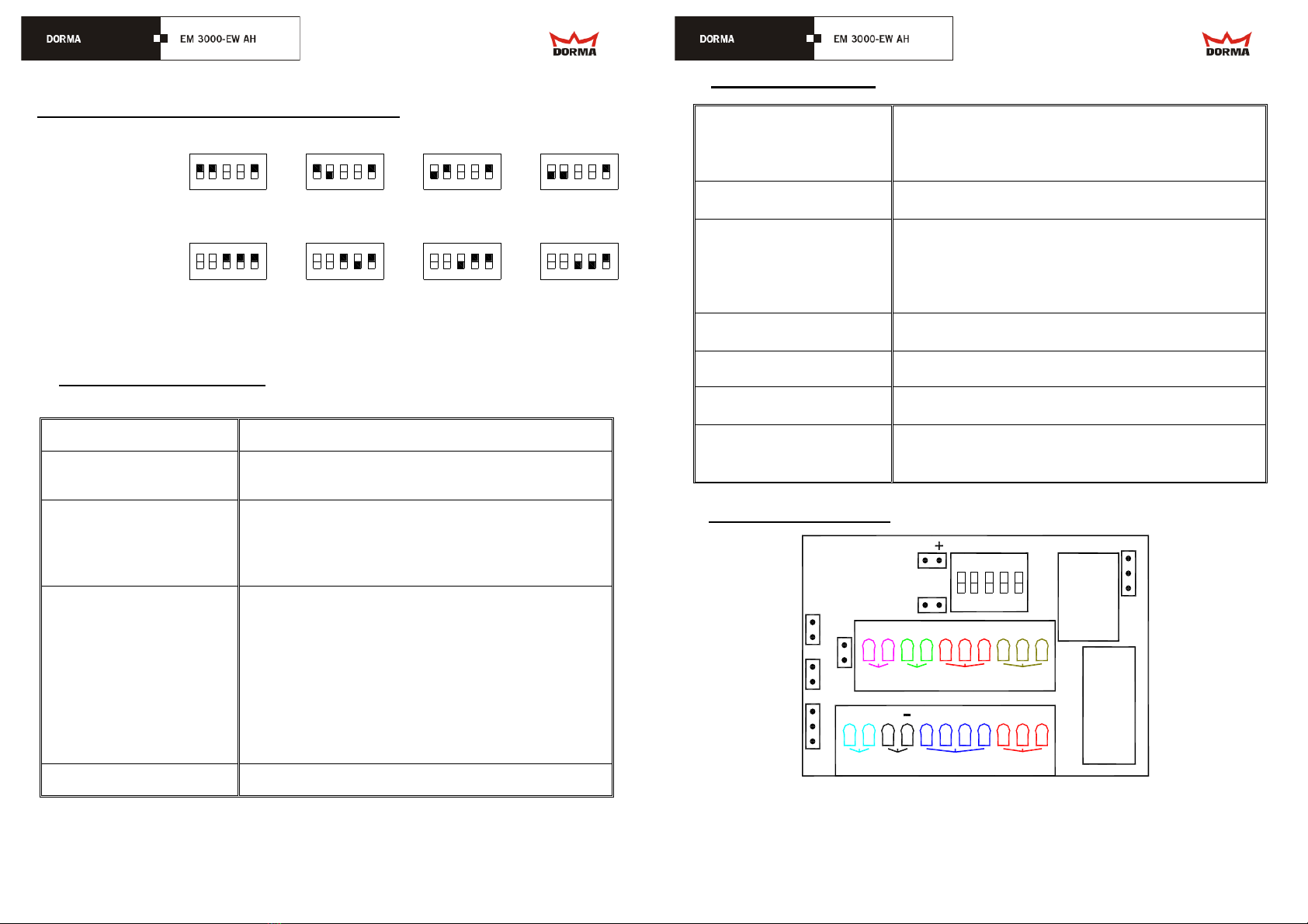
DIP SWITCH SETTING FOR DELAY EGRESS FUNCTIONS
Factory setting : Nuisance Delay set at 3 sec. (Dip switch 2 OFF and Dip switch 3 OFF).
Factory setting : Release Delay at 15 sec. (Dip switch 1 ON).
Factory setting : Not BOCA. (Dip switch 4 ON).
15 Sec.
Release Delay
Dip Switch 1
30 Sec.
1
ON
0 Sec.
Nuisance Delay
Dip Switch 2&3 234
1 Sec. 2 Sec. 3 Sec.
Non BOCA
BOCA Setting
Dip Switch 4
BOCA
5
ON ON ON
ON ON
ON ON
12 3 4 5 12 3 4 5
12345 12345
12345
12 3 4 512345
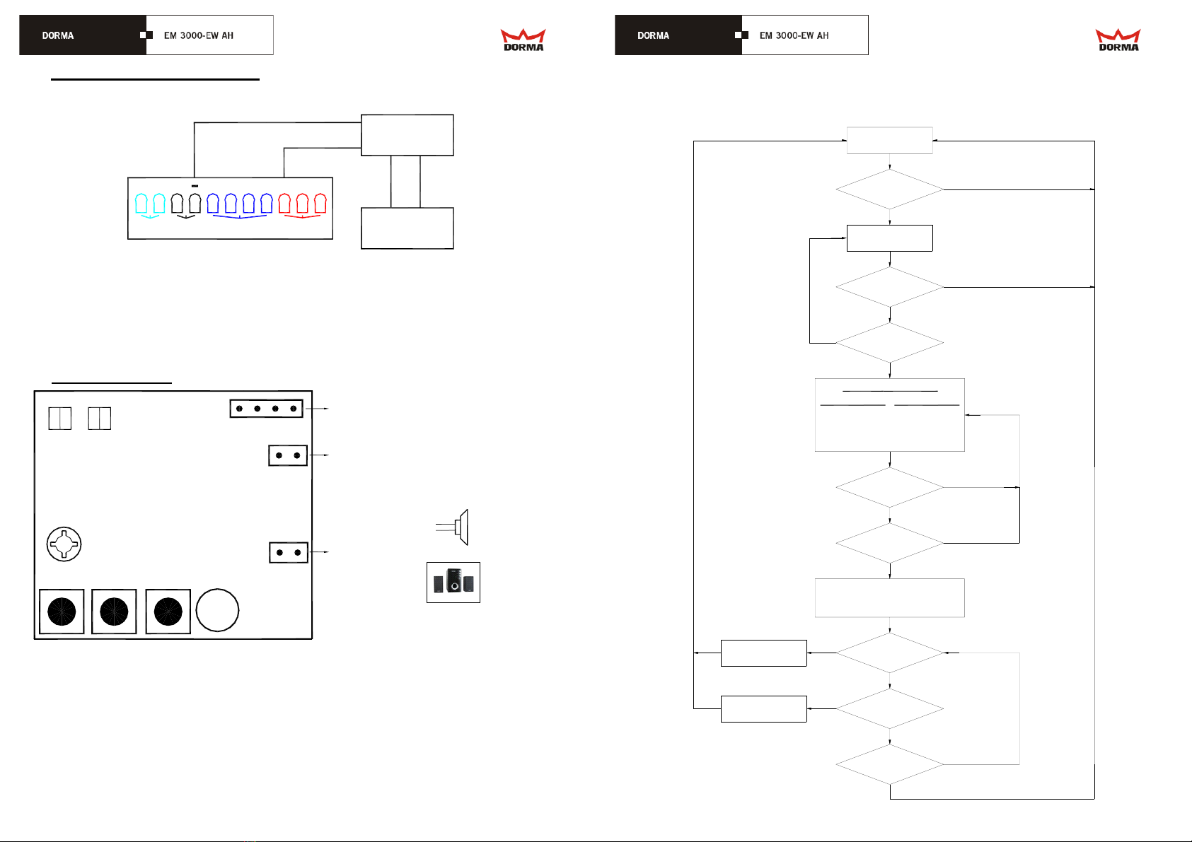
C. EARLY WARNING ALARM FUNCTIONS
In the normal condition, the door is fail safe (power to lock) and locked, the local buzzer is off,
the Local Alarm Relay (DPDT, 1C) is deenergized and the Remote Alarm Relay (SPDT, 2C) is
energized.
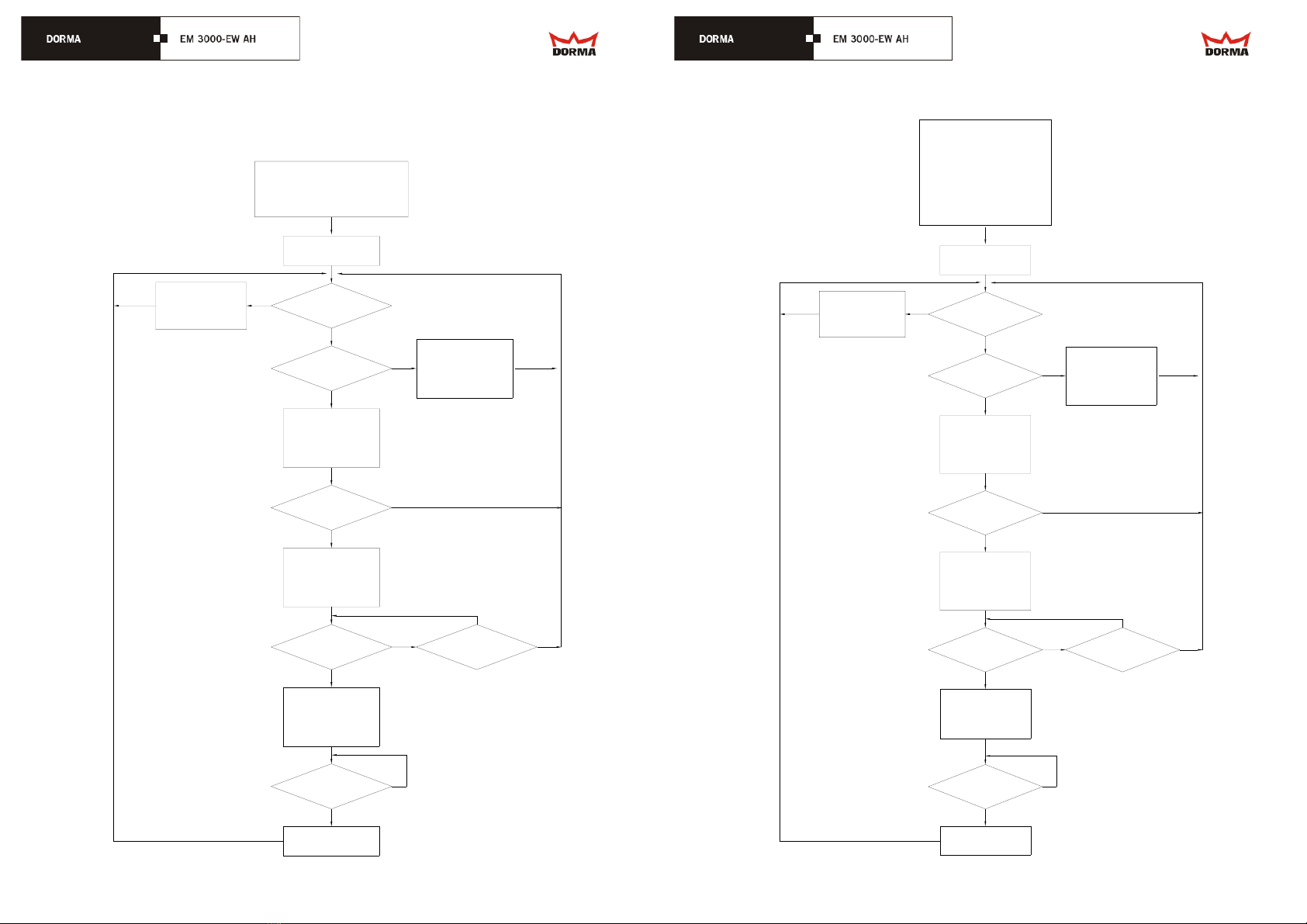
The system will start the alarm sequences by just slightly pushing the door to enter the
Nuisance Delay Period which can be set for 0, 2, 4 or 6 seconds, at the same time the Local
Alarm Buzzer will sound pulsingly and the Local Alarm Relay will be energized, warning that
someone may force to open the secured lock, if that person wants to force to open the
secured lock, he or she must maintain pressure on the door until the end of the Nuisance
Delay Period and if he or she backs off before the time set, both the Local Alarm Buzzer and
the Local Alarm Relay will stop/be deenergized, and revert to normal operation. The purpose
of Nuisance Delay Period is to take the accidental triggering the sequence into consideration.
Once the Nuisance Delay Period time out, the Remote Alarm Period begins and can be set
for 0, 15, 30 seconds or infinity, at the same time the Remote Alarm Relay will be deenergized
and the Local Alarm Buzzer will go from pulsing to steady.
Once the Remote Alarm Period time out, both the Local Alarm Buzzer and the Local Alarm
Relay will stop/be deenergized. At the same time the Remote Alarm Relay will be energized.
Please note there will be no Remote Alarm period time out if the Remote Alarm Period is set
to infinity.
Once the Remote Alarm Period is time out, system will be reset to the normal condition when
the Reset Switch Input is CLOSE. That is, after reset, the system will start the alarm
sequences if someone pushes the door again. Please note system can be reset only after
Remote Alarm Period is time out. For infinity setting, reset is functional only after Remote
Alarm Period reaches 90 seconds.

EARLY WARNING ALARM SYSTEM STATUS
System
Status Light Panel Local
Buzzer Voice Local
Alarm Relay Remote
Alarm Relay
Door Open Red on OFF OFF OFF OFF
Lock
Locked
Green blinks
every 5
seconds OFF OFF OFF ON
Nuisance
Delay
Period
Red blinking
(fast) Sound
pulsingly Voice I ON ON
Remote
Alarm
Period
Red blinking
(slowly) Sound
steady Voice IV ON OFF
Remote
Alarm
Time Out
Red/Green
blinking
alternately OFF OFF OFF ON
Force to
Open Red blinking
(fast) Sound
pulsingly Voice IV ON OFF
Exit Switch
to Open Red on OFF Voice III OFF OFF
Voice I: Unauthorized personnel prohibited.
(Max. 4 second periods for Voice I)
Voice II: The emergency exit system has been activated, the door will unlock in a moment.
(Max. 8 second periods for Voice II)
Voice III: The door is now unlocked, please exit.
(Max. 8 second periods for Voice III)
Voice IV: Illegal intruder. The security alarm is activated. Security personnel has been
alerted and would arrive momentarily.
(Max. 10 second periods for Voice IV)
Voice Module is optional.
“Force to Open” can only be turned off by switching off the system power.
After “Exit Switch to Open” is timeout, system is back to the normal condition.
Local
Normal Condition Nuisance Delay Remote Alarm Reset to
(Power on & Door Locked) Period Normal Condition
Remote
Local Buzzer
Voice Message Voice Message I Voice Message IV
Period
0 ~ 6 Seconds
Alarm Relay
Alarm Relay
energized
deenergized
energized
deenergized
on
off
Early Warning Alarm Functions
(Power on & Door Locked)
Exit Switch to Open
Force to Open
Can be "Exit Switch to Open" in this period - Voice Message III
After "Exit Switch to Open" is timeout, system will be back to the normal condition
Remote Alarm
Timeout
0 or 15 or 30 or
Infinite Seconds
Can be "Force to Open" in this period - Voice Message IV

7
DIP SWITCH SETTING FOR SECURITY DOOR LOCK
1
ON
0 Sec.
Nuisance Delay
Dip Switch 1&2 234
2 Sec. 4 Sec. 6 Sec.
0 Sec.
Remote Alarm
Dip Switch 3&4
15 Sec. 30 Sec. Infinity
5 1
ON
2345
1
ON
23451
ON
2345 1
ON
2345 1
ON
2345
1
ON
23451
ON
2345
D. POWER REQUIREMENTS
Power Input Accept power in the range of 12 ~ 30 VDC
Power Consumption 12 VDC – MAX. 0.55A. (with all relays on, no buzzer)
24 VDC – MAX. 0.27A. (with all relays on, no buzzer)
Output Relays
Local Alarm Output –
Form C: 1.0A 120VAC, 2A 30VDC.
Remote Alarm Output –
2 Form C: 1.0A 120VAC, 2A 30VDC.
Wires Requirement
12 ~ 30 VDC Power Input – 2 wires.
Local Alarm Relay Output – 1 x 3 wires.
Remote Alarm Relay Output – 2 x 3 wires.
Reset Input – 2 wires.
Motion Detector Input – 2 wires.
Voice Control Output – 4 wires.
Request to Exit Input – 2 wires.
9 VDC/Max 1A Power Output – 2 wires.
9 VDC/Max 100mA Output to Buzzer – 2 wires.
Operating Temperature -10 to +60 degree C.
E. OTHER FUNCTIONS
Motion Detector Input
(MD)
Normally Open.
These two terminal block inputs are used for Delay
Egress Function. The system will start the delay
sequences only when these two inputs are shorted.
Voice Control Output
(S2, S1, G, 5V) Four terminal block outputs to control Voice Module.
Request to Exit Input
(EXIT)
Normally Open.
The lock will release for 5 seconds when these two
terminal block inputs are momentarily shorted, and will
release all the time as long as these two terminal block
inputs are shorted.
Reset Switch Input
(RST) Reset Switch Input from OPEN to CLOSE will reset the
system back to the normal condition.
9 VDC Power Output System provides 9 VDC/Max. 1A output.
Low Voltage Detection Jumper selectable to release the lock when system
detects 10 VDC low voltage.
Remote Alarm Relay “off” Remote Alarm Relay is off only “when lock is released” or
“when lock is going to be released” or “when lock might
be forced to be released”.
F. SETTINGS & WIRINGS
1
ON
EXIT
Local
2345
Alarm
Remote
Alarm
RST NC NOCNC NOC
MD S1 5V NC NOCS2DC G
BZ1
W1
remote B
localremote A
MAG
W2
R B G
HIC
JP
R B G
LED
voice module
motion
detector power
exit
switch reset
switch
BZ1: 9 VDC output to Buzzer.
MAG: connect to magnet.
HIC: connect to Hall IC.
LED: connect to bi-color LED.
W1: open to enable low voltage detection.
short to disable low voltage detection.
W2: connect to micro switch.
JP: short to connect 9 VDC to C on remote B.

G. CAMERA WIRING DIAGRAM
9V Camera
Monitor
video GND
video GND
GND
+ 9VDC
Note: 1. System can provides one +9VDC output on "remote B" NC
if JP on the PCB is short.
2. Please short JP and connect Camera positive terminal to
MD S1 5V NC NOCS2DC G
remote Bvoice module
motion
detector power
NC on "remote B". 1
H. VOICE MODULE
B R
PB1 PB2 PB3
MIC
Speaker
G Y B R
LED2
LED1
R B
ANA
Grn
Red
Red
Grn
Connect to HD1 S2/S1/G/5V 4-wire connector
on EW5700 PCB or S2/S2/G/5V termianl blocks
Connect to computer earphone output.
Connect to speaker.
Turn closewisely to
increase the voice.
on EW3500 PCB.
(No Polarity)
(No Polarity) or
Max. 1W
Speaker with
Speaker
Power Source
There are 3 ways to record the messages to the voice module:
When the Voice Module is in the stage of starting recording, user can record the voice
message by speaking to the microphone on the voice module or by connecting ANA to
computer earphone output and playback the voice message thru such as Windows Media
Player.
The messages can also be recorded by programming the Voice Messages directly to the chip
thru programmer.
Flow Chart for Voice Module
Y
PB1 or PB2
Pushed?
PB3 Pushed ?
N
Y
Select Message Segment
LED2 Status
N
N
LED1 Red/Grn
LED2 OFF/OFF
PB3 Pushed ? Y
OFF/OFF
Red/OFF
OFF/Grn
Red/Grn
Segment Selected
1 <4 Seconds>
2 <8 Seconds>
3 <8 Seconds>
4 <10 Seconds>
PB1 or PB2
Pushed?
N
Y
Y
PB3 Pushed ? N
LED1 OFF/OFF
Segment Confirmed
LED2 indicate the selected segment
N
PB1 Pushed ?
N
PB2 Pushed ?
PB3 Pushed ? N
Y
LED1 Red/OFF
START RECORDING Y
LED1 OFF/Grn
PLAYBACK Y
NOTE:
Segment 1/2/3/4 is limited to
4/8/8/10 seconds respectively.
INITIAL
LED1/LED2 ALL OFF
NOTE:
Push PB1/PB2 to increment/decrement
the segment number.
NOTE:
Push PB1/PB2 to increment/decrement
the segment number.
Push PB3 to return to the initial.

I. FLOW CHARTS
Flow Chart for STANDRD BUILDING CODE
N
Y
LEDR Blinking Fast
Local Alarm On
Remote Alarm On
Buzzer Pulsing
Nuisance Delay
Time Out ?
Dip Switch Setting
Dip1- On: 15 Sec. Off: 30 Sec.
Dip2/Dip3- On/On: 0 Second.
Dip4- On.
Power On
Locked ?
Door Pushing ?
LEDR Off
LEDG Blinks every 5S.
Local Alarm Off
Remote Alarm On
Y
N
Y
LEDR Blinking Slowly
Local Alarm On
Remote Alarm Off
Buzzer On
Release Delay
Time Out ?
Y
LEDR/G Blinking Alt.
Local Alarm Off
Remote Alarm Off
Lock Release
NStill Locked ?
N
LEDR On
Local Alarm Off
Remote Alarm Off
Reset to Relock
?
Y
Relock
N
Y
Dip1- Release Delay can be
15 or 30 seconds.
Dip2/Dip3- Nuisance delay not allowed.
Relock occurs only when Reset
Switch Input from open to close.
NOTE:
NOTE:
N
Buzzer Off
Buzzer Off
Flow Chart for NFPA 101
N
Y
LEDR Blinking Fast
Local Alarm On
Remote Alarm On
Buzzer Pulsing
Nuisance Delay
Time Out ?
Dip Switch Setting
Dip1- On: 15 Sec. Off: 30 Sec.
Dip2/Dip3- On/On: 0 Second.
On/Off: 1 Second.
Off/On: 2 Seconds
Off/Off: 3 Seconds.
Dip4- On.
Power On
Locked ?
Door Pushing ?
LEDR Off
LEDG Blinks every 5S.
Local Alarm Off
Remote Alarm On
Y
N
Y
LEDR Blinking Slowly
Local Alarm On
Remote Alarm Off
Buzzer On
Release Delay
Time Out ?
Y
LEDR/G Blinking Alt.
Local Alarm Off
Remote Alarm Off
Lock Release
NStill Locked ?
N
LEDR On
Local Alarm Off
Remote Alarm Off
Reset to Relock
?
Y
Relock
N
Y
Dip1- Release Delay can be
15 or 30 seconds.
Dip2/Dip3- Nuisance delay permitted
up to 3 seconds.
Relock occurs only when Reset
Switch Input from open to close.
NOTE:
NOTE:
N
Buzzer Off
Buzzer Off

Flow Chart for UNIFORM BUILDING CODE
N
Y
LEDR Blinking Fast
Local Alarm On
Remote Alarm On
Buzzer Pulsing
Nuisance Delay
Time Out ?
Dip Switch Setting
Dip1- On: 15 Seconds
Dip2/Dip3- Off/On: 2 Seconds.
Dip4- On.
Power On
Locked ?
Door Pushing ?
LEDR Off
LEDG Blinks every 5S.
Local Alarm Off
Remote Alarm On
Y
N
Y
LEDR Blinking Slowly
Local Alarm On
Remote Alarm Off
Buzzer On
Release Delay
Time Out ?
Y
LEDR/G Blinking Alt.
Local Alarm Off
Remote Alarm Off
Lock Release
NStill Locked ?
N
LEDR On
Local Alarm Off
Remote Alarm Off
Reset to Relock
?
Y
Relock
N
Y
Dip1- Release Delay 15
seconds only.
Dip2/Dip3- Nuisance delay must be
set 2 seconds.
Relock occurs only when Reset
Switch Input from open to close.
NOTE:
NOTE:
N
Buzzer Off
Buzzer Off
Flow Chart for BOCA
N
Y
LEDR Blinking Fast
Local Alarm On
Remote Alarm On
Buzzer Pulsing
Nuisance Delay
Time Out ?
Dip Switch Setting
Dip1- On: 15 Sec. Off: 30 Sec.
Dip2/Dip3- On/Off: 1 Second.
Dip4- Off.
Power On
Locked ?
Door Pushing ?
LEDR Off
LEDG Blinks every 5S.
Local Alarm Off
Remote Alarm Off
Y
N
Y
LEDR Blinking Slowly
Local Alarm On
Remote Alarm Off
Buzzer On
Release Delay
Time Out ?
Y
LEDR/G Blinking Alt.
Local Alarm Off
Remote Alarm Off
Lock Release
NStill Locked ?
N
LEDR On
Local Alarm Off
Remote Alarm Off
Relock Delay
Starts ?
Y
Relock
N
Y
Dip1- Release Delay can be
15 or 30 seconds.
Dip2/Dip3- Nuisance delay must be
set at 1 second.
30 seconds Relock Delay starts only
when Reset Switch Input from open
to close. At this stage, door close.
NOTE:
NOTE:
N
Dip4- Relock Delay required
set at 30 seconds.
Y
Relock Delay
Stops ?
N
30 seconds Relock Delay stops only
when Reset Switch Input from close
to open. At this stage, door open.
NOTE:
Y
Relock Delay
T/O ?
N
Buzzer Off
Buzzer Off

Flow Chart for NATIONAL BUILDING CODE
N
Y
LEDR Blinking Fast
Local Alarm On
Remote Alarm On
Buzzer Pulsing
Nuisance Delay
Time Out ?
Dip Switch Setting
Dip1- On: 15 Seconds
Dip2/Dip3- On/On: 0 Second.
Dip4- On.
Power On
Locked ?
Door Pushing ?
LEDR Off
LEDG Blinks every 5S.
Local Alarm Off
Remote Alarm On
Y
N
Y
LEDR Blinking Slowly
Local Alarm On
Remote Alarm Off
Buzzer On
Release Delay
Time Out ?
Y
LEDR/G Blinking Alt.
Local Alarm Off
Remote Alarm Off
Lock Release
NStill Locked ?
N
LEDR On
Local Alarm Off
Remote Alarm Off
Reset to Relock
?
Y
Relock
N
Y
Dip1- Release Delay 15
seconds only.
Dip2/Dip3- Nuisance delay not allowed
Relock occurs only when Reset
Switch Input from open to close.
NOTE:
NOTE:
N
(for CANADA)
Buzzer Off
Buzzer Off
Flow Chart for BURGLAR ALARM
N
Y
LEDR Blinking Fast
Local Alarm On
Remote Alarm On
Buzzer Pulsing
Nuisance Delay
Time Out ?
Power On
Locked ?
Door Pushing ?
LEDR Off
LEDG Blinks every 5S.
Local Alarm Off
Remote Alarm On
Y
N
Y
LEDR Blinking Slowly
Local Alarm On
Remote Alarm Off
Buzzer On
Alarm Period
Time Out ?
Y
LEDR/G Blinking Alt.
Local Alarm Off
Remote Alarm On
NStill Locked ?
N
LEDR On
Local Alarm Off
Remote Alarm Off
Reset ?
Y
System Reset
N
Y
Dip1/Dip2-
Remote Alarm Period can
be infinity.
Dip3/Dip4-
Nuisance Delay permitted
up to 6 seconds.
System reset occurs only when
Reset Switch Input is close.
NOTE:
NOTE:
N
Dip Switch Setting
Dip1/Dip2- On/On: 0 Second.
On/Off: 2 Seconds.
Off/On: 4 Seconds.
Off/Off: 6 Seconds
Dip3/Dip4- On/Off: 15 Seconds.
Off/On: 30 Seconds.
Off/Off: Infinity
On/On: 0 Second.
Buzzer Off
Buzzer Off
Remote
Table of contents
Other Dorma Lock manuals

Dorma
Dorma ARCOS Office User manual

Dorma
Dorma EM 7500-D AM User manual

Dorma
Dorma EM Series User manual

Dorma
Dorma CL853 User manual

Dorma
Dorma ARCOS Office User manual

Dorma
Dorma G-EMF Manual

Dorma
Dorma Duo OFFICE 712 User manual

Dorma
Dorma Studio Classic User manual

Dorma
Dorma Studio Rondo User manual

Dorma
Dorma CL700 User manual

Dorma
Dorma M9000 User manual

Dorma
Dorma SVP 22 Series User manual

Dorma
Dorma ARCOS Studio User manual

Dorma
Dorma C300 User manual

Dorma
Dorma EML320 User manual

Dorma
Dorma EM Series User manual

Dorma
Dorma ES 110-4 Series User manual

Dorma
Dorma PT 41 User manual

Dorma
Dorma EM 15000-D AM User manual

Dorma
Dorma EM Series User manual