Dorma EML320 User manual

Pre-Installation Instructions
1. This product must be installed according to all applicable
building and life safety codes.
2. Due to the variety of mounting configurations available with
this product, a survey and assessment of the physical area
in which the product will be installed must be performed.
3. The door frame must be inspected and deemed structurally
sound prior to installation of the electromagnetic lock. The
structural integrity of the mounting surfaces must be strong
enough to meet or exceed the holding force of the product.
4. The product must be protected from potential damage due
to intruders or tampering.
5. The product should be installed in a location that will not
hinder or create a potential safety hazard to authorized
personnel accessing the protected area.
6. Because electromagnetic locks are used in a variety of
applications and different door frame configurations, an
experienced installer with knowledge of this product must
make a determination of the optimal mounting method for
this specific application.
7. The components, hardware, installation instructions and
mounting template included with this product are intended
for use on outswinging doors.
8. Do not install this product on the exterior of buildings.
9. Do not use as a doorstop. This will void warranty.
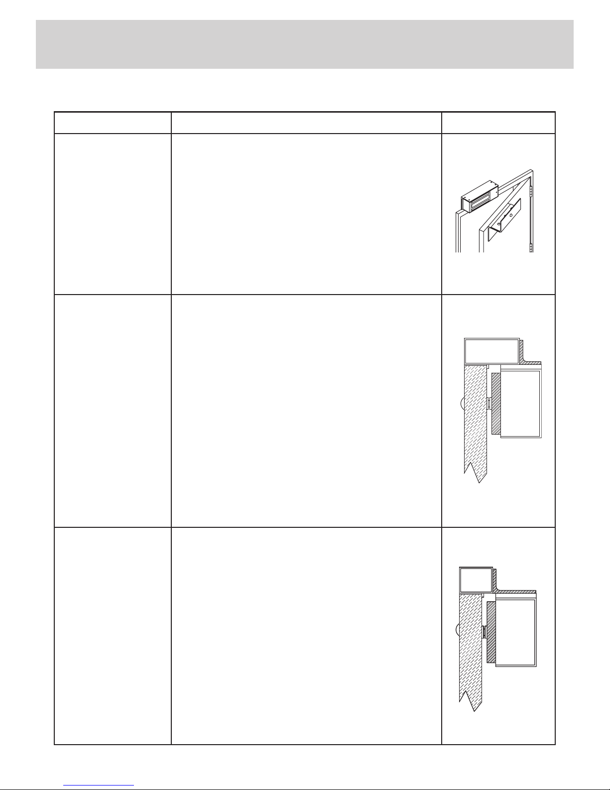
10. Separate accessories not included with this product must be
used in the following applications:
frame header to mount the lock
not thick enough to allow the product to be installed
installation of the armature plate at a proper height
mounted low enough to meet the magnet surface
Refer to the Product Accessories Guide section of
Accessories may impact holding force.
11.
experienced installer with knowledge of this product.
NOTE:
be applied to all screws during installation to reduce chance of
screws loosening over extended time.
Installation Instructions
1.
on the installation template included with the product.
NOTE: During installation of the armature plate to the door it is
essential that the armature plate remains movable. The armature
not aligned with the magnet surface, the lock may lose holding
force or not lock at all.
The head of the armature mounting bolt ships with a rubber
the surface of the armature plate. This is to allow the washer
to expand when power is removed and break the air vacuum
removed or trimmed the lock will appear to have some holding
force even when power is removed.
for the armature plate bolt and the four captive electromagnetic
WARNING: Improper installation, maintenance, inspection or
usage of the product or any related accessories or parts may cause
the electromagnetic lock, armature plate and associated hardware
to disengage and fall, causing serious bodily injury and property
damage. Dorma will not be liable to the installer, purchaser, end
user or anyone else for damage or injury to person or property due
to improper installation, care, storage, handling, maintenance,
inspection, abuse, misuse or act of God or nature involving this
product or any related accessories or parts.
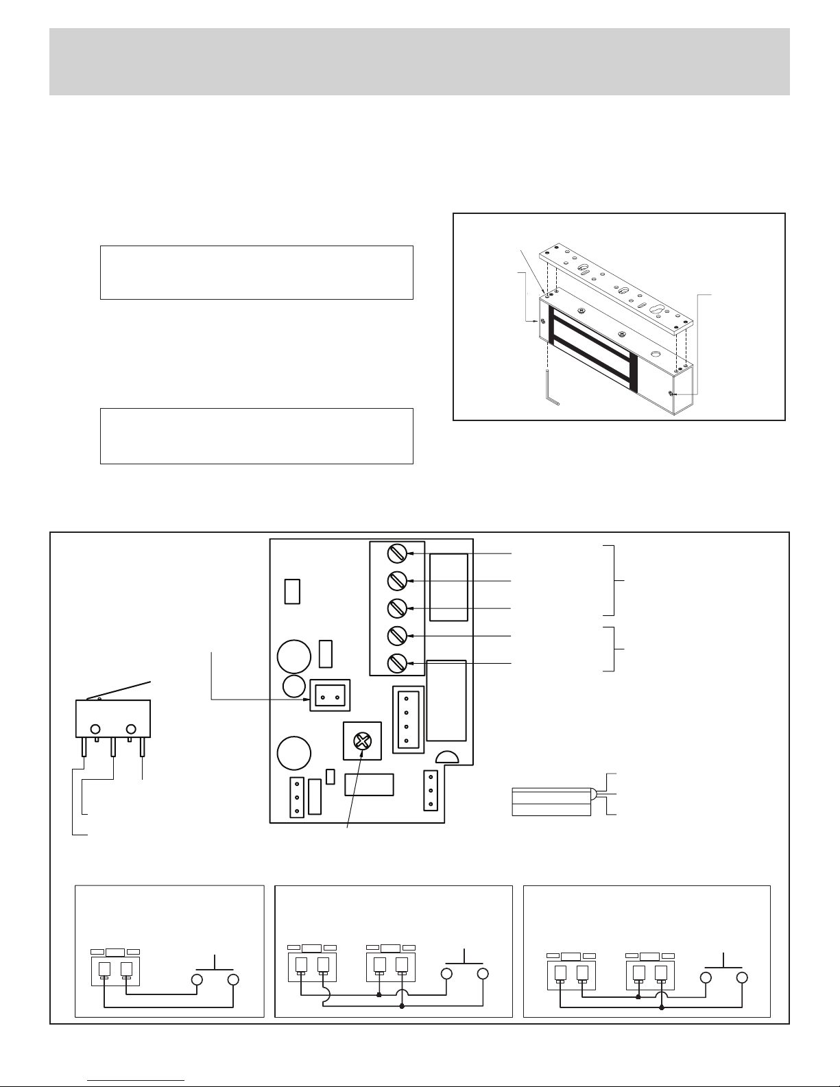
2. Route the power supply connecting wire through the door
frame and into the wire access hole in the top of the magnet
housing. Connecting wire should be of sufficient gauge for the
lock being installed and the distance being run. See table on
Electromagnetic Locks
INSTALLATION
EML310/EML320

EML310 & EML320 Electromagnetic Lock Installation Instructions (Continued)
2
3.
4. Delayed Relock Feature
The delayed relock feature can be used to momentarily
release the lock and keep it unlocked for a time period from
zero seconds.
NOTE: The clockwise direction is consistent for single and
double door models.
possible lock malfunction.
has been removed.
5. Anti-Tamper Feature
Two screws prevent insertion of an Allen wrench into the
captive mounting screw opening on the bottom of the lock.
wiring cavity cover. The mounting plate cannot be separated
from the lock without removing these two screws.
Fig. 2 – Lock Mounting
feature screw
feature and
wiring cavity
screw
Captive
mounting
screw
J2 J2
Two EML310 Locks to release together
using the delayed relock feature.
Blue Wires
N/O
Momentary Switch
Blue Wires
J2
N/O
Momentary Switch
Single lock to release using
the delayed relock feature.
J2 J2
Blue Wires
Both sides of an EML320 Lock to release
together using delayed relock feature.
Left circuit board Right circuit board N/O
Momentary Switch
DELAY
J2
RW1
NORMALLY OPEN
MAG
LED 1
NO NC C
–+
NORMALLY CLOSED
COMMON
COMMON GROUND
12/24VDC INPUT
Optional BA Sensor SPDT
Output contacts rated for
max 1.25 Amp at 24 VDC
Lock powered from a Listed
filtered and regulated
DC Power Supply
Standard DP reed switch contacts rated at
0.20 Amp at 12 VDC and 0.12 Amp at 24VDC
RED: NORMALLY CLOSED
GREEN: NORMALLY OPEN
BLACK: COMMON
RED STRIPED: NORMALLY CLOSED
GREEN STRIPED: NORMALLY OPEN
BLACK STRIPED: COMMON DELAY RELOCK ADJUSTMENT
Turn clockwise to increase delay on EML310 single and both sides of EML320 double door model.
Fig. 1 – Lock Wiring
See Optional Delayed
Relock Options Below
Optional Delayed Relock Options - for use in a delayed-egress locking system, relock must be set to 0 seconds.

EML310 & EML320 Electromagnetic Lock Installation Instructions (Continued)
3
6. To Ensure Instant Release All switching devices must be
wired in between the DC power source and the positive
supply line will not allow the lock to release immediately.
suppression and do not require any additional suppression to
be added during installation.
Lock Monitoring Options
SWITCH
+
-
INCORRECT
CORRECT
+
-
SWITCH
FILTERED DC SUPPLY
FILTERED DC SUPPLY
SWITCH
+
-
INCORRECT
CORRECT
+
-
SWITCH
FILTERED DC SUPPLY
FILTERED DC SUPPLY
Fig. 3 – Power Connections
BA – Bond Alert Sensor
This option can detect the quality of the locking bond between the
surface of the magnet and the armature plate. The sensitivity of
Due to the sensitivity of this option and the necessity to maintain
a reliable locking bond, these surfaces must be kept free of
contaminating materials. Both the lock surface and the armature
Alignment of armature plate and magnet is required to ensure
mounted on the bottom of the lock housing.
The Security Condition Sensor is available as a factory ordered
option only.
DP – Door Position Sensor
The DP option monitors the position of the door upon which the
lock is installed. A SPDT reed switch mounted within the lock
cavity eliminates the need for extra sensors to be installed on the
door for notification of security or access control systems. The DP
plate for signaling the reed switch in the housing when the door
is closed. Care should be taken during the final testing of the lock
to ensure that the DP option is operating in the desired manner.
The Door Position Sensor may be ordered as either a factory
are added together as a field accessory, they must be ordered as
a combination to ensure proper fit.

EML310 & EML320 Electromagnetic Lock Installation Instructions (Continued)
Listings
Canada.
Additionally, these products are qualified components
unauthorized egress.They are designed to release automatically
in case of a power failure or upon activation of an automatic fire
alarm system wired to the power supply fire panel relay.
The Following Conditions of Acceptability Apply:
1)
Arrangements which are installed in accordance with the
2)
3) The suitability of the lead wires is to be evaluated per the
4)
control panel, the wiring from the control unit to this product
5)
6)
These models have also been independently
Holding Force:
Cycle Test:
CAMERA-READY LOGOTYPE FOR TYPE L AND TYPE R LISTING MARKS FOR CANADA AND THE U.S.
These Marks are registered by Underwriters Laboratories Inc.
The minimum height of the registered trademark symbol ® shall be 3/64 of an inch. When the overall diameter of the
UL Mark is less than 3/8 of an inch, the trademark symbol may be omitted if it is not legible to the naked eye.
The font for all letter forms is Helvetica Condensed Black, except for the trademark symbol ®, which is
Helvetica Condensed Medium. No other fonts are acceptable.
Please Note:
The word "MARINE" should only be used for UL Classified marine products.
200-195F 20M/11/97
4
Power Supply:
NOTE:
Specifications
MECHANICAL (
:
Standard Armature Plate Dimensions:
ENVIRONMENTAL:
Circuit board operating temperature:
ELECTRICAL:
Voltage:
Current:
NOTE:
BA Output Relay*:
DP Reed Switch*:
*
(power factor ≥
NOTE: Specifications may change without notice.
Voltage EML310 EML320

EML310 - EML320 Series Troubleshooting Guide
Problem Solution
Cannot remove the lock mounting bracket from top of
magnet for installation.
screwdriver or set of pliers but door will not lock.
of power.
EML310 & EML320 Electromagnetic Lock Installation Instructions (Continued)
5
Inspection and Maintenance
This product and all related accessories or parts must be inspected
and maintained on a quarterly basis. Contacting surfaces of the
electromagnetic lock and armature plate must be kept free of
contaminating materials. Surfaces must be cleaned periodically with
All mounting fasteners must be inspected on a quarterly basis.
movement but the plate will feel secure when grasped at the bolt.
There should be no movement to the mounting bracket or housing
of the electromagnetic lock.
the armature plate bolt and the four captive electromagnetic lock
mounting screws.
WARNING: Improper installation, maintenance, inspection or usage
of the product or any related accessories or parts may cause the
electromagnetic lock, armature plate and associated hardware
to disengage and fall, causing serious bodily injury and property
damage.
For product support, parts and
ordering information contact:
DORMA
Dorma Drive, Drawer AC
Reamstown, PA 17567 USA
Phone: (717) 336-3881
Fax: (717) 336-2106
Toll Free: (800) 523-8483
Email:[email protected]
Check connections at power supply, connected releasing devices,
lock terminals and lock circuit board to magnet core.
Check delayed relock wiring and time setting.
Check that the momentary switch does not include a shunted light option.
Check to see that armature plate is correctly aligned with the
turn of the armature plate mounting bolt and check for alignment.
This generally indicates that the lock is either operating on AC voltage
or there is some AC voltage present in the DC supply. A properly
filtered and regulated DC power supply is required to achieve optimal
operation from the lock.
AC power supply voltage.
removed or damaged.
Check that switching device interrupts the positive wire and not the
Remove any Diodes or other suppression devices that may be installed.

Product Accessories Guide
Required wherever there is insufficient space on the frame header to
Available in several different sizes and finishes.
Part Usage Example
EML310 & EML320 Electromagnetic Lock Installation Instructions (Continued)
6
the underside of an angle bracket mounted on the frame. Armature plate
place where there is insufficient frame depth to mount the lock.
Available in several different sizes and finishes.
Angle Bracket
Accessories may impact holding force.

Part Usage Example
EML310 & EML320 Electromagnetic Lock Installation Instructions (Continued)
7
a single lock. The Split Armature plates are half the length of a standard
lock centered on the frame between the doors.
NOTE:
Split Armature
Plates
where the door stop of the frame is not thick enough to allow a lock to
be installed.
Available in several different heights and widths.
lowered then a spacer bar can be used to lower the lock from the frame.
Available in several different heights.
Spacer Bars
low enough to meet the magnet surface. The armature holder can be
mounted to whatever frame is available and the armature plate in turn
mounted to the holder.

EML310 & EML320 Electromagnetic Lock Installation Instructions (Continued)
Wire Gauge Selections
8
Total One Way
Length of 1/4A 1/2A 3/4A 1A 1-1/4A 1-1/2A 2A 3A
Wire Run (ft.)
100 20 18 16 16 14 14 12 10
150 20 16 14 14 12 12 10 --
200 18 16 14 12 12 10 10 --
250 18 14 12 12 10 10 -- --
300 16 14 12 10 10 -- -- --
400 16 12 10 10 -- -- -- --
500 14 12 10 -- -- -- -- --
750 12 -- -- -- -- -- -- --
1000 12 -- -- -- -- -- -- --
Total One Way
Length of 1/4A 1/2A 3/4A 1A 1-1/4A 1-1/2A
Wire Run (ft.)
100 18 16 14 12 12 10
150 16 14 12 10 10 --
200 16 12 10 10 -- --
250 14 12 10 -- -- --
300 14 10 -- -- -- --
400 12 10 -- -- -- --
500 12 -- -- -- -- --
750 10 -- -- -- -- --
Load Current @24V
Load Current @12V
This manual suits for next models
1
Table of contents
Other Dorma Lock manuals

Dorma
Dorma SVP 22 Series User manual

Dorma
Dorma EM Series User manual

Dorma
Dorma G-EMF Manual

Dorma
Dorma ES 110-4 Series User manual

Dorma
Dorma Duo OFFICE 712 User manual

Dorma
Dorma ARCOS Office User manual

Dorma
Dorma EM 3000-EW AH User manual

Dorma
Dorma EM Series User manual

Dorma
Dorma Studio Classic User manual

Dorma
Dorma EM Series User manual

Dorma
Dorma EM 15000-D AM User manual

Dorma
Dorma ARCOS Studio User manual

Dorma
Dorma CL700 User manual

Dorma
Dorma PT 41 User manual

Dorma
Dorma CL853 User manual

Dorma
Dorma EM 7500-D AM User manual

Dorma
Dorma M9000 User manual

Dorma
Dorma EM Series User manual

Dorma
Dorma DB600 Series Guide

Dorma
Dorma ARCOS Office User manual