manuals.online logo
Brands
  1. Home
  2. •
  3. Brands
  4. •
  5. Dorma
  6. •
  7. Lock
  8. •
  9. Dorma ARCOS Office User manual

Dorma ARCOS Office User manual

ARCOS Office
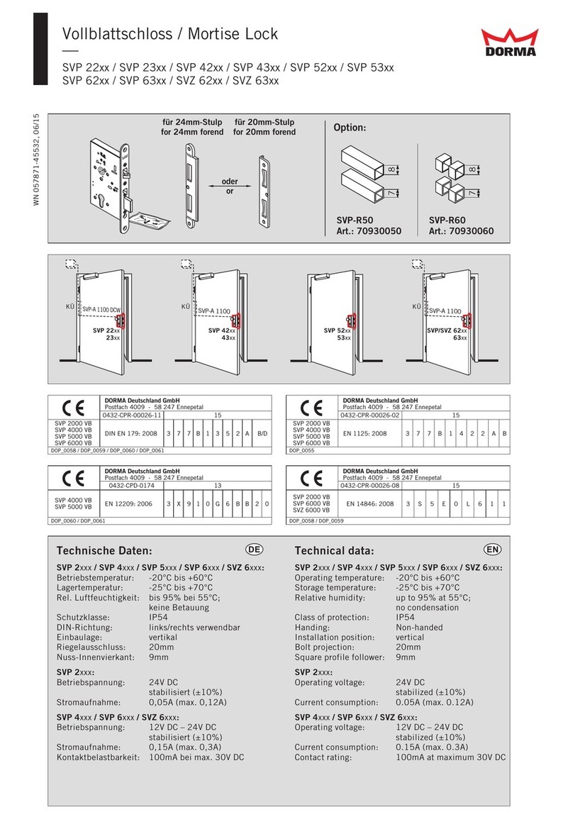
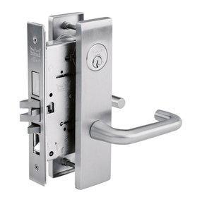
Montageanleitung Schloss / Gegenkasten
Sie erhalten das Schloss mit Gehäuse in montiertem
Zustand. Bitte halten Sie die Klemmflächen für das
Schloss und den Gegenkasten auf dem Glas fettfrei.
1. Montage Schloss (G)
Senkschrauben (4) an der Stulpseite herausdrehen.
2. Kappe (3) abnehmen.
3. Die sichtbar werdenden zwei Senkschrauben
M6x30 (5) mit Sechskantschlüssel SW 4 herausdre-
hen und Schlossplatte (6) mit Schloss (7) von der
Gegenplatte (9) abnehmen.
4. Vor der Montage des Schlosses den beigefügten
Alu-Streifen (8) auf der Bandseite auf das Glas kle-
ben. Der Streifen verhindert den Blick in das Schloss
an der freien Glaskante. Nach der Montage des
Schlosses die Überstände abschneiden.
5. Schlossplatte und Schloss mit Gegenplatte auf das
Glas schrauben.
Anzugsmoment der Schrauben = 5 Nm
6. Kappe (3) mit Senkschrauben (4) befestigen und
Drückerpaar (1) montieren. Um eine spätere Demon-
tage eines Rosettendrückers zu gewährleisten, sollte
eine evtl. Klipsnase an der Drückerunterrosette (2)
möglichst nach oben zeigen.
Achtung:
PZ Schloss besitzt eine spezielle Klemmnuss, welche
sich durch eine besonders stramme Vierkant Passung
auszeichnet - leichter Druckpunkt muss überwunden
werden.
7. Montage Gegenkasten (F)
Schlauchabschnitte (16) in Glasbohrungen stecken.
Klemmplatte (15) und Gegenplatte (17) mit Senk-
schrauben M6x30 (14) (Sechskant-schlüssel SW4)
durch Glasbohrungen verschrauben. Abdeckkappen
(13) und (18) an Stiftseite (12) in Klemmplatte und
Gegenplatte einhaken. Mit Senkschrauben (10) Ab-
deckkappen (13), incl. Fallenschutzblech (11) und
Abdeckkappe (18) festschrauben.
Legende zu den Abbildungen
(A) Bandseite
(B) Bandgegenseite
(C) Abbildung zeigt Schloss DIN links
(D) Abbildung zeigt Schloss DIN rechts
(E) Glasbohrungen
(F) Gegenkasten, DIN rechts
(G) Schloss, DIN links
ARCOS Office
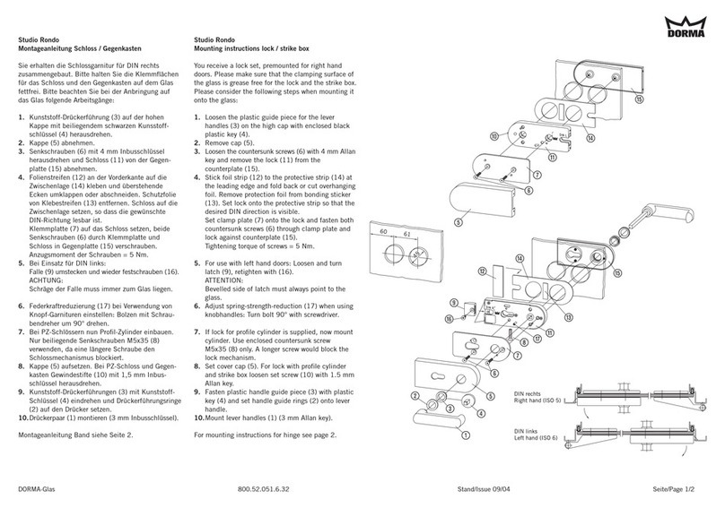
Mounting instructions Lock / strike box
You receive a completely assembled lock. Please
make sure that the clamping surface of the glass is
grease free for the lock and the strike box.
1. Mounting lock (G)
Loosen the countersunk screws (4) at the latch side.
2. Remove cap (3).
3. Loosen the now visible two countersunk screws
M6x30 (5) with a 4 mm Allan key and remove lock
plate (6) with lock (7) from counterplate (9).
4. Before mounting the lock, stick the enclosed
aluminium strip (8) at the interior side onto the glass.
The strip prevents the sight into the lock at the short
side of the backplate. After having mounted the lock,
cut the overhanging strip off.
5. Screw lock plate and lock with counterplate
against the glass.
Tightening torque of screws = 5 Nm
6. Fasten the cap (3) with countersunk screws
(4) and mount lever handles (1). To ensure a later
dismantling of a rose lever, a clipping catch should if
possible be seen on the topside of the lever rose base
(2).
Attention:
The profile cylinder lock has a special clamp nut,
which has a tight square fit - light pressure point
must be overcome.
7. Mounting strike box (F)
Put the tube sections (15) into drilled glass holes.
Screw through drilled holes with countersunk screw
M6x30 (13) (4 mm Allan key) clamp plate (14) and
counterplate (16) together. Hook in cover caps (12)
and (17) into clamp plate and counterplate at pin
side (11) and fasten with countersunk screws (10).
Legend for illustrations
(A) interior side
(B) exterior side
(C) Illustration shows lock DIN left hand
(D) Illustration shows lock DIN right hand
(E) drilled glass holes
(F) strike box, DIN right hand
(G) lock, DIN left hand
DORMA-Glas 800.52.057.6.32 Stand/Issue 09/04 Seite/Page 1/2
ARCOS Office
Montageanleitung Band
Bitte halten Sie die Klemmflächen für die Bänder auf
dem Glas fettfrei.
1. Ganzglasflügel in Türrahmen auf 7 mm Platten
stellen (untere Türluft) und seitlich ausrichten.
2. Rahmenteile (10) in Zarge stecken und befestigen.
Hülse (11) aufschieben.
Hinweis:
Beim Aufschraubrahmenteil (10 c) dürfen die Befesti-
gungsschrauben nicht überstehen!
3. Bei Kugellager (9) auf richtige Einbaulage achten.
4. Bandteil (6) auf Rahmenteil schieben, Bolzen (8)
durchstecken und mit Gewindestift (7) sichern.
5. Kunststoff-Schlauchabschnitte (5) in Glasbohrun-
gen stecken. Von der Bandgegenseite her die Klemm-
platte (4) mit Senkschrauben M6x24 (3) (Sechskant-
schlüssel SW4) in Bandteil verschrauben.
Anzugsmoment der Schrauben = 12 Nm
6. Kappe (2) mit Doppelklebeband (1) auf Klemm-
platte (4) aufkleben.
Legende zu den Abbildungen
(E) Glasbohrungen
(I) Band, DIN links
(M) Rahmenteile
Pflege allgemein:
Die Oberflächen der Beschläge sind nicht wartungs-
frei und sollten gemäß ihrer Ausführung gereinigt
werden.
- Für metallische Oberflächen (Eloxaltöne, Edelstahl)
bitte nur geeignete Reiniger ohne Scheuermittelan-
teil verwenden.
- Für lackierte Oberflächen bitte nur entsprechende
lösemittelfreie Reiniger verwenden.
- Messing Oberflächen (ohne Oberflächenschutz)
müssen von Zeit zu Zeit mit geeignetem Pflegemit-
tel behandelt werden, um ein Anlaufen zu vermeiden.
ARCOS Office
Mounting instructions Hinge
Please make sure that the clamping surface of the
glass is grease free for the hinges.
1. Place glass door panel into door frame and set 7 mm
spacer plates (lower clearance), then align sides.
2. Insert frame portions (10) into frame and fix them.
Set cover bush (11).
Please notice:
Screws must not exceed edge of screw-on frame
portion (10 c)!
3. Make sure that the ball bearing (9) is fitted in the
correct way.
4. Slide hinge (6) onto frame portion, insert bolt (8)
and secure it with setscrew (7).
5. Insert the plastic rings (5) into the glass holes.
Fasten clamp plate (4) with countersunk screws
M6x24 (3) (4 mm Allan key) against hinge from the
exterior side.
Tightening torque of screws = 12 Nm
6. Stick cover cap (2) with double sided adhesive
tape (1) onto clamp plate (4).
Legend for illustrations
(E) drilled glass hole
(I) hinge, DIN left hand
(M) frame pivots
General care instructions:
The surface finishes of the fittings are not
maintenance-free and should be cleaned according to
their material and design.
- For metallic surfaces (anodised finishes, stainless
steel) please use appropriate cleaning agents
without abrasive additives only.
- For varnished surfaces please use appropriate
solvent-free cleaning agents only.
- Brass surfaces (without surface protection) have to
be treated with an appropriate maintenance agent
on occasion, to avoid tarnishing.
DORMA-Glas 800.52.057.6.32 Stand/Issue 09/04 Seite/Page 2/2
35.5
45
16
E
I
M
10
6
11
4
2
3
8
5
7
1
9
10c

Other Dorma Lock manuals

Dorma ARCOS Studio User manual

Dorma

Dorma ARCOS Studio User manual

Dorma Studio Rondo User manual

Dorma

Dorma Studio Rondo User manual

Dorma M9000 User manual

Dorma

Dorma M9000 User manual

Dorma G-EMF Manual

Dorma

Dorma G-EMF Manual

Dorma PT 41 User manual

Dorma

Dorma PT 41 User manual

Dorma ARCOS Office User manual

Dorma

Dorma ARCOS Office User manual

Dorma EML320 User manual

Dorma

Dorma EML320 User manual

Dorma EM 3000-EW AH User manual

Dorma

Dorma EM 3000-EW AH User manual

Dorma C500 User manual

Dorma

Dorma C500 User manual

Dorma EM 7500-D AM User manual

Dorma

Dorma EM 7500-D AM User manual

Dorma Studio Classic User manual

Dorma

Dorma Studio Classic User manual

Dorma ES 110-4 Series User manual

Dorma

Dorma ES 110-4 Series User manual

Dorma CL700 User manual

Dorma

Dorma CL700 User manual

Dorma EM Series User manual

Dorma

Dorma EM Series User manual

Dorma Duo OFFICE 712 User manual

Dorma

Dorma Duo OFFICE 712 User manual

Dorma EM Series User manual

Dorma

Dorma EM Series User manual

Dorma SVP 22 Series User manual

Dorma

Dorma SVP 22 Series User manual

Dorma EM 15000-D AM User manual

Dorma

Dorma EM 15000-D AM User manual

Dorma EM Series User manual

Dorma

Dorma EM Series User manual

Dorma CL853 User manual

Dorma

Dorma CL853 User manual

Dorma EM Series User manual

Dorma

Dorma EM Series User manual

Dorma DB600 Series Guide

Dorma

Dorma DB600 Series Guide

Dorma C300 User manual

Dorma

Dorma C300 User manual

Popular Lock manuals by other brands

W Box Technologies 600 LB HOLDING FORCE installation instructions

W Box Technologies

W Box Technologies 600 LB HOLDING FORCE installation instructions

McGrathLocks MLDDDL manual

McGrathLocks

McGrathLocks MLDDDL manual

RCO LockR Battery Replacement

RCO

RCO LockR Battery Replacement

Keyautomation 580EGS1 Instructions for installation and use

Keyautomation

Keyautomation 580EGS1 Instructions for installation and use

elink YL-71 user manual

elink

elink YL-71 user manual

Abus Touch 57 manual

Abus

Abus Touch 57 manual

T'nB MCAV3W instructions

T'nB

T'nB MCAV3W instructions

US Automatic 070510 installation manual

US Automatic

US Automatic 070510 installation manual

Borglocks BL2701 Installation and instruction manual

Borglocks

Borglocks BL2701 Installation and instruction manual

HAMPTON BAY Array Revive installation guide

HAMPTON BAY

HAMPTON BAY Array Revive installation guide

Abus 183AL/45 quick start guide

Abus

Abus 183AL/45 quick start guide

ABA 2909 operation instruction

ABA

ABA 2909 operation instruction

M-TI Plunger Lock quick start guide

M-TI

M-TI Plunger Lock quick start guide

Burtonsafes BURTON DUO DEAD - BOLT User instructions

Burtonsafes

Burtonsafes BURTON DUO DEAD - BOLT User instructions

Blaupunkt ACE400 LOCK instruction manual

Blaupunkt

Blaupunkt ACE400 LOCK instruction manual

Kaba Mas X-09 1F installation instructions

Kaba Mas

Kaba Mas X-09 1F installation instructions

Schlage B-Series installation instructions

Schlage

Schlage B-Series installation instructions

american lock A700 Assembly/disassembly manual

american lock

american lock A700 Assembly/disassembly manual

manuals.online logo
manuals.online logoBrands
  • About & Mission
  • Contact us
  • Privacy Policy
  • Terms and Conditions

Copyright 2025 Manuals.Online. All Rights Reserved.