manuals.online logo
Brands
  1. Home
  2. •
  3. Brands
  4. •
  5. Dormakaba
  6. •
  7. Door Lock
  8. •
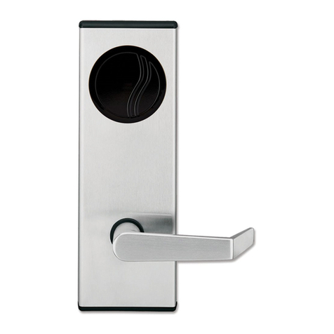
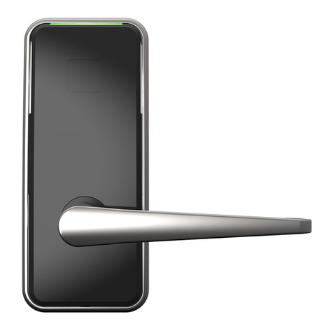
  9. Dormakaba Saffire LX-I User manual

Dormakaba Saffire LX-I User manual

WARNING
Do not remove tape
Slot at the bottom
18
2X
A
4" or
5-1/2"
2 1/8" (54mm ) Hole saw
1" (25mm )
Install long screws
on door stop side
For maximum
security, install
reinforcing plate
Door stop
2
1
3
DO NOT REMOVE TAPE
1 2
14
3
6
7
5
25
26
23
8
13A
21 11 9
18
4
17
2410
12
28
20
2727
13B
22
19
15
16
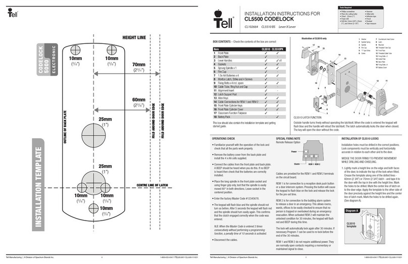
Saffire LX-I Installation Guide for door
thickness 1 3/8" to 2 1/8"
Please read and follow all directions carefully.
1.
This lock is not designed to be used on emergency exit doors
.2.
Carefully inspect glass, door frame, door etc. to ensure the recommended procedure will not cause damage.
3.
dormakaba
standard warranty does not cover damages cause by installation.
Wear safety glasses when making the holes.
4.
All the following operations and testing of the lock to be done with door open.
5.
ADJUST BACKSET OF DEADBOLT
2.
INSTALL DEADBOLT IN DOOR
3.
Safety glasses
•
1/2” (13mm) Chisel
•
1/8” (3mm) Drill Bit
•
5/32” (4mm) Drill Bit
•
1” (25mm) Drill bit or Hole Saw
•
2 1/8” (54mm) Drill bit or Hole
•
Saw
Drill
•
Awl or Center Punch
•
Screwdriver, 1/8" Slotted
•
Philips Screwdriver #2
•
Adjustable Square
•
Tape Measure
•
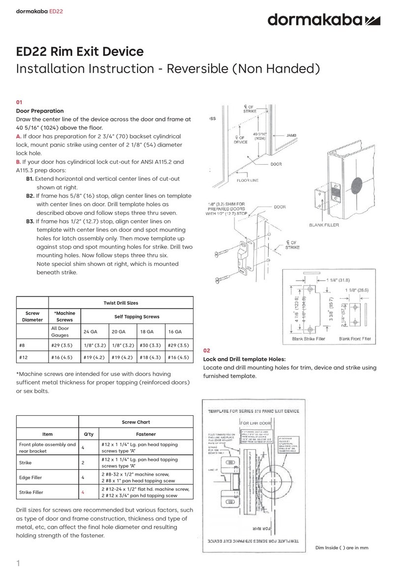
1C - DOOR PREPARATION
TOOLS REQUIRED
The deadbolt is pre-set at 2 ¾" (70mm) backset. Proceed as
illustrated to change to 2 ⅜" (60mm) backset, if required.
Determine which template fits your Saffire LX-I lock installation, either
1.
2 3/8" (60mm) or 2 3/4" (70mm) backset, 4" or 5 1/2" center to center.
Place appropriate template (supplied) onto door and mark holes.
2.
Drill holes as per dimensions on the template. The 1" (25 mm) hole to
3.
be on the center line of door thickness.
Mortise door edge for dead bolt face plate and latch bolt face plate.
4.
Drill 2 1/8" from both sides of the door to prevent unsightly damage.
5.
A = Backset = 2.3/4"(70mm) or 2 3/8" (60mm)
PART LIST & LOCK DIAGRAM
1B - INSTALL STRIKE ON STEEL FRAME
1A - INSTALL STRIKE ON WOOD FRAME
Please continue on next page.
For thicker door please see order guide.
PK3710 - Rev 2
dormakaba Canada inc.
7301 Boul Décarie
Montréal QC H4P 2G7
Canada
1-877-468-3555
www.kabalodging.com
ITEM
NO.
QTY
DESCRIPTION
1 1
FRONT UNIT ZINC HOUSING
2 1
GASKET - FRONT LOCK HOUSING
3 1
TAIL PIECE
4 1
BACK PLATE - INSIDE TRIM
5 1
INSIDE TRIM COVER ASSEMBLY
6 1 DEAD BOLT
7 1
LATCH
8 1
HANDLE ASSEMBLY - OUTSIDE
9 1
STRIKER PLATE AND DUST BOX KIT
10 2
REINFORCING PLATE
11 2
DUST BOX
12 1
STRIKER PLATE
13A
1
SPINDLE ASSEMBLY
13B
1
SPINDLE & RETAINING RING ASSEMBLY
14 1 MESSENGER CABLE (OPTIONAL)
15 1
POWER CABLE
16 1
EXTENSION CABLE (OPTIONAL)
ITEM
NO.
QTY
DESCRIPTION
17 3
PAN HEAD SCREW PHILLIPS, 10-24 x 1-1/4"
18 2
WOOD SCREW PHILLIPS, #8 X 1"
19 4
FLAT HEAD SCREWPHILLIPS, 8-32 X 1/2"
20 2
FLAT HEAD SCREWPHILLIPS, 8-32 X 7/32"
21 2
WOOD SCREW PHILLIPS, #8 X 3"
22 1
PAN HEAD SCREWTORX, 6-32 X 3/16"
23 3
AA BATTERY
24 2
PAN HEAD SCREW PHILLIPS 8-32 X 3/4" OR 1 1/4"
25 2
PAN HEAD SCREW PHILLIPS 6-32 X 1/2"
26 1
REMOVABLE COVER
27 4
COMBO SCREW PHILLIPS #8 X 1"
28 2
COMBO SCREW PHILLIPS #8 X 1"
Outer cam
Groove at 12 o'clock
Inner cam
Left hand (LH)
1- Hold from rotating
2- Rotate to change
from LH to RH
Groove at 6 o'clock
Right hand (RH)
Click in place
"Wire Ring" opening far from slot
2 - Remove screw
1
WARNING
ALIGN STUD AND TAIL PIECE
GENTLY INTO DEAD BOLT
REMOVE TAPE
INSTALL TOP SCREWS
FIRST
CONNECT W1 TO W2
(COMMUNICATION
IF APPLICABLE)
CONNECT V1 TO
V2 (POWER)
ROTATE LEVER CW OR CCW, INSERT A 5/64 OR
2MM TOOL INTO ACCESS HOLE TO HOLD THE
HANDLE DOWN AND CLEAR PASSAGE FOR
SCREW
RUN CABLE THROUGH DOOR
AND UNDER DEADBOLT
RUN CABLES THROUGH INSIDE
TRIM BACKPLATE SLOT
3
3 - Carefully slide the cover off the lever
without scratching it.
ASSEMBLE TAIL PIECE
6.
ASSEMBLE OUTSIDE HOUSING
8.
ADJUST LOCK HANDING ON OUTSIDE HOUSING ASSEMBLY
5.
PK3710 - Rev 2
INSTALL INSIDE TRIM ASSEMBLY
9.
INSTALL 3 TOP SCREWS FIRST TO FRONT LOCK ASSEMBLY THEN
1.
INSTALL IN PLACE LEVER & ROSE ASSEMBLY.
INSTALL 2X BOTTOM SCREW TO LEVER & ROSE ASSEMBLY.
2.
OUTSIDE & INSIDE LOCK ASSEMBLY MUST BE ALIGN VERTICAL.
3.
BEFORE TIGHTENING THE SCREWS VERIFY FUNCTIONALITY BY
4.
EXTRACTING AND RETRACTING THE DEADBOLT. THE DEAD BOLT
SHOULD MOVE SMOOTHLY.
ALL SCREWS SHALL BE THIGHTEN PROPERLY.
5.
TIGHTEN ALL SCREWS.
6.
CONNECT WIRING V1 & V2 AND W1 & W2.
7.
INSTALLED 3X AA BATTERIES
8.
Hold inner cam in place, groove always points to 12 o'clock.
1.
Rotate outer cam counter clockwise until groove points to 6 o'clock
2.
REMOVE INSIDE COVER
7.
1 - Gently snap the door open.
WHILE INSERTING THE LEVER & ROSE
ASSEMBLY IN PLACE, MAKE SURE TO ALIGN
SPINDLE AND SCREW POST WITH THEIR
RESPECTIVE HOLE AND PUSH GENTLY IN.
1
5
2 - 4
3
SPINDLE & RETAINING ASSEMBLY FOR INSIDE TRIM
FOR A LEFT HAND SIDE LOCK, IT SHALL BE POSSIBLE TO ALIGN CAM SLOT
VERTICALY AS SHOWN. IF NOT, INSIDE TRIM CHASSIS AND SLIDER ASSEMBLY
DO NOT HAVE THE PROPER HANDING AND MUST BE REVERSE.
CAM HANDING INDICATOR
FOR A RIGHT HAND SIDE LOCK, IT SHALL BE POSSIBLE TO ALIGN CAM SLOT
VERTICALY AS SHOWN. IF NOT, INSIDE TRIM CHASSIS AND SLIDER ASSEMBLY
DO NOT HAVE THE PROPER HANDING AND MUST BE REVERSE.
CAM HANDING INDICATOR
SPINDLE ASSEMBLY FOR LEVER & ROSE
PK3710 - Rev 2
11. INSTALL INSIDE COVER
10. INSTALL INSIDE TRIM ASSEMBLY
This device complies with Industry Canada license-exempt RSS standard(s). Operation is subject to the following two
conditions: (1) this device may not cause interference, and (2) this device must accept any interference, including
interference that may cause undesired operation of the device.
Le présent appareil est conforme aux CNR d’Industrie Canada applicables aux appareils radio exempts de licence.
L’exploitation est autorisée aux deux conditions suivantes : (1) l’appareil ne doit pas produire de brouillage, et (2)
l’utilisateur de l’appareil doit accepter tout brouillage radioélectrique subi, même si le brouillage est susceptible d’en
compromettre le fonctionnement.”
Note: This equipment has been tested and found to comply with the limits for a Class B digital device, pursuant to part 15
of the FCC Rules. These limits are designed to provide reasonable protection against harmful interference in a residential
installation. This equipment generates, uses and can radiate radio frequency energy and, if not installed and used in
accordance with the instructions, may cause harmful interference to radio communications. However, there is no
guarantee that interference will not occur in a particular installation. If this equipment does cause harmful
interference to radio or television reception, which can be determined by turning the equipment off and on, the user is
encouraged to try to correct the interference by one or more of the following measures:
• Reorient or relocate the receiving antenna.
• Increase the separation between the equipment and receiver.
• Connect the equipment into an outlet on a circuit different from that to which the receiver is connected.
• Consult the dealer or an experienced radio/TV technician for help.”
Changes or modifications not expressly approved by the party responsible for compliance could void the user’s authority
to operate the equipment
This device complies with part 15 of the FCC Rules. Operation is subject to the following two conditions: (1) This device
may not cause harmful
interference, and (2) this device must accept any interference received, including interference that may cause undesired
operation.
IF SPINDLE IS DISCONNECTED FROM LEVER, RE-INSERT SPRING IN LEVER AS FOLLOW:
PUSH THE SPRING LIGHTLY INSIDE LEVER HOLE AND GENTLY TWIST THE SPINDLE AND SPRING ASSEMBLY 2 OR 3 TURNS
COUNTERCLOWISE
THEN PRESS THE SPINDLE ALL THE WAY IN.
AFTER CONNECTING THE CABLES,
ROUTE THE CABLES AROUND THE
CLIPS
SLIDE THE COVER OVER THE LEVER WITHOUT SCRATCHING
1.
THE LEVER.
LIGHTLY SCREW IN THE TWO UPPER SCREWS.
2.
INSTALL THE LOWER SCREW.
3.
TIGHTEN THE UPPER SCREWS IN PLACE.
4.
SNAP IN THE COVER.
5.
ROTATE THE CAM SO THAT THE INNER
SLOT IS HORIZONTAL THEN PLACE THE
INSIDE TRIM INTO POSITION

Other Dormakaba Door Lock manuals

Dormakaba 9000DE Series User manual

Dormakaba

Dormakaba 9000DE Series User manual

Dormakaba AUDITCON 2 Series User manual

Dormakaba

Dormakaba AUDITCON 2 Series User manual

Dormakaba E7900 Series User manual

Dormakaba

Dormakaba E7900 Series User manual

Dormakaba ED22 User manual

Dormakaba

Dormakaba ED22 User manual

Dormakaba ED50LE User manual

Dormakaba

Dormakaba ED50LE User manual

Dormakaba RD10 User manual

Dormakaba

Dormakaba RD10 User manual

Dormakaba 143 Series User manual

Dormakaba

Dormakaba 143 Series User manual

Dormakaba 100 User manual

Dormakaba

Dormakaba 100 User manual

Dormakaba c-lever pro User manual

Dormakaba

Dormakaba c-lever pro User manual

Dormakaba Rose User manual

Dormakaba

Dormakaba Rose User manual

Dormakaba HSW EASY SAFE User manual

Dormakaba

Dormakaba HSW EASY SAFE User manual

Dormakaba ML530 User manual

Dormakaba

Dormakaba ML530 User manual

Dormakaba Saffire LX User manual

Dormakaba

Dormakaba Saffire LX User manual

Dormakaba STUDIO Rondo Glass/Glass User manual

Dormakaba

Dormakaba STUDIO Rondo Glass/Glass User manual

Dormakaba 79 Series User manual

Dormakaba

Dormakaba 79 Series User manual

Dormakaba Confidant RFID User manual

Dormakaba

Dormakaba Confidant RFID User manual

Dormakaba SVA 2000 User manual

Dormakaba

Dormakaba SVA 2000 User manual

Dormakaba SVA 2000 User manual

Dormakaba

Dormakaba SVA 2000 User manual

Dormakaba Saffire EVO User manual

Dormakaba

Dormakaba Saffire EVO User manual

Dormakaba YG80 User manual

Dormakaba

Dormakaba YG80 User manual

Dormakaba 8300 Series User manual

Dormakaba

Dormakaba 8300 Series User manual

Dormakaba Saffire LX User manual

Dormakaba

Dormakaba Saffire LX User manual

Dormakaba BEST Switch Core User manual

Dormakaba

Dormakaba BEST Switch Core User manual

Dormakaba LA GARD 700 Series User manual

Dormakaba

Dormakaba LA GARD 700 Series User manual

Popular Door Lock manuals by other brands

Assa Abloy Corbin Russwin Access 600 TCRNE1 Series installation instructions

Assa Abloy

Assa Abloy Corbin Russwin Access 600 TCRNE1 Series installation instructions

Salto XS4 Mini installation guide

Salto

Salto XS4 Mini installation guide

Embassy HOME EL1 user manual

Embassy

Embassy HOME EL1 user manual

SECO-LARM SD-997A-GBQ installation manual

SECO-LARM

SECO-LARM SD-997A-GBQ installation manual

BDS TML25 Installation

BDS

BDS TML25 Installation

Onward 9016H installation instructions

Onward

Onward 9016H installation instructions

Assa Abloy Yale Real Living Assure Lock YRD226 Installation and programming instructions

Assa Abloy

Assa Abloy Yale Real Living Assure Lock YRD226 Installation and programming instructions

Kwikset Burbank Quick installation guide

Kwikset

Kwikset Burbank Quick installation guide

Beninca E.LOCK installation manual

Beninca

Beninca E.LOCK installation manual

Trine 3000 Series manual

Trine

Trine 3000 Series manual

Paxton Ins-30169 Net2 PaxLock Mifare instruction manual

Paxton

Paxton Ins-30169 Net2 PaxLock Mifare instruction manual

Von Duprin CX33A installation instructions

Von Duprin

Von Duprin CX33A installation instructions

Signature Hardware Traeger 946282-DU manual

Signature Hardware

Signature Hardware Traeger 946282-DU manual

Salto XS4 Mini installation guide

Salto

Salto XS4 Mini installation guide

Signature Hardware BULLOCK 915876-DU Installation

Signature Hardware

Signature Hardware BULLOCK 915876-DU Installation

Connective Touch FLEXI User guide lines

Connective Touch

Connective Touch FLEXI User guide lines

Extel WECA 109058 Installation and operation manual

Extel

Extel WECA 109058 Installation and operation manual

Dorex 9500 quick start guide

Dorex

Dorex 9500 quick start guide

manuals.online logo
manuals.online logoBrands
  • About & Mission
  • Contact us
  • Privacy Policy
  • Terms and Conditions

Copyright 2025 Manuals.Online. All Rights Reserved.