9
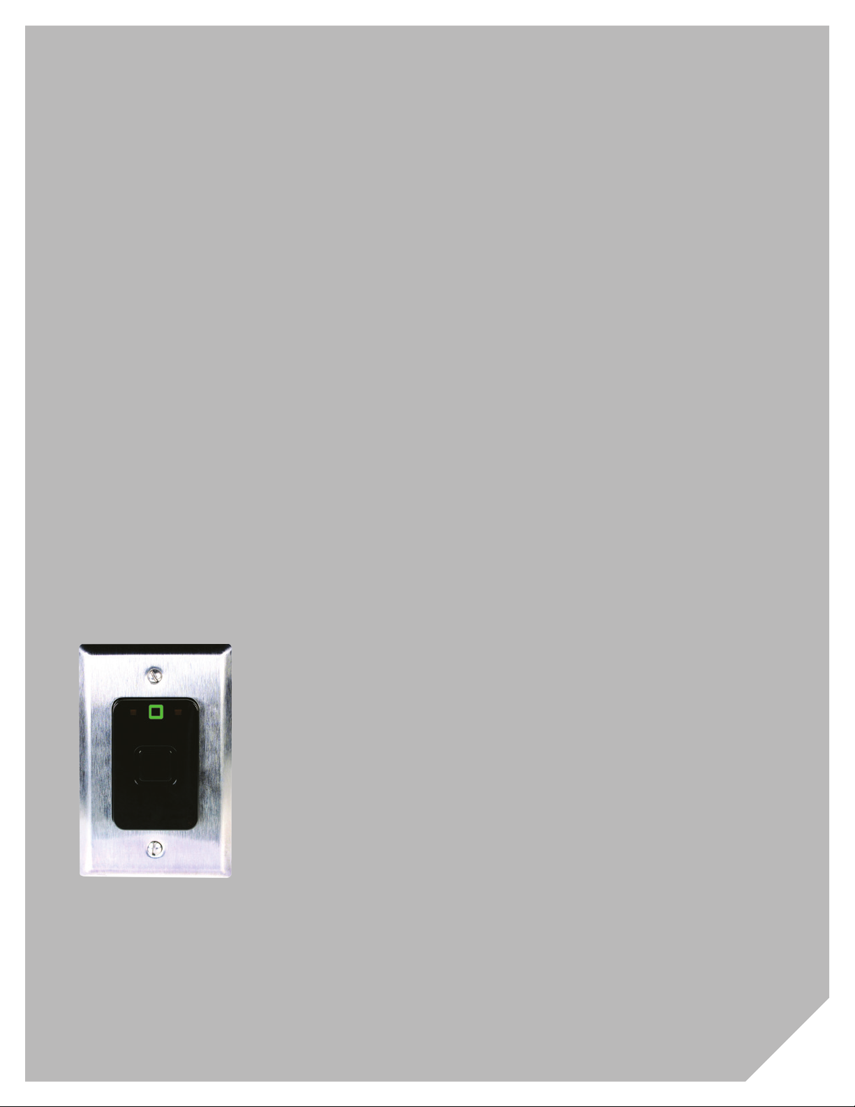
Saflok SRTM Series RFID Concierge Installation Guide - PK3673_T_07_16
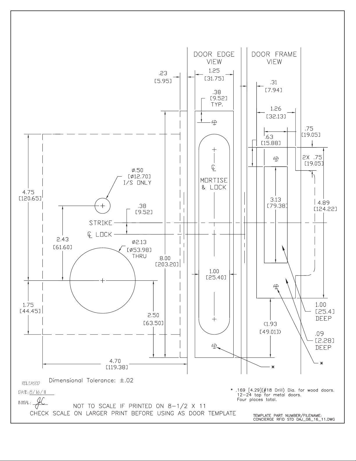
1. Prepare door mortise pocket and wire routing tunnel as previously described. (Pg. 3-5)
2. Install power transfer hardware as outlined by manufacturer instructions.
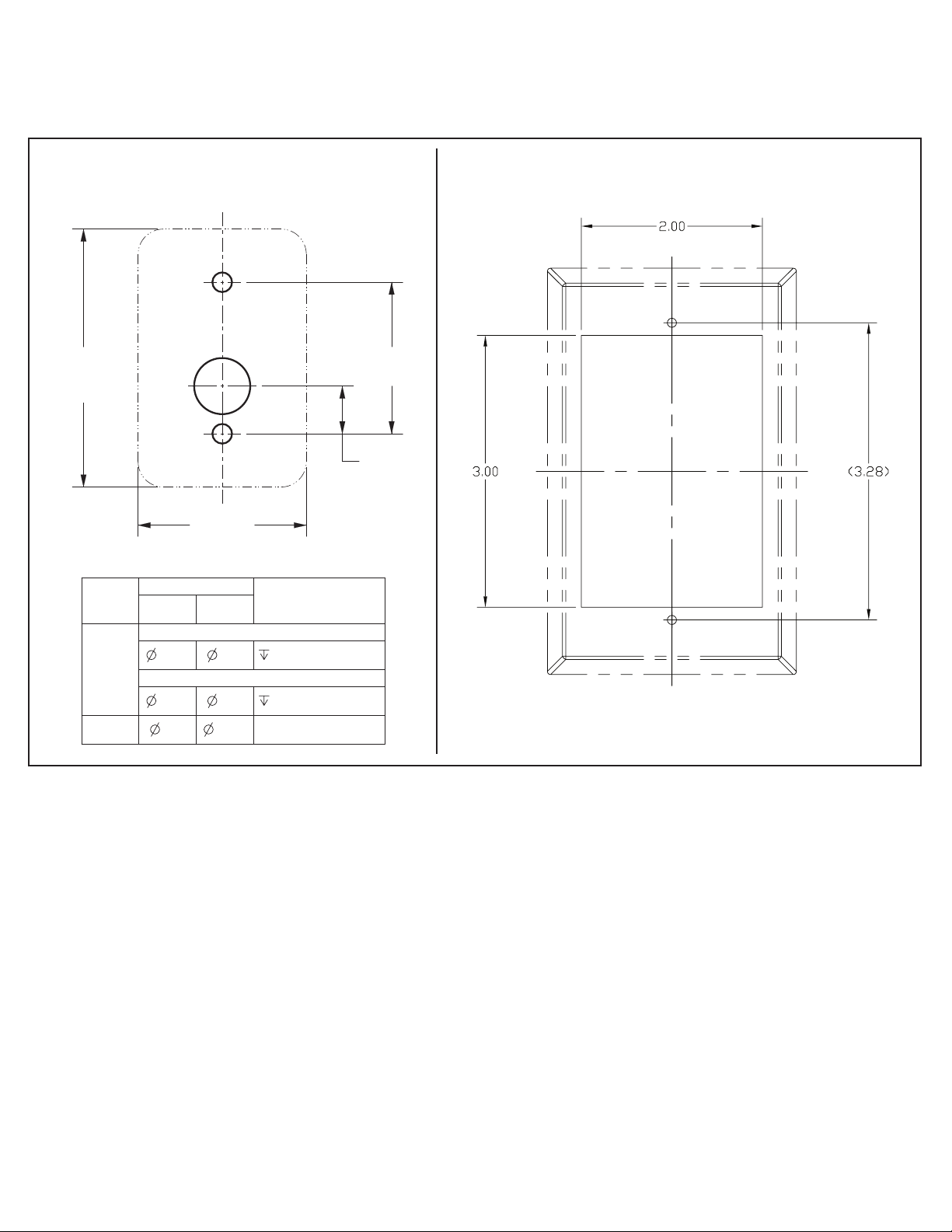
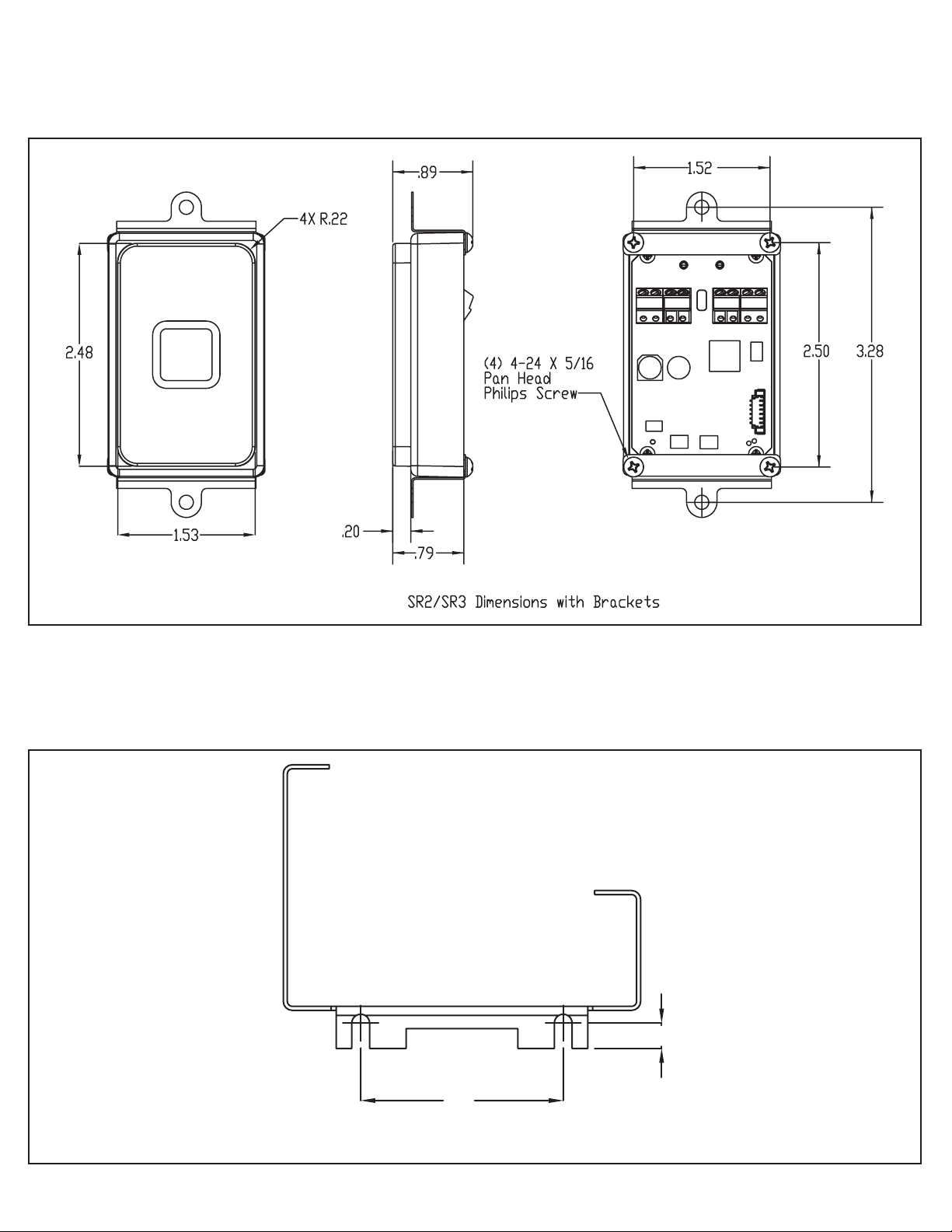
3. Install any supplied mounting brackets, controller boxes, and assemblies as desired using the installation mount-
ing templates/dimension guidelines outlined previously.
4. Ensure you have the proper low voltage power (12 to 24 AC or DC) in place at the final controller location.
5. Ensure controller bracket is properly grounded (See SR Controller Internal Parts drawing Pg. 11) by using the
supplied ground wire.
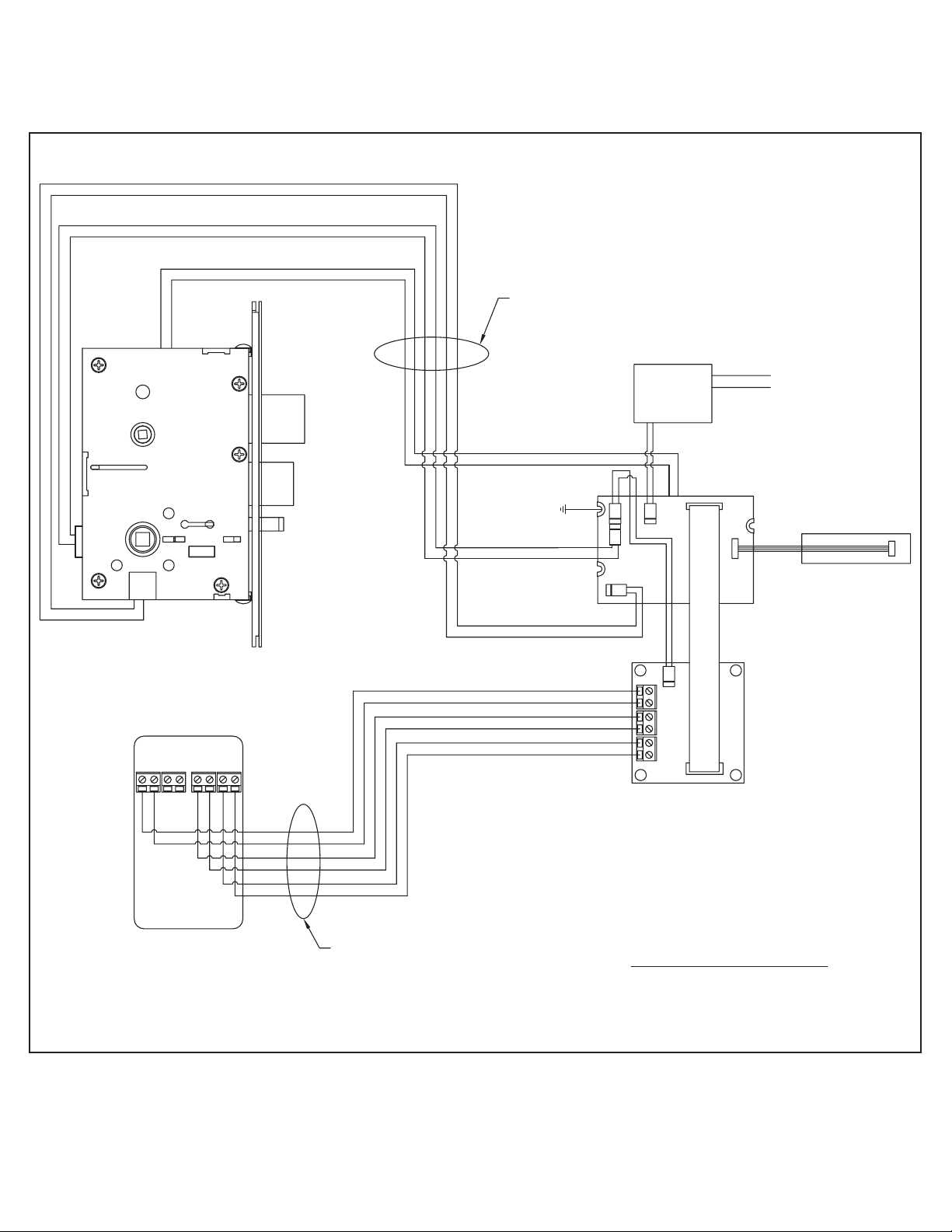
6. Use the schematic provided to run the appropriate wires from the SR reader to the controller using 3 twisted
pair x 22 AWG CMP cable (Belden 6542FE or equivalent). Note - each connection on the reader and controller
interface board are labeled. Do not exceed 15 meters.
7. Prepare the mortise (see Mortise Preparation illustration Pg. 11) for wiring by removing the Motor and DAJ
connectors. Strip and label each wire appropriately after removing the connectors.
8. Use the schematic provided on Pg.10 to run the appropriate wires (3 twisted pair x 22 AWG CMP cable, Belden
6542FE, or equivalent) from the controller, through the power transfer hardware, and through the door to the
mortise pocket. Do not exceed 15 meters.
9. Connect the wires from the controller to the mortise using the supplied wire nuts.
10. Verify all wiring is correct.
11. Install mortise into door pocket.
12. Connect appropriate power to controller box.
13. Test assembly using a construction key.
14. Program the lock by using the property's hand held programmer (see programming annex Pg. 12).
15. Test assembly using a property key.
16. Secure the faceplate to the controller box (if applicable) with the four #6-32 x 1” screws provided.
17. Secure reader assembly
SR1 Surface Mount: Hang the reader housing on the back plate clip, swing down into position, and fasten with
the #8-32 screw (provided) through hole in bottom of case.
SR2 Flush Mount Reader: Secure the faceplate to the reader box with the two #6-32 x 1” provided.
SR3 as required by integrator
18. After all hardware is securely in place retest lock.
SR Concierge Kit Installation Instructions