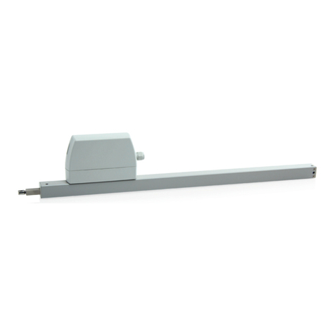
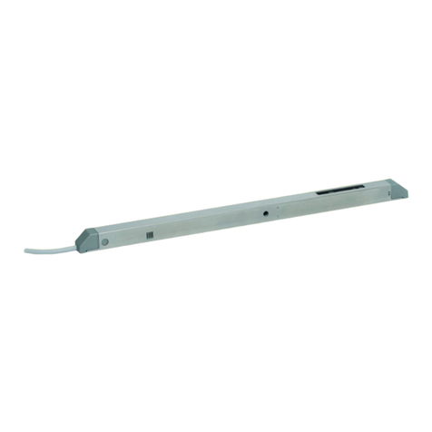
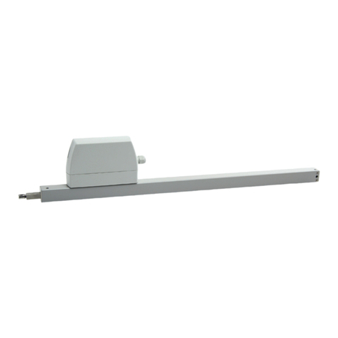
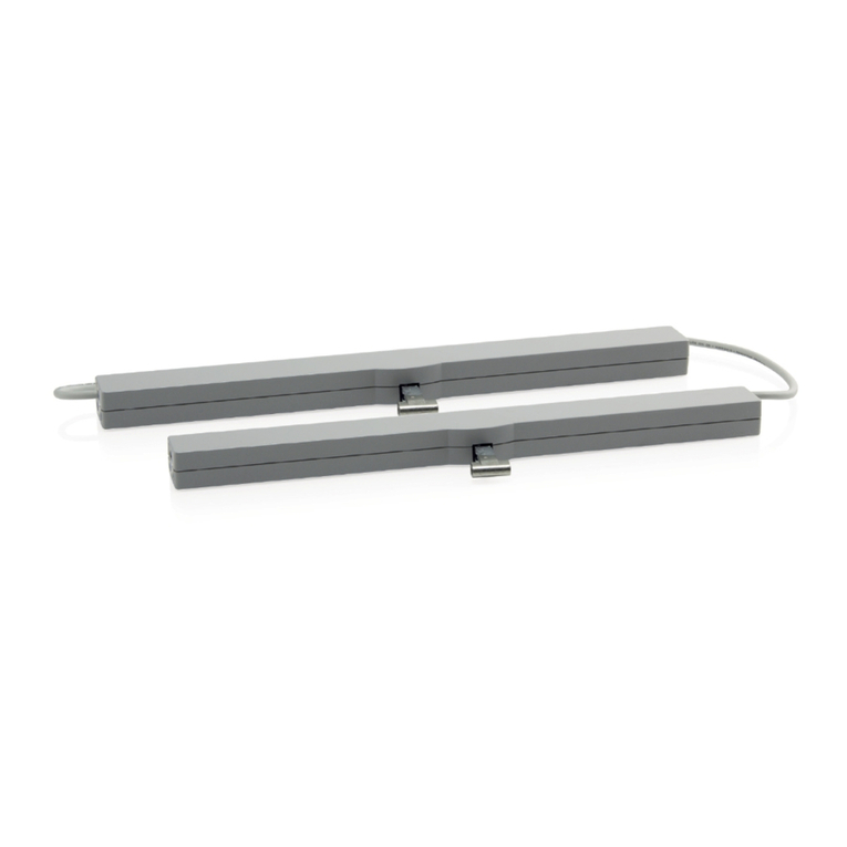
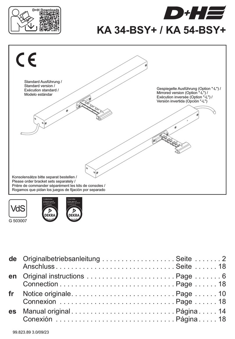
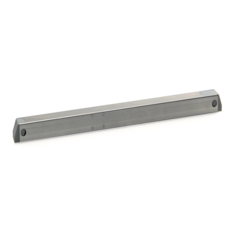
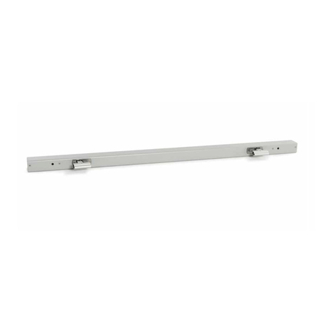
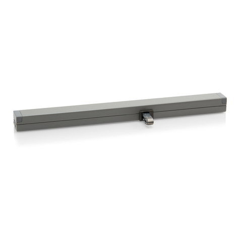
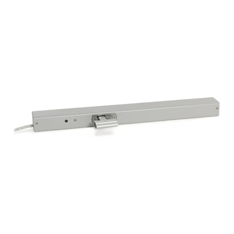
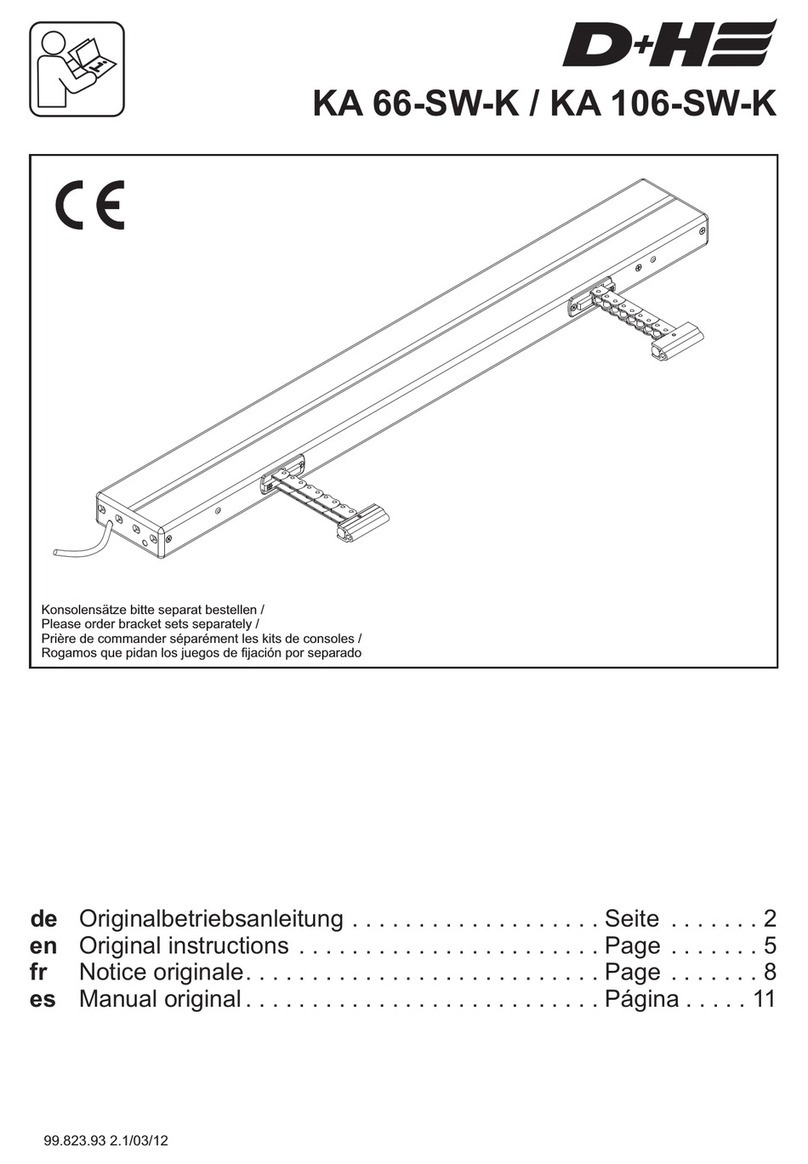
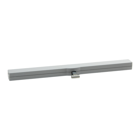
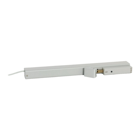
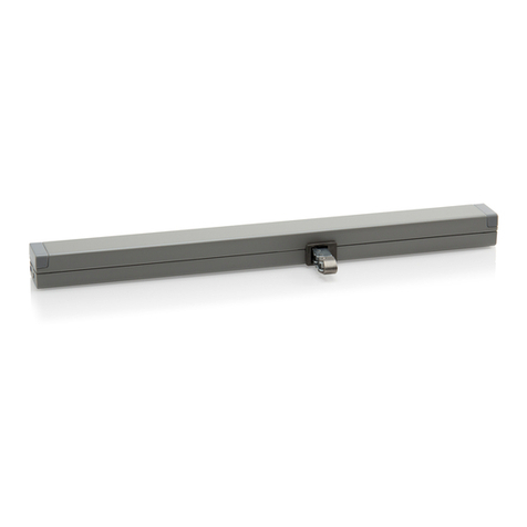
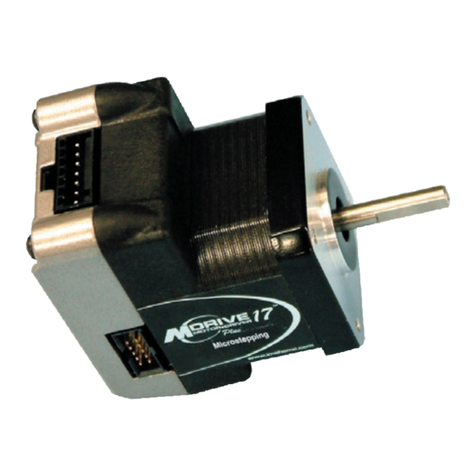
D+H DYER VCD 204-K-TMS+ Set User manual

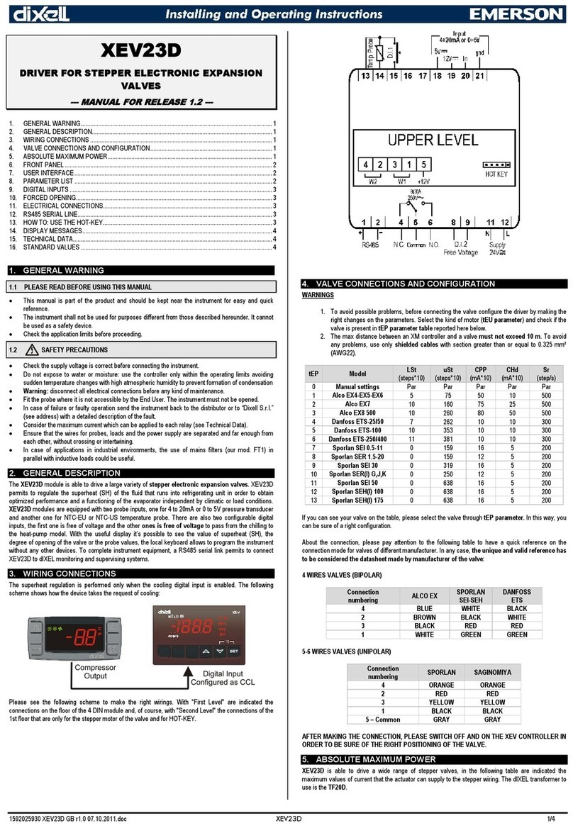
VCD 204-K-TMS+ Set instructions
Please order bracket sets separately
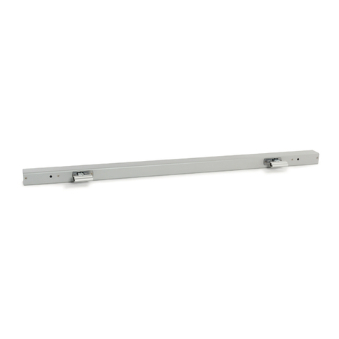
VCD 204-Z-TMS+ A
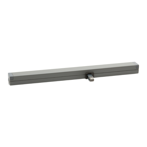
VCD 204-K-TMS+ B
With built-in power supply
230 VAC
50 Hz

99.831.12 1.1/02/16
4/16 Deutsch
1x VCD 204-K-TMS+ B with built-in power supply
1x VCD 204-Z-TMS+ A
1x 2,5 m PVC cable
1x 1,2 m patch cable
Dependent on the type of window, different bracket
sets are available separately.
Extent of supply
VCD 204-K-TMS+ Set VCD 204-K-TMS+ Set
Safety notes
Operating voltage 230 V AC!
Risk of injury from electric shock!
Do not reverse L+N! Connect PE!
- Connection must be carried out by a certified
electrical technician
- Danger of crushing hands and fingers!
- Keep people away from the operating area of the drive
- Keep children away from the control
- Use only in dry rooms
- Suitable for indoor mounting only.
Use rain detector in locations if there is a risk of rain
- Use unmodified original D+H parts only
- Observe the bracket-set mounting instructions
Observe enclosed red safety note!
Intended use
- Chain drive set for electric opening and closing of
windows and flaps in the facade and roof area
- Useable for daily natural ventilation
- Operating voltage 230 V AC
- Only for inside mounting
- These drives are not compatible with other
VCD 204 drives!
Performance features
- micro processor controlled electronics
- Stroke programming with magnet
- Low running noises
- Connection via plug connector
- Symmetrical chain outlet
- Tandem-safety function (TMS+) for operation of
both drives on one sash
Up to two drives can be used in tandem. This function
connects the cut-offs of the two drives in such a way
that if one drive is cut off due to overload, the other
drive will similarly be cut off.
During the learning phase, the activated stroke is
transferred to the tandem drive via the TMS+ function.
TMS+ function
Hubbegrenzung mit Magnet
Antriebe einfahren.
1Antriebe so lange in AUF-
Richtung fahren lassen bis
gewünschter Hub erreicht wurde.
Sollte ein falscher Hub eingestellt
oder versehentlich die Fahrt
unterbrochen worden sein
oder die Antriebe wieder auf
maximale Hublänge gebracht
werden, muss wieder mit Punkt 1
begonnen werden.
3
An den Antrieben muss in
ZU-Richtung weiter Spannung
anliegen.
Magnet anAntrieb (...-B) halten (ca.
2 sek.), bis nach einem pulsier-
enden Ton ein Dauerton kommt
> Antriebe sind imAnlernmodus.
Der Magnet kann entfernt werden.
Die Spannung muss nicht mehr
am Antrieb anliegen.
ca.100 mm
Anlernmodus
ca. 2 sek.
2
Zur Hubeinstellung müssen beide Antriebe elektrisch verbunden sein.
Es muss aber nur ein Antrieb mit dem Magnet in den Hubanlernmodus versetzt werden.
Antriebe mechanisch spannungsfrei montieren.
Hierdurch wird eine gleichmäßigere Lastverteilung
auf alle Antriebe gewährleistet.
Montagehinweise
VCD 204-K-TMS-B
24 VDC
230 VAC
STOP
Elektrogeräte, Zubehör, Batterien und Verpackungen
sollen einer umweltgerechten Wiederverwertung
zugeführt werden. Werfen Sie Elektrogeräte und
Batterien nicht inden Hausmüll!
Nur für EU-Länder:
Gemäß der Europäischen Richtlinie 2012/19/EU
über Elektro- und Elektronik-Altgeräte und ihrer
Umsetzung in nationales Recht müssen nicht mehr
gebrauchsfähige Elektrogeräte getrennt gesammelt
und einer umweltgerechten Wiederverwertung
zugeführt werden.
Entsorgung
Maintenance and cleaning
Maintenance work is only allowed when the device is in
a de-energized condition! Inspection and maintenance
has to be carried out according to D+H maintenance
notes. Only original D+H spare parts may be used.
Repair is to be carried out exclusively by D+H.
Wipe away debris or contamination with a dry, soft
cloth.
Do not use cleaning agents or solvents.
Guarantee
You will get 2 years guarantee for all D+H products
from date of verified handing over of the system up to
maximal 3 years after date of delivery, when
mounting and starting has been carried out by an
authorized D+H-distributor.
D+H guarantee is expired, with connection of D+H
components with external systems or with mixing of
D+H products with parts of other manufacturers.
WARNING
Read all safety warnings, instructions, illustrations
and specifications provided with this product.
Failure to follow all instructions listed below may
result in electric shock, fire and/or serious injury.
Save all warnings and instructions for future
reference.
Declaration of Conformity
We declare under our sole responsibility that the
product described under “Technical Data” is in
conformity with the following directives:
2014/30/EU, 2014/35/EU
Technical file at:
D+H Mechatronic AG, D-22949 Ammersbek
Dirk Dingfelder Maik Schmees
Member of the Board Authorized signatory, Technical Director
24.02.2016

Mount the drives mechanical stress-free.
With that, a better load distribution is ensured on all
the drives.
Mounting informations
English
99.831.12 1.1/02/16 7/16
VCD 204 -K VCD 204 -K
Closing edge protection
In the "CLOSE" direction the drive set has an active
protection for the main closing edge. If there is an
overload in the closing ranges 3 and 2, the drives run
"OPEN" for 20 seconds, then "CLOSE" again. If
closing is not possible after three attempts, the
drives remain in this position.
In addition, the drives are equipped with passive
protection. The closing speed in closing range 2 and
1 is reduced to 5 mm/s.
Significantly greater forces can be
exerted at the secondary closing edges.
Danger of crushing hands and fingers!
Main closing edge
Secondary closing edge
Voltage must continue to
be applied to the drives when
moving in the “CLOSE”
direction. Hold the magnet next
to the drive (...-B) as shown in the
diagramme (2 sec.) until you hear
a pulsating ton > The drives are
now in learning mode. The magnet
can now be removed and the drive
no longer has to be under voltage.
Stroke limiting with magnets
Close drives.
1Allow the drives to run
“OPEN” until you reach the
required stroke.
If the stroke is set incorrectly,
the procedure is accidentally
interrupted or the drives
continues to the full stroke
length, please return to point 1
and start again.
3
appr.100 mm
learning mode
appr. 2 sec.
2
Both drives must be electrically connected in order to set the stroke.
Only one drive needs to be switched to the stroke learning mode with the magnet.
VCD 204-K-TMS-B
24 VDC
230 VAC
STOP
Electrical devices, accessories, batteries and packa-
ging should be sorted for environmental-friendly
recycling. Do not dispose electrical devices and
batteries into household waste!
Only for EC countries:
According the European Guideline 2012/19/EU for
waste electrical and electronic equipment and its
implementation into national right, electrcal devices
that are no longer usable must be collected separa-
tely and disposed of in an environmentally correct
manner.
Disposal
Type VCD 204 -K-TMS+ Set
Power supply 230 V AC / +10...-15 % / 50 ... 60 Hz
Power consumption 22 W / 30 VA
Nominal force 2x 200 N
Nominal locking force approx. 2x 2000 N (Excluding bracket)
Service life >20 000 double strokes
Duty cycle 30 % (With cycle time 10 minutes)
Housing Zinc-diecasting, powdercoated
Ingress protection IP 30
Temp. range 0 ... +60 °C
Emission sound pressure level LpA ≤ 70 dB(A)
Nominal stroke length* See type plate
Additional functions Closing edge protection activated (3 stroke repeatings),
Locking relief activted
* Adjustable with magnet
All forces + approx. 20 % switch-off reserve (temporary)
Closure Ranges
~6 mm/s
150 N
(Safety cut-off force)
5 mm/s
150 N
77 mm
~6 mm/s
200 N
23 mm
Running speed and forces
Technical data

Mount the drives mechanical stress-free.
With that, a better load distribution is ensured on all
the drives.
Mounting informations
English 99.831.12 1.1/02/16
6/16 VCD 204 -K VCD 204 -K
Closing edge protection
In the "CLOSE" direction the drive set has an active
protection for the main closing edge. If there is an
overload in the closing ranges 3 and 2, the drives run
"OPEN" for 20 seconds, then "CLOSE" again. If
closing is not possible after three attempts, the
drives remain in this position.
In addition, the drives are equipped with passive
protection. The closing speed in closing range 2 and
1 is reduced to 5 mm/s.
Significantly greater forces can be
exerted at the secondary closing edges.
Danger of crushing hands and fingers!
Main closing edge
Secondary closing edge
Voltage must continue to
be applied to the drives when
moving in the “CLOSE”
direction. Hold the magnet next
to the drive (...-B) as shown in the
diagramme (2 sec.) until you hear
a pulsating ton > The drives are
now in learning mode. The magnet
can now be removed and the drive
no longer has to be under voltage.
Stroke limiting with magnets
Close drives.
1Allow the drives to run
“OPEN” until you reach the
required stroke.
If the stroke is set incorrectly,
the procedure is accidentally
interrupted or the drives
continues to the full stroke
length, please return to point 1
and start again.
3
appr.100 mm
learning mode
appr. 2 sec.
2
Both drives must be electrically connected in order to set the stroke.
Only one drive needs to be switched to the stroke learning mode with the magnet.
VCD 204-K-TMS-B
24 VDC
230 VAC
STOP
Electrical devices, accessories, batteries and packa-
ging should be sorted for environmental-friendly
recycling. Do not dispose electrical devices and
batteries into household waste!
Only for EC countries:
According the European Guideline 2012/19/EU for
waste electrical and electronic equipment and its
implementation into national right, electrcal devices
that are no longer usable must be collected separa-
tely and disposed of in an environmentally correct
manner.
Disposal
Type VCD 204 -K-TMS+ Set
Power supply 230 V AC / +10...-15 % / 50 ... 60 Hz
Power consumption 22 W / 30 VA
Nominal force 2x 200 N
Nominal locking force approx. 2x 2000 N (Excluding bracket)
Service life >20 000 double strokes
Duty cycle 30 % (With cycle time 10 minutes)
Housing Zinc-diecasting, powdercoated
Ingress protection IP 30
Temp. range 0 ... +60 °C
Emission sound pressure level LpA ≤ 70 dB(A)
Nominal stroke length* See type plate
Additional functions Closing edgeprotectionactivated (3 strokerepeatings),
Locking relief activted
* Adjustable with magnet
All forces + approx. 20 % switch-off reserve (temporary)
Closure Ranges
~6 mm/s
150 N
(Safety cut-off force)
5 mm/s
150 N
77 mm
~6 mm/s
200 N
23 mm
Running speed and forces
Technical data

WH (+24 V)
YE (TMS+)
BN (–)
GN (SKS)
GY (SKS)
PK (n.c.)
WH (+24 V)
YE (TMS+)
BN (–)
GN (SGI)
GY (SGI)
PK (n.c.)
WH (+24 V)
YE (TMS+)
BN (–)
GN (n.c.)
WH (+24 V)
YE (TMS+)
BN (–)
GN (n.c.)
Standard
Option
-SA-SZ
Option
-SGI
Option
-SKS
L+N nicht vertauschen! PE anschließen! /
Do not reverse L+N! Connect PE! /
Ne pas intervertir L+N ! Raccorder PE ! /
¡No confundir L+N! ¡Conectar la puesta a tierra!
(BN)
(BK)
(BU)
(GN/YE)
L
N
PE
230 VAC
50 Hz
Anschluss / Connection / Connexion / Conexión
(WH)
(BN)
(YE)
+24 V
–
TMS+
Verbindungskabel /
Patch cable /
Câble de connexion /
Cable de conexión
(BN) braun / brown / brun / marrón
(BK) schwarz / black / noir / negro
(BU) blau / blue / bleu / azul
(YE) gelb / yellow / jaune / amarillo
(GN) grün / green / vert / verde
(WH) weiss / white / blanc / blanco
(PK) rosa / pink / rose / rosa
(GR) grau / grey / gris / gris
L L N
(WH)
(BN)
(YE)
230 VAC
24 VDC
+24 V
–
TMS+
Pin Assigment
DE / EN / FR / ES
99.831.12 1.1/02/16 15/16
VCD 204 -K VCD 204 -K
VCD 204-K-TMS+ B VCD 204-Z-TMS+ A
230 VAC 24 VDC
BN (L )
BK (L )
YE/GN ( )
BU (N)
s
r
WH (+24 V)
YE (TMS+)
BN (–)
GN
GY
PK
BN (L )
BK (L )
YE/GN ( )
BU (N)
BN (L )
BK (L )
YE/GN ( )
BU (N)
BN (L )
BK (L )
YE/GN ( )
BU (N)
max.
50 V /
0,5 A
VCD 204-K-TMS+ B VCD 204-Z-TMS+ A
230 VAC 24 VDC
WH (+24 V)
YE (TMS+)
BN (–)
GN (n.c.)
WH (+24 V)
YE (TMS+)
BN (–)
GN (n.c.)
WH (+24 V)
YE (TMS+)
BN (–)
GN (n.c.)
Optional signals
mains supply
Junction box

WH (+24 V)
YE (TMS+)
BN (–)
GN (SKS)
GY (SKS)
PK (n.c.)
WH (+24 V)
YE (TMS+)
BN (–)
GN (SGI)
GY (SGI)
PK (n.c.)
WH (+24 V)
YE (TMS+)
BN (–)
GN (n.c.)
WH (+24 V)
YE (TMS+)
BN (–)
GN (n.c.)
Standard /
Estándar
Option /
Opción -SA-SZ
Option /
Opción-SGI
Option /
Opción -SKS
Do not reverse L+N! Connect PE!
(BN)
(BK)
(BU)
(GN/YE)
L
N
PE
230 VAC
50 Hz
Connection
(WH)
(BN)
(YE)
+24 V
–
TMS+
Patch cable
(BN) brown
(BK) black
(BU) blue
(YE) yellow
(GN) green
(WH) white
(PK) pink
(GR) grey
L L N
(WH)
(BN)
(YE)
230 VAC
24 VDC
+24 V
–
TMS+
AderbelegungStecker / Pin Assigment / Brochagedes fiches/ Asignacióndecables
DE / EN / FR / ES 99.831.12 1.1/02/16
14/16 VCD 204 -K VCD 204 -K
VCD 204-K-TMS+ B VCD 204-Z-TMS+ A
230 VAC 24 VDC
BN (L )
BK (L )
YE/GN ( )
BU (N)
s
r
WH (+24 V)
YE (TMS+)
BN (–)
GN
GY
PK
BN (L )
BK (L )
YE/GN ( )
BU (N)
BN (L )
BK (L )
YE/GN ( )
BU (N)
BN (L )
BK (L )
YE/GN ( )
BU (N)
max.
50 V /
0,5 A
VCD 204-K-TMS+ B VCD 204-Z-TMS+ A
230 VAC 24 VDC
WH (+24 V)
YE (TMS+)
BN (–)
GN (n.c.)
WH (+24 V)
YE (TMS+)
BN (–)
GN (n.c.)
WH (+24 V)
YE (TMS+)
BN (–)
GN (n.c.)
Optionale Meldungen / Optional signals / Signals optional / Señales opcional
Netzanschluss /
mains supply /
Raccord secteur /
Conexión a la red
Abzweigdose /
Junction box /
Boîte de dérivation /
Caja de conexión

30 mm
41,2 mm
480 mm
47 mm
240 mm 240 mm
Dimensions
Dyer Environmental Controls Ltd
Unit 10 Lawnhurst Trading Estate, Cheadle Heath,
Stockport SK3 0SD
Tel: +44 (0)161 491 4840
E-Mail: [email protected]
www.dyerenvironmental.co.uk
This manual suits for next models
7
Table of contents
Other D+H DC Drive manuals

D+H
D+H ZA 105-K User manual

D+H
D+H ZA35-BSY+(-HS) User manual

D+H
D+H KA 66-TW User manual

D+H
D+H VCD 204-K-TMS-B User manual

D+H
D+H CDC-TW-0502-0350-1-ACB User manual

D+H
D+H VCD Series User manual

D+H
D+H ZA 35-K-BSY+ User manual

D+H
D+H KA 34-BSY+ User manual

D+H
D+H CDC 200/350 -SBD User manual

D+H
D+H KA 34-BSY+ User manual