99.823.67 2.6/03/16
CDC 200/350(-SBD)-BSY+
6/20 English
Intended use
- Chain drive for electric opening and closing of
windows and flaps in the facade and roof area
- Operating voltage 24 V DC
- Usable for smoke extraction, D+H Euro-SHEV in
accordance with DIN EN 12101-2 as well as daily
ventilation
- Suitable for indoor mounting only
Safety notes
Safety extra low voltage 24 V DC!
Do not connect directly to the mains supply!
- Connection must be carried out by a certified
electrical technician
- Danger of crushing hands and fingers!
- Keep people away from the operating area of the
drive
- Keep children away from the control
- Observe pressure load diagram of the chain
- Use only in dry rooms
- Suitable for indoor mounting only. Use rain
detector in locations if there is a risk of rain
- Use unmodified original D+H parts only
Observe enclosed red safety note!
Features
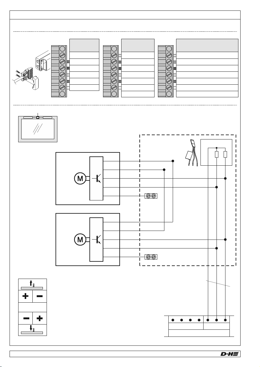
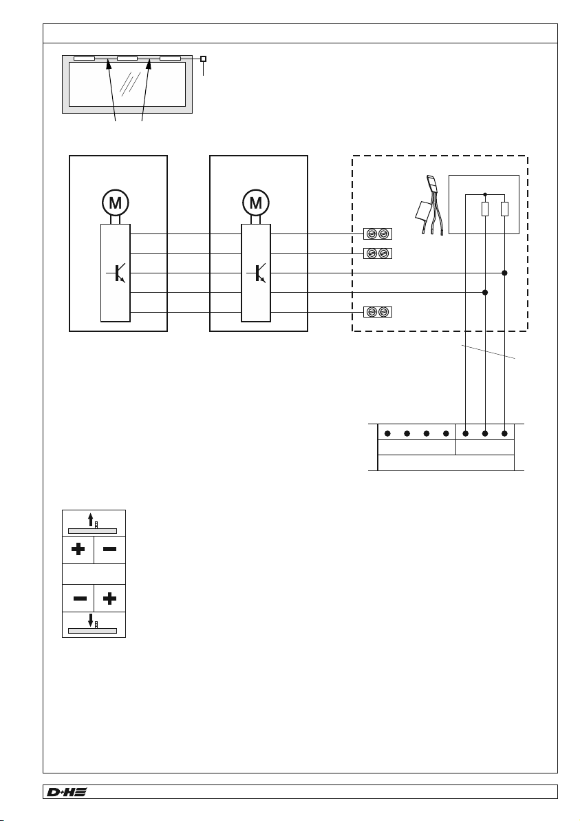
- Microprocessor-controlled synchronous
electronics BSY+ for safe and precise
synchronous running of up to 8 drives
- Individually programmable via software SCS
- Especially quiet motor running in ventilation mode
- Protection system for the main closing edge
- Rated voltage and Bus-signals loopable for max.
3 drives
- Power supply from left or right
- Relief of pressure on window gasket after closing
- Direct connection of an additional closing edge
pinch protection ledge to drive is possible
(Option -SKS)
CDC 200/350 (-SBD)-BSY+ 7/20
99.823.67 2.6/03/16 English
Type CDC 200/350 -BSY+ CDC 200/350 -SBD -BSY+
Rated voltage 24 V DC, ±15 %, 0,6 A 24 V DC, ±15 %, 0,5 A
Chain type Standard chain Side bow chain
Nominal pressure 200 N 150 N
Nominal locking force approx. 1500 N
Service life >20.000 double strokes
Housing Aluminium die casting
Protective system IP 50
Temp.range -5 ... +75 °C
Fire stability 30 min / 300 °C
Emission sound pressure level LpA ≤ 70 dB(A)
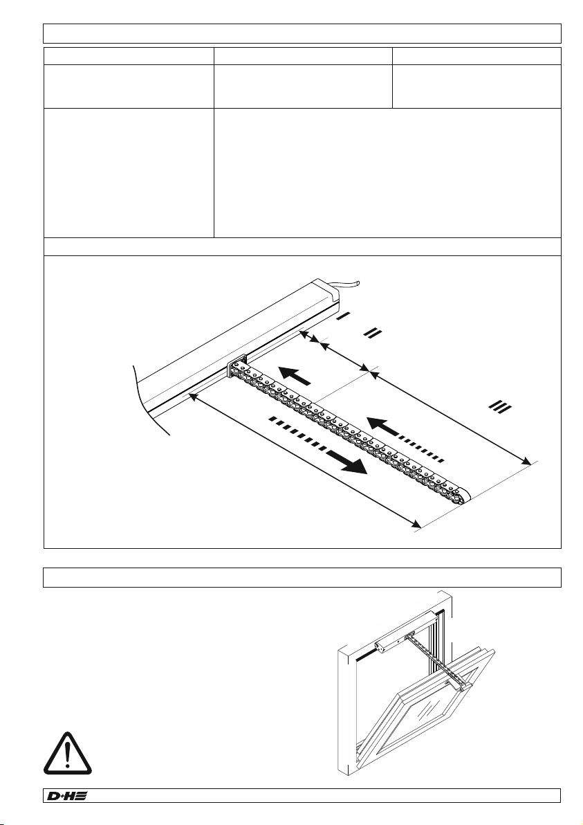
Stroke lenght * max. 350 mm
Additional functions * Closing edge protection = activated (3 repetitions of stroke)
Locking relief = activated (retraction lift max. 0,2 mm)
* Programmable with software SCS
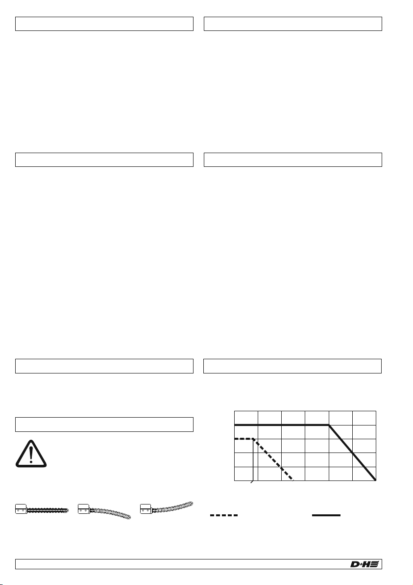
Running speed and forces
Closing Range
77 mm
5 mm/s
150 N
5 mm/s
150 N
23
CDC 200/350-BSY+:200 N, 6,7 mm/s
CDC 200/350-SBD-BSY+: 150 N, 6,7 mm/s
All forces + approx. 20 % switch-off reserve (temporary)
Main closing edge
Beside closing edge
Beside
closing edge
Closing edge protection
In the "CLOSE" direction the drive has an active
protection for the main closing edge. If there is an
overload in the closing ranges 3 and 2, the drive runs
"OPEN" for 10 seconds, then "CLOSE" again. If
closing is not possible after three attempts, the drive
remains in this position.
In addition, the drive is equipped with passive
protection. The closing speed in closing range 2 and
1 is reduced to 5 mm/s.
Significantly greater forces can be
exerted at the secondary closing
edges. Danger of crushing hands and
fingers!
Scope of supply
Drive unit with 2.5 m silicone cable. Depending on
the type of window, different bracket sets are
available separately.
-SBD
Standard chain
-SBU
Side bow chain Side bow chain
Chain type
The mounting instructions for the bracket
set must be observed before mounting.
Always observe and comply with the
information in the mounting instructions.
Attention with side bow chains SBD and SBU
Observe maximum pressure load of the chain!
Maximum pressure load of chain is not automatically
identical with maximum pressure force of the drive!
Pressure load diagram
Pressure load (N)
-SBD / -SBU Standard
100
200
300
400
500
600
50
100
150
200
250
250
80
Stroke (mm)
WARNING
Read all safety warnings, instructions, illustrations
and specifications provided with this product.
Failure to follow all instructions listed below may
result in electric shock, fire and/or serious injury.
Save all warnings and instructions for future
reference.
Technical Data


 User manual")


 User manual")


