Dräger Incubator 8000 IC Parts list manual

6141.22X Incubator 8000 IC/SC/NC Function Description 09.99 Page 1 of 49
Function Description Incubator 8000 IC / SC / NC
Table of contents:
1General.............................................................................................................................3
1.1Description of the Incubator 8000 IC / SC / NC............................................................3
1.2Safety Features.............................................................................................................5
1.3Alarms...........................................................................................................................5
1.3.1Alarm for set value deviationsand water shortage 5
1.3.2Sensor alarmsand fan failure alarm 6
1.3.3Module faults6
1.3.4Total shutdown7
2Functional description of Incubator 8000 IC / SC / NC.....................................................7
2.1Description of component block diagram......................................................................7
2.1.1Component block diagram 8000 IC7
2.1.2Component block diagram 8000 SC / NC 10
2.1.3Fresh air intake and O2 supply13
2.1.4Heating unit13
2.1.5Electronicsmodule14
2.1.6Climate sensor housing (Inc. 8000 IC) 15
2.1.7Air temperature sensor (Inc. 8000 SC / NC) 15
2.1.8Height adjustment 15
2.2.Description of block diagramof electronic functioning................................................15
2.2.1Incubator 8000 IC / SC / NC block diagrams15
2.2.2Detailed description of block diagram 20
2.3Description ofsafetyfacilities......................................................................................26
2.3.1Alarm display 26
2.3.2Software 28
3Detailed description of Incubator 8000 IC / SC / NC sub-assemblies............................30
3.1Heating unit.................................................................................................................30
3.1.1Detailed description of function blocksof Unit PCB 31
3.2Electronics Module......................................................................................................32
3.2.1Keyboard 32
3.2.2Display Air PCB 32
3.2.3Display PCB 33

6141.22X Incubator 8000 IC/SC/NC Function Description 09.99 Page 2 of 49
3.2.4Display Humidity PCB (Inc. 8000 SC / NC only) 34
3.2.5 CPU PCB 34
3.2.6Analog PCB 35
3.2.7Power Pack PCB 40
3.2.8Motherboard PCB 42
3.2.9 Switch PCB 45
3.2.10+5 V voltage regulator 45
3.3Air temperature sensor Inc. 8000 SC / IC...................................................................46
3.4Climate sensor housing Inc. 8000 IC..........................................................................47
3.4.1Intended use47
3.4.2Arrangement 47
3.4.3Detailed description 47
3.5Skin temperature sensor.............................................................................................49

6141.22X Incubator 8000 IC/SC/NC Function Description 09.99 Page 3 of 49
1 General
1.1 Description of the Incubator 8000 IC / SC / NC
A special airflow system has been developed for the Incubator 8000 series. This system routes
heated air between the double walls on the entire front (hinged front door), over the roof of the
canopy and then draws it down again between the double walls at the rear by means of an
extraction system. Thus the baby lies in an area with very low airflow so that heat loss by
convection is reduced. For the Incubator 8000 SC / NC the double walls at the sides and at the
rear are an option.
The all-round double wall design of the Incubator 8000 series canopy also reduces the loss of
body heat by radiation. When the hinged front door and the hand port doors are open, there is
still an effective hot air curtain which prevents appreciable cooling inside the canopy.
A new type of mattress gives very low heat loss by conduction through the bed, resulting in a
high level of comfort for the baby. It is made of a particularly soft foam plastic, smoothly
encased in film to provide an absolutely hygienic seal.
The incubator is equipped with easy-moving, swivelling castors which permit easy movement
around the hospital. Two of the castors can be locked. There are rails, which can also be used
as handles, on the sides for holding ancillary equipment.
The sensor housing which is located near the baby's head responds very rapidly to changes in
the environment inside the incubator and contributes to a very sensitive control system. The
housing contains the air temperature sensor, the optional oxygen sensor and the optional
relative humidity sensor. It also contains the connection point for the skin temperature sensor
on Incubator 8000 IC units without ThermoMonitoring.

6141.22X Incubator 8000 IC/SC/NC Function Description 09.99 Page 4 of 49
At the Incubator 8000 SC / NC an air temperature sensor located near the baby's head is
attached at the rear of the canopy, the connection point for the skin temperature sensor is
located at the back of the Incubator next to the mains input on units without Thermomonitoring.
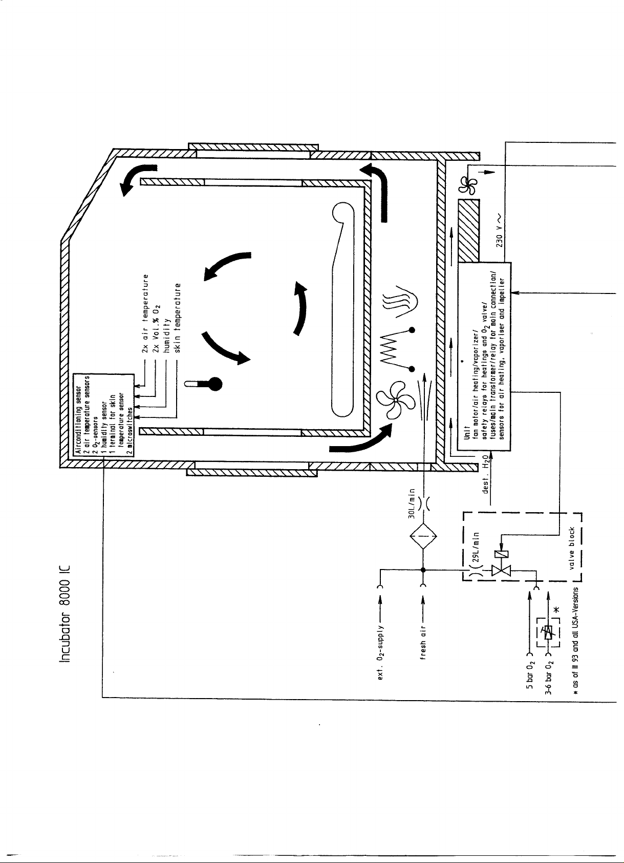
The optional oxygen control module on Incubator 8000 IC units permits the required oxygen
concentration within the canopy to be pre-selected and controlled automatically. If the actual
value deviates from the set value, warning signals are given. The control system permits a set
oxygen concentration to be achieved within a very short time (40 % in 1.5 minutes and 60 % in
< 7 minutes). This permits rapid action in emergencies and rapid return to a selected oxygen
concentration after opening the hinged front door or the hand ports.
The humidity control of the Incubator 8000 IC permits a required humidity value to be pre-
selected and maintained. The water required for this is supplied from sterile water bottles.
The humidity supply of the Incubator 8000 SC / NC humidity control can be adjusted in 10
steps.
Evaporation of the water guarantees completely hygienic air humidification.
In accordance with hygienic requirements, all parts of the Incubator which come into contact
with the gas breathed by the baby can be removed from the basic unit.
The electrically-operated height adjustment mechanism permits an optimum working height to
be set for both tall and small nurses. In addition, the Incubator can be lowered so that the
nurse can carry out lengthy procedures whilst sitting down, and there is also adequate
legroom beneath it.
The hand port openings have been designed to provide better access for the arms of the
nursing staff than round openings do, yet have a smaller opening cross-section, thus reducing
heat loss.
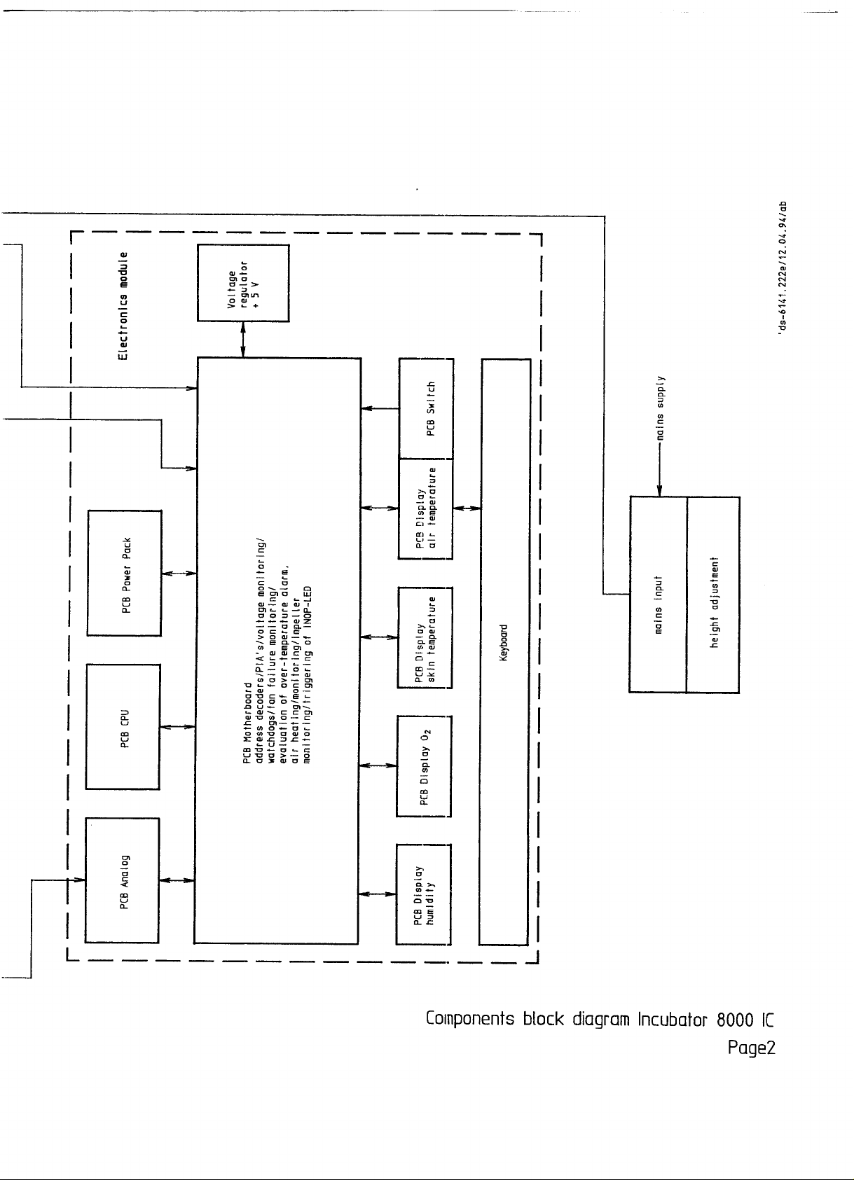
The incubator is controlled by a microprocessor. The Incubator carries out a general self-test
when it is switched on and automatically every 10 minutes thereafter. This test checks the
various assemblies in the incubator which are crucial to safety by operating them briefly. The
operator is automatically requested to recalibrate the oxygen sensors after switching on the 02
control system and, thereafter, after every 24 hours of operation. Measured value deviations or
system failures are indicated visually and audibly. The heating system and valve are
automatically switched off if operating conditions are outside permitted limits.
The control systems for air temperature, skin temperature and humidity are PI- or PID-controls
and give optimum control.
An additional built-in air-cooler produces rapid cooling as soon as the actual value of the air
temperature is a few tenths of a degree above the set value.

6141.22X Incubator 8000 IC/SC/NC Function Description 09.99 Page 5 of 49
1.2 Safety Features
A self-test is conducted when the incubator is switched on. This involves a test of all memories
in the microprocessor control system and a check to establish whether the various program
segments are running correctly.
The function of actuators, acknowledgement signals, displays and indications is checked by
switching them on and off. For example, the functioning of the fan is checked not by
establishing whether power is reaching the electric motor, but rather by measuring the speed
of rotation directly on the fan. The wiring to peripheral devices is provided in duplicate.
This complete test is also repeated every 10 minutes during operation.
All options, whether they are activated or not, are tested. An error message is thus indicated
for a faulty module even if it is switched off. This ensures that the operator is always fully
aware of the actual condition of the incubator.
When the incubator is switched on again, or when a module is switched on, the relevant
required value is set to "starting value". The set value display then flashes requesting
confirmation or modification of this value. The actual value indication is displayed alternately
with the prompt "SET" (not humidity Inc. 8000 SC / NC).
1.3 Alarms
The incubator has a graduated system of alarm signals. Faults which occur are signalled in
order of importance. If a non-essential option fails, it does not mean that the incubator has to
discontinue any functions which are of vital importance. The set value deviation and water
shortage alarms are signalled by an intermittent warning tone which can be suppressed for 10
minutes. Faults which entail greater potential danger are signalled by a continuous tone which
cannot be silenced. In addition, the relevant warning LEDs flash to enable the operator to
locate the fault rapidly. The alarm signals are described in detail below.
1.3.1 Alarm for set value deviations and water shortage
Deviations outside the set limits for oxygen concentration (> 5 % by Vol. 02), skin temperature
(> 0.5 °C with software version 10.n or 20.n and > 1.0 °C with software version 11.n and 21.n
on us units only) and air temperature (> 1.5 °C), in addition to over-temperature (> 38 °c or >
39.9 °C) and water shortage result in the following alarm signals:
- The actual value display of the relevant control module flashes.
- The specific alarm LED flashes.
- Intermittent alarm tone sounds (can be suppressed for 10 min.).
- The central alarm LED flashes (if available).

6141.22X Incubator 8000 IC/SC/NC Function Description 09.99 Page 6 of 49
The alarm tone for set value difference - 1.5 °C air temperature - is suppressed automatically
for 30 minutes when the incubator is switched on to avoid a continuous alarm signal sounding
during the warming-up phase.
The "Reset" warning button for over-temperature has to be reset by the operator to ensure full
awareness of the error. All other alarms are reset automatically when the relevant conditions
have returned to normal.
If an alarm has been suppressed, the red alarm LED, which had previously flashed, stays
alight but is constant, and a yellow LED indicator above the switch-off button indicates the
switched-off mode. If another alarm occurs when alarms are suppressed, the audible alarm is
re-activated immediately. Depending on the type of fault, this later alarm can be suppressed
again. The period for automatic reactivation of the first alarm tone is then prolonged by the
time interval between the two alarms.
1.3.2 Sensor alarms and fan failure alarm
Faults in the sensors for oxygen, skin temperature, humidity, air temperature and failure of the
fan produce the following alarm signals:
- Three dashes ("---") flash on the relevant actual value display.
- The actual air temperature value flashes in the event of fan failure.
- The specific alarm LED flashes. 0 Continuous alarm tone (non-suppressible)
- The central alarm LED flashes (if available).
Where there have been sensor warnings for oxygen concentration or relative humidity and the
relevant module has been switched off, the incubator can continue to operate with the other
functions. The same applies when there is a skin temperature control alarm, though, in this
case, the faulty sensor must be removed.
1.3.3 Module faults
Alarms for faults in the control modules for oxygen concentration, skin temperature and
relative humidity produce the following alarm signals:
- The letters "Err" (= Error) appear on the relevant actual value display, flashing if the
module is switched on and not flashing if the module is switched off.
- The red "Inop" LED is lit when the module is switched on.
- Continuous alarm tone (non-suppressible) if the module is switched on.
The functions of the other modules which are operating correctly are retained. The operator
can carry on using the incubator after the faulty module has been switched off.

6141.22X Incubator 8000 IC/SC/NC Function Description 09.99 Page 7 of 49
1.3.4 Total shutdown
Faults in the central microprocessor control system and in the air temperature control module
result in complete shutdown of the incubator. The following alarm signals are then given:
- Red "inop" LED is lit.
- Continuous alarm tone (non-suppressible).
Individual checks should be carried out to determine whether the fault appeared only
temporarily. If the incubator shows the "Inop" signal after it is switched on again, it is
inoperative. It must not be used and must be clearly marked faulty.
2 Functional description of Incubator 8000 IC / SC / NC
2.1 Description of component block diagram
- Component block diagram 8000 IC
- Component block diagram 8000 SC / NC
- Fresh air intake and 02-supply
- Unit with air heating, fan and humidifier
- Electronics module
- Climate sensor (Inc. 8000 IC only)
- Air temperature sensor (Inc. 8000 SC / NC)
- Height adjustment
2.1.1 Component block diagram 8000 IC


6141.22X Incubator 8000 IC/SC/NC Function Description 09.99 Page 10 of 49
2.1.2 Component block diagram 8000 SC / NC


6141.22X Incubator 8000 IC/SC/NC Function Description 09.99 Page 13 of 49
2.1.3 Fresh air intake and O2 supply
2.1.3.1 Fresh air intake
Through a fresh air filter 84 02 926 at the back of the Incubator 30 L/min fresh air are taken in
by dosing via the running impeller.
2.1.3.2 O2 supply
Incubator 8000 IC:
There are two possibilities for 02 supply in Incubator 8000 IC:
a. External 02-supply
b. Oxygen control
Incubator 8000 SC / NC:
With Incubator 8000 SC / NC only external 02-supply (a.) is possible.
a. external O2 supply
Via a socket oxygen can be supplied to the Incubator through a flowmeter. According to
specification the oxygen concentration has to be monitored with an additional oxygen
measuring instrument with upper and lower alarm limit.
b. oxygen control
An automatic control can be carried out with the integrated 02 concentration control. According
to set value deviation one valve with 29 L/min is opened by the electronic control. According to
specification the oxygen is supplied via the fresh air filter to the patient room.
2.1.4 Heating unit
The following function blocks are on the unit:
- fan motor
- air heating with over-temperature fusing
- humidifier with over-temperature fusing
- mains transformer
- auxiliary mains transformer for mains connection
- semiconductor relay for air heating and humidifier
- safety relay for heatings and 02 valves
- Sensor for monitoring of:
the air heating (I/U converter)
the vaporizer (temperature for water shortage alarm)
the impeller (fan)
- fuses for the mains input and the internal supply voltages

6141.22X Incubator 8000 IC/SC/NC Function Description 09.99 Page 14 of 49
2.1.5 Electronics module
The electronics module comprises the following function blocks:
- keyboard
- PCB Display Air Temperature:
a. triggering of display elements for air temperature control
b. read-out of keyboard
- PCB Display Options and PCB Display Humidity/Skin Temperature:
triggering of the individual display elements of the options
- PCB CPU:
a. processor 6802
b. EPROM
c. RAM with internal battery for data backup
d. timer
e. watchdog
- PCB Analog
a. reading in of measured values of climate sensor housing (Inc. 8000 IC) or of
air temperature sensor (Inc. 8000 SC / NC)
b. reading in of climate sensor housing position (Inc. 8000 IC)
c. processor-dependent monitoring circuit for over-temperature and existence of oxygen
sensors
d. processor-dependent monitoring circuit forpresence of oxygen sensors (Inc. 8000 IC)
- PCB Power Pack
a. Rectification of supply voltage +15 V and -15 V
b. Rectification and control of supply voltage +5 V. The voltage regulator is positioned on
the right hand side panel of the electronics module.
c. Charaino circuit for battery of the mains failure-alarm.
d. Trigger circuit for horn and mains failure LED
e. Horn
- Motherboard
a. Address decoder for peripherals
b. PIAs for triggering of peripherals
c. Evaluation of over-temperature alarm
d. Fan failure monitoring
e. Watchdogs
f. Voltage monitoring
g. Evaluation of air heating monitoring
h. Evaluation of impeller monitoring

6141.22X Incubator 8000 IC/SC/NC Function Description 09.99 Page 15 of 49
i. Evaluation of valve monitoring
j. Triggering of INOP-LED
k. Triggering of additional fan
2.1.6 Climate sensor housing (Inc. 8000 IC)
This sensor detects the climatic conditions inside the incubator. For calibration of the 02
measurement function the sensor can be swung out of the incubator interior.
Function blocks:
- 2 air temperature sensors
- 2 02 sensors
- Terminal for skin temperature sensor (units with software version 20.n only)
- Humidity sensor with evaluation electronics
- 2 micro switches to determine sensor position
2.1.7 Air temperature sensor (Inc. 8000 SC / NC)
For measurement of the air temperature two identical sensors are enclosed in one housing.
2.1.8 Height adjustment
The height is adjusted via an Electro-motor with spindle. The pedestal is triggered via a foot-
operated switch. The Electro-motor is equipped with an automatically resettable over-
temperature switch.
2.2. Description of block diagram of electronic functioning
2.2.1 Incubator 8000 IC / SC / NC block diagrams


6141.22X Incubator 8000 IC/SC/NC Function Description 09.99 Page 20 of 49
2.2.2 Detailed description of block diagram
The numbers in brackets refer to the position in the block diagram.
2.2.2.1 Air temperature sensor (39)
The air temperature sensor is part of the feedback loop of an operational amplifier (31B). This
operational amplifier produces an output voltage proportional to the air temperature. A second
amplifier stage modifies the voltage to the input voltage range of the ADC. Resolution: 0.0 °C
to 60.0 °C = 0.0 to 5.0 V.
2.2.2.2 Over-temperature sensor (38)
The over-temperature sensor is mechanically integrated with the air temperature sensor in one
housing. This allows a redundant measurement for the air temperature. The amplification
factor and thus the output signal differs from the output signal of the air temperature sensor.
The air and over-temperature sensor are checked crosswise by software. In case of a
temperature difference of more than 0.5 °C a sensor alarm is produced. The over-temperature
sensor is placed in the feedback loop of the operational amplifier (31A). A second amplifier
stage modifies the voltage to the input voltage range of the ADC. Resolution: 0.0 to 50.0 °C =
0.0 to 5.0 V.
2.2.2.3 Over-temperature comparator (29)
The output voltage of the over-temperature sensor circuit is additionally monitored by a
comparator. The trigger level of this comparator is set to 40.0 °C. If the over-temperature
sensor output voltage reaches this limit independent and unaffected by the microprocessor
this comparator switches off the heater and sets the incubator into the safe operation mode.
The over-temperature condition is stored and latched by a bipolar relay (16). After the
temperature has fallen and the over-temperature sensor circuit is reset by the operator with a
dedicated reset button, normal operation of the temperature control system is continued.
2.2.2.4 Testing of over-temperature comparator (36)
Every 10 minutes the over-temperature sensor circuit (comparator) is tested by the
microprocessor. On the Analog PCB the relay (K2) or by FET transistors on newer devices as
of 1996 substitutes for a short time the over-temperature sensor with a fixed resistor simulating
a temperature higher than 40.0 °C.
Other manuals for Incubator 8000 IC
3
This manual suits for next models
2
Table of contents
Other Dräger Accessories manuals

Dräger
Dräger 68 09 381 User manual

Dräger
Dräger Polytron 8200 User manual

Dräger
Dräger Isolette 8000 plus User manual

Dräger
Dräger Polytron 8100 User manual

Dräger
Dräger PEX 3000 User manual

Dräger
Dräger Polytron SE Ex PR M2 DD User manual

Dräger
Dräger Incubator 8000 IC User manual

Dräger
Dräger caleo Configuration guide

Dräger
Dräger DOL 53 Manual

Dräger
Dräger Incubator 8000 IC User manual