manuals.online logo
Brands
  1. Home
  2. •
  3. Brands
  4. •
  5. Dräger
  6. •
  7. Accessories
  8. •
  9. Dräger X-am 3500 User manual

Dräger X-am 3500 User manual

Other manuals for X-am 3500

3

This manual suits for next models

1

Other Dräger Accessories manuals

Dräger caleo Configuration guide

Dräger

Dräger caleo Configuration guide

Dräger Incubator 8000 IC User manual

Dräger

Dräger Incubator 8000 IC User manual

Dräger Polytron SE Ex PR M2 DD User manual

Dräger

Dräger Polytron SE Ex PR M2 DD User manual

Dräger Polytron 8100 User manual

Dräger

Dräger Polytron 8100 User manual

Dräger SE Ex PR M User manual

Dräger

Dräger SE Ex PR M User manual

Dräger PEX 3000 User manual

Dräger

Dräger PEX 3000 User manual

Dräger Incubator 8000 IC Parts list manual

Dräger

Dräger Incubator 8000 IC Parts list manual

Dräger DragerSensor IR User manual

Dräger

Dräger DragerSensor IR User manual

Dräger X-pid 800 Series User manual

Dräger

Dräger X-pid 800 Series User manual

Dräger Polytron 8200 User manual

Dräger

Dräger Polytron 8200 User manual

Dräger DOL 53 Manual

Dräger

Dräger DOL 53 Manual

Dräger Isolette 8000 plus User manual

Dräger

Dräger Isolette 8000 plus User manual

Dräger Incubator 8000 IC User manual

Dräger

Dräger Incubator 8000 IC User manual

Dräger 68 09 381 User manual

Dräger

Dräger 68 09 381 User manual

Dräger Polytron SE Ex PR NPT1 DD User manual

Dräger

Dräger Polytron SE Ex PR NPT1 DD User manual

Dräger PID 5000 User manual

Dräger

Dräger PID 5000 User manual

Popular Accessories manuals by other brands

Quincy lab 140AE-1 operating manual

Quincy lab

Quincy lab 140AE-1 operating manual

HomePro ZIR000 user manual

HomePro

HomePro ZIR000 user manual

DOL 20SCR Technical user guide

DOL

DOL 20SCR Technical user guide

RAB Smart Task installation manual

RAB

RAB Smart Task installation manual

Kemppi KMS 300 quick guide

Kemppi

Kemppi KMS 300 quick guide

Stearns 57,500 Series Installation and service instructions

Stearns

Stearns 57,500 Series Installation and service instructions

iGuzzini TWILIGHT COPENAGHEN manual

iGuzzini

iGuzzini TWILIGHT COPENAGHEN manual

Adelaide Annexe & Canvas Avan Deluxe installation guide

Adelaide Annexe & Canvas

Adelaide Annexe & Canvas Avan Deluxe installation guide

OHAUS 5000 instruction manual

OHAUS

OHAUS 5000 instruction manual

HOME8 WLS1300 quick start guide

HOME8

HOME8 WLS1300 quick start guide

MAXBOTIX MaxSonar quick start guide

MAXBOTIX

MAXBOTIX MaxSonar quick start guide

ioSmart iSmart56 Installation and user guide

ioSmart

ioSmart iSmart56 Installation and user guide

Focusrite Scarlett 18i8 user guide

Focusrite

Focusrite Scarlett 18i8 user guide

Velleman ED38105 user manual

Velleman

Velleman ED38105 user manual

JumpSport SkyBounce user manual

JumpSport

JumpSport SkyBounce user manual

Prima-Temp PRIYA Instructions for use

Prima-Temp

Prima-Temp PRIYA Instructions for use

Tefcold BC85I-BC85I W user manual

Tefcold

Tefcold BC85I-BC85I W user manual

Vaisala WMS302 user guide

Vaisala

Vaisala WMS302 user guide

manuals.online logo
manuals.online logoBrands
  • About & Mission
  • Contact us
  • Privacy Policy
  • Terms and Conditions

Copyright 2025 Manuals.Online. All Rights Reserved.

X-am 3500 / 8000 │Notes on approval / Sensor data
Edition 04 - June 2019 - 90 33 655
Declaration of conformity for X-am 3500 / 8000Approvals / Marking
X-am 3500
X-am 8000
Serial No. 1)
Only for USA:
Changes or modifications not expressly approved by the party res-
ponsible for compliance could void the user's authority to operate
the equipment.
This equipment has been tested and found to comply with the limits
for a Class B digital device, pursuant to part 15 of the FCC Rules.
These limits are designed to provide reasonable protection against
harmful interference in a residential installation. This equipment ge-
nerates, uses and can radiate radio frequency energy and, if not in-
stalled and used in accordance with the instructions, may cause
harmful interference to radio communications. However, there is no
guarantee that interference will not occur in a particular installation.
If this equipment does cause harmful interference to radio or televi-
sion reception, which can be determined by turning the equipment
off and on, the user is encouraged to try to correct the interference
by one or more of the following measures:
Reorient or relocate the receiving antenna.
Increase the separation between the equipment and receiver.
Connect the equipment into an outlet on a circuit different from
that to which the receiver is connected.
Consult the dealer or an experienced radio/TV technician for
help.
This device complies with part 15 of the FCC Rules. Operation is
subject to the following two conditions:
(1) This device may not cause harmful interference, and
(2) this device must accept any interference received, including in-
terference that may cause undesired operation.
FCC responsible party:
Draeger Inc.
7256 S. Sam Houston W. Parkway
Suite 100
Houston, Tx 77085 USA
phone: +1 346-802-6111
e-mail: DIHouston.Approvals@draeger.com
Only for Canada:
CAN ICES-3 (B)/NMB-3(B)
Only for CSA (Canadian Standards Association):
WARNING: Wireless communication is intended for use as a se-
condary remote alarm status notification only. Primary alarming of
combustible gas hazards is provided locally by detector.
WARNING: Applicable to CLASS II DIV.1, GROUPS E, F, and G
certification: CSA Std. 152 does not have any requirement for Class
II environment and therefore this device has not been performance
tested for Class II hazardous location. The sensor may become
clogged and not detect gas properly or warn the user of its inability
to detect gas.
AVERTISSEMENT: La communication sans fil est destinée à être
utilisée uniquement comme notification d'état d'alarme secondaire
à distance. L'alarme primaire des risques de gaz combustible est
fournie localement par le détecteur.
AVERTISSEMENT: Applicable à la certification CLASSE II DIV.1,
GROUPS E, F et G: CSA Std. 152 n'a pas d'exigence pour l'en-
vironnement de classe II et par conséquent, cet appareil n'a pas été
testé pour un emplacement dangereux de Classe II. Le capteur
peut se boucher et ne pas détecter correctement le gaz ou avertir
l'utilisateur de son incapacité à détecter le gaz.
1) Serial Number key: The third letter of the serial number specifies the
manufacturing year: M = 2019, N = 2020, P = 2021, R = 2022, S = 2023,
T = 2024, U = 2025, W = 2026, X = 2027, Y = 2028,
Z = 2029, etc. (Letters G, I, O, Q are omitted)
Example: Serial Number ARMB-0001: the third letter is M, which means
that the unit was manufactured in 2019.
P/N: XXXXXXX
S/N: ARXX-XXXX
Use only power supply
Dräger LBT 02**
X-am 3500
0158
I M1 / II 1G
Ex da ia I Ma
Ex da ia IIC T4 Ga
TC RU C-DE.BH02.B.00744
PO Ex da ia I Ma X
0Ex da ia IIC T4 Ga X
&7D&
18.70148494
IECEx BVS 17.0034X
BVS 17 ATEX E 040 X
PFG 19 G 001X
&7D&
Class I, Zone 0, A/Ex da ia IIC T4 Ga
Class II, Div. 1, Groups E, F, G
C22.2 No. 152 for comb. sensors, Class I only
Type: HFG 0000
data
matrix
code
IP 67
P/N: XXXXXXX
S/N: ARXX-XXXX
Use only power supply
Dräger LBT 02**
X-am 8000
0158
I M1 / II 1G
Ex da ia I Ma
Ex da ia IIC T4 Ga
TC RU C-DE.BH02.B.00535
PO Ex da ia I Ma X
0Ex da ia IIC T4 Ga X
&7D&
18.70148494
IECEx BVS 17.0034X
BVS 17 ATEX E 040 X
PFG 19 G 001X
&7D&
Class I, Zone 0, A/Ex da ia IIC T4 Ga
Class II, Div. 1, Groups E, F, G
C22.2 No. 152 for comb. sensors, Class I only
Type: HFG 0010
data
matrix
code
IP 67
90 33 655 - ED 4836.300 Dräger Safety AG & Co. KGaA
©Dräger Safety AG & Co. KGaA Revalstraße 1 Tel +49 451 882 0
Edition 04 - June 2019 (Edition 01 - June 2017) 23560 Lübeck, Germany Fax +49 451 882 20 80
Subject to alteration www.draeger.com
Sensor data
Excerpt: For details, see instructions for use/data sheets for the respective sensor.
The instructions for use, technical manual and data sheets for the utilized sensors can be downloaded from: www.draeger.com/ifu and the PC software CC-Vision from: www.draeger.com/
software
For the conversion of the test gas concentration between %LEL and Vol.% see Information system on hazardous substances (GESTIS) of the German Social Accident Insurance (IFA)
https://www.dguv.de/ifa/gestis/gestis-stoffdatenbank/index-2.jsp or LEL values in accordance with EN 60079-20-1.
Note:
The requirements of the standards regarding error limits are valid for the whole operating range of the device, deviations are:
XXS H2 HC sensor, increased indication at -20 °C; ≤4.5 %LEL between -10 °C and +50 °C
XXS CO-LC sensor, increased indication at >40 °C; at zero-point <=7 ppm, test gas concentration ≤27 %
Dual IR Ex Sensor at measuring range 0-5 vol.% methane (CH4), the deviation from the volume fraction at 1.46 vol.% CH4 caused by added 0.075 vol.% ethane (C2H6) in air, is about + 25 % rel.
In sub-zero temperatures, the response times of the XXS CO-LC and XXS O2 sensor may be increased compared to room temperature. If necessary, check response times (see instructions for use).
DUAL IR Ex / CO2
6811960
CatEx 125 PR
6812950
CatEx 125 PR
Gas
6813080
XXS H2S-LC
6811525
XXS H2-HC
6812025
XXS O2
6810881
XXS CO-LC
6813210
IR Ex
6812180
IR CO2
6812190
X-am 3500/8000 X-am 8000 X-am 3500/8000 X-am 8000 X-am 3500/8000 X-am 3500/8000 X-am 8000 X-am 8000
Measuring principle Catalytic combusti-
on
Catalytic combusti-
on
Electrochemical Electrochemical Electrochemical Electrochemical Infrared Infrared
Indication range 0 to 100 %LEL 0 to 100 %LEL
0 to 100 vol.%
(CH4)
0 to 100 ppm 0 to 100 %LEL 0 to 25 vol.% 0 to 2000 ppm 0 to 100 %LEL
0 to 100 vol.%
(CH4)
0 to 5 vol.%
Measuring range (certified) 0 to 100 %LEL1)
1) CatEx 125 PR: alkanes from methane to n-Octan.
CatEx 125 PR Gas: methane, propane, ethane, ethene, ethine, propene, n-butane, i-butene, hydrogen.
LEL values in accordance with EN 60079-20-1. At air speed of 0 to 6 m/s, the deviation of the reading is 5 to 10 % of the measured value.
0 to 100 %LEL1)
0 to 5 vol.%
0.4 to 100 ppm 0 to 100 %LEL 0 to 25 vol.% 3 to 500 ppm 0 to 100 %LEL2)
0 to 5 vol.% (CH4)
2) IR Ex: methane, propane, n-nonane; LEL values in accordance with EN 60079-20-1.
0.05 to 5 vol.%
Capture range3)
3) This range of measured values is known as capture range where minor measured value fluctuations (e.g. signal noise, concentration fluctuations) does not result in a changing display. Measured values
outside the capture range are displayed using their actual measured values. By using Dräger CC-Vision the set capture range can be read out and activated/deactivated. By default, the capture range
is continuously activated in measuring mode and is disabled in calibration mode.
+2 to -5 % LEL +2 to -5 % LEL ±0.4 ppm ±0.5 %LEL ±0.4 vol.% ±1.4 ppm ±1 %LEL 390 ppm
±100 ppm
Drift per month ±1 %LEL (CH4)
±3 %LEL (C3H8)
±1 %LEL (CH4)
±2 %LEL (C3H8)
1.9 % of
measured value
±4 %LEL ±1 % of
measured value
1.2 % of
measured value
±2 %LEL (CH4)
±1 %LEL (C3H8)
±0.8 % of
measured value
Warm-up time 85 s 85 s 85 s 85 s 120 s 85 s 85 s 85 s
Effect of sensor poisons
HMDS, 10 ppm
hydrocarbons, heavy metals, and
substances containing silicone, sul-
phur or polymerisation
1 %LEL/
8 h
Possible poisoning
1 %LEL/
8 h
Possible poisoning
n/a n/a n/a n/a n/a n/a
Linearity error 2 %LEL (CH4)
5 %LEL (C3H8)
4 %LEL (CH4)
1 %LEL (C3H8)
0.1 % of
measured value
±1.5 %LEL 0.3 vol.% 1.2 % of
measured value
2 %LEL (CH4)
3 %LEL (C3H8)
7.8 % of
measured value
Standards
Measuring function for flammable
gases, oxygen deficiency / enrich-
ment and toxic gases, DEKRA
Testing and Certification GmbH:
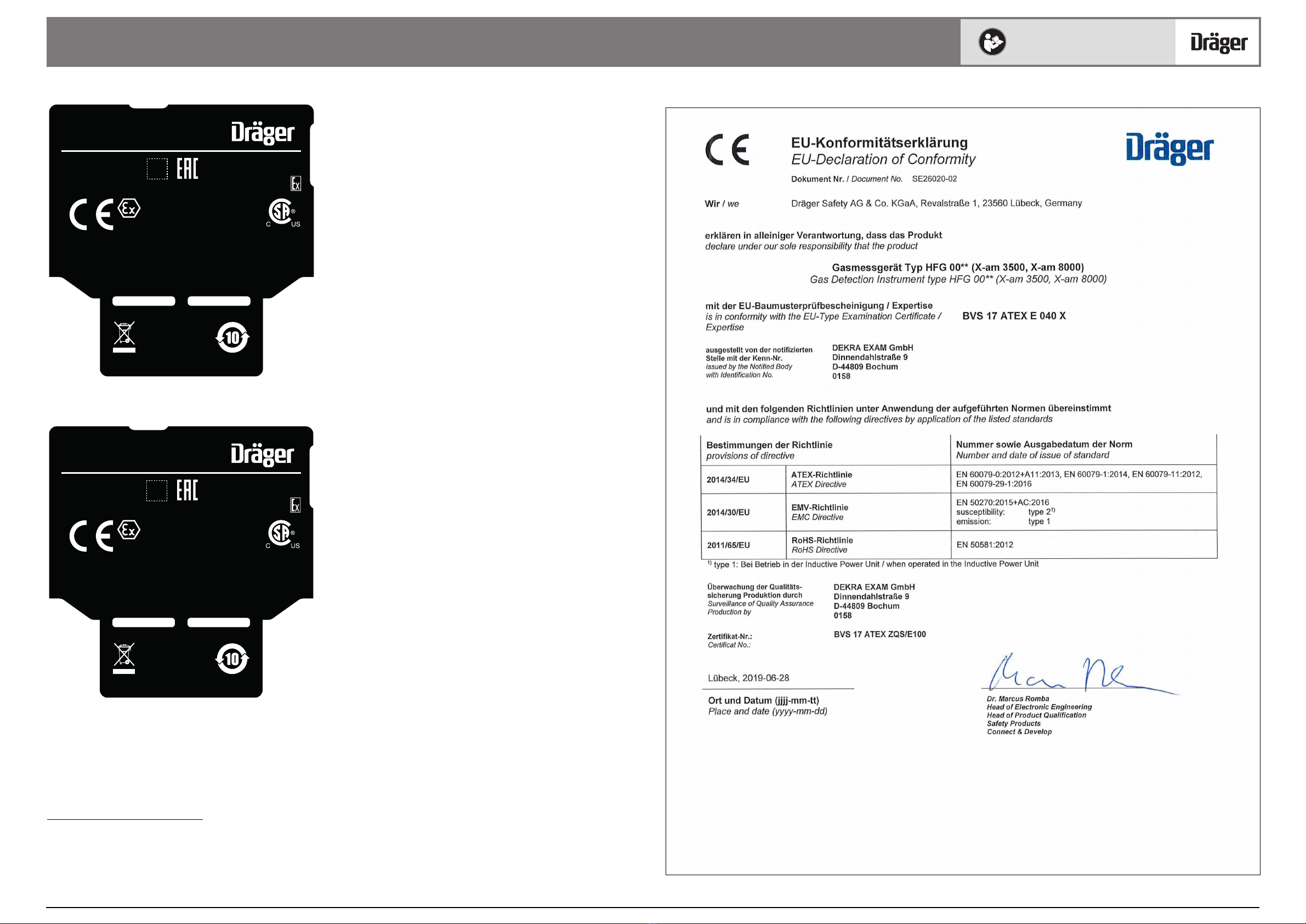
BVS 17 ATEX E 040 X 1),
PFG 19 G 001 X
EN 60079-29-1
EN 50271
EN 60079-29-1
EN 50271
EN 45544-1
EN 45544-2
EN 45544-3
EN 50271
EN 60079-29-1
EN 50271
EN 50104
EN 50271
EN 45544-1
EN 45544-2
EN 45544-3
EN 50271
EN 60079-29-1
EN 50271
EN 45544-1
EN 45544-2
EN 45544-3
EN 50271
Cross-sensitivities exist4)
4) The instrument responds to most combustible gases and vapours. The sensitivities differ depending on the type of gas. Dräger recommends a calibration using the target gas to be measured. Regarding
catalytic combustion sensors in the range of alkanes, the sensitivity decreases from methane to nonane. The sensitivity ratios between different gases can change as a result of sensor aging or poiso-
ning.
exist4) Additively affected
by:
SO2, NO2, H2
Negatively affec-
ted by
: Cl2
Additively affected
by: C2H2, NO, CO
Increased hydro-
gen concentra-
tions within the
range of XXS H2
HC may result into
false alarms by ad-
ditive effect on the
XXS H2S and the
XXS CO, as well as
due to the negative
effect on the XXS
O2
Negatively affec-
ted by:
C2H6, C2H4, C2H2,
CO2, H2
No O2measure-
ment in He
Additively affected
by:
C2H2, H2, NO
exist4) n/a
Diffusion
Time of response t0...90 20 s (CH4)
30 s (C3H8)
15 s (CH4)
29 s (C3H8)
20s 15s 9 s 21 s 21 s (CH4)
57 s (C3H8)
48 s
Time of response t0...50 (Ex, Tox)
Time of response t0...20 (O2)
9 s (CH4)
12 s (C3H8)
8 s (CH4)
12 s (C3H8)
14 s 10 s 5 s 13 s 10 s (CH4)
14 s (C3H8)
14 s
Time of recovery t0...10 17 s (CH4)21 s n/a 21 s 30 s (CH4)47 s
Time of recovery t0...50 7 s (CH4)14 s n/a 12 s 10 s (CH4)15 s
Pump
Time of response t0...90 12 s (CH4)
15 s (C3H8)
10 s (CH4)
13 s (C3H8)
20 s 15 s 8 s 16 s 11 s (CH4)
15 s (C3H8)
14 s
Time of response t0...50 (Ex, Tox)
Time of response t0...20 (O2)
9 s (CH4)
11 s (C3H8)
8 s (CH4)
10 s (C3H8)
15 s 11 s 6 s 11 s 9 s (CH4)
10 s (C3H8)
10 s
Time of recovery t0...10 10 s (CH4)20 s n/a 16 s 11 s (CH4)14 s
Time of recovery t0...50 8 s (CH4)14 s n/a 12 s 9 s (CH4)10 s
Calibration adapter
Time of response t0...90 35 s (C8H18)23 s other
certified gases
160 s (C9H20)
Time of response t0...50 100 s (C8H18)12 s other
certified gases
28 s (C9H20)