Installation
Dräger Polytron 8200/8310 7
2.3.3 Dräger Polytron 8310 with DrägerSensor IR
Infrared sensor for monitoring flammable gases and vapors
containing hydrocarbons
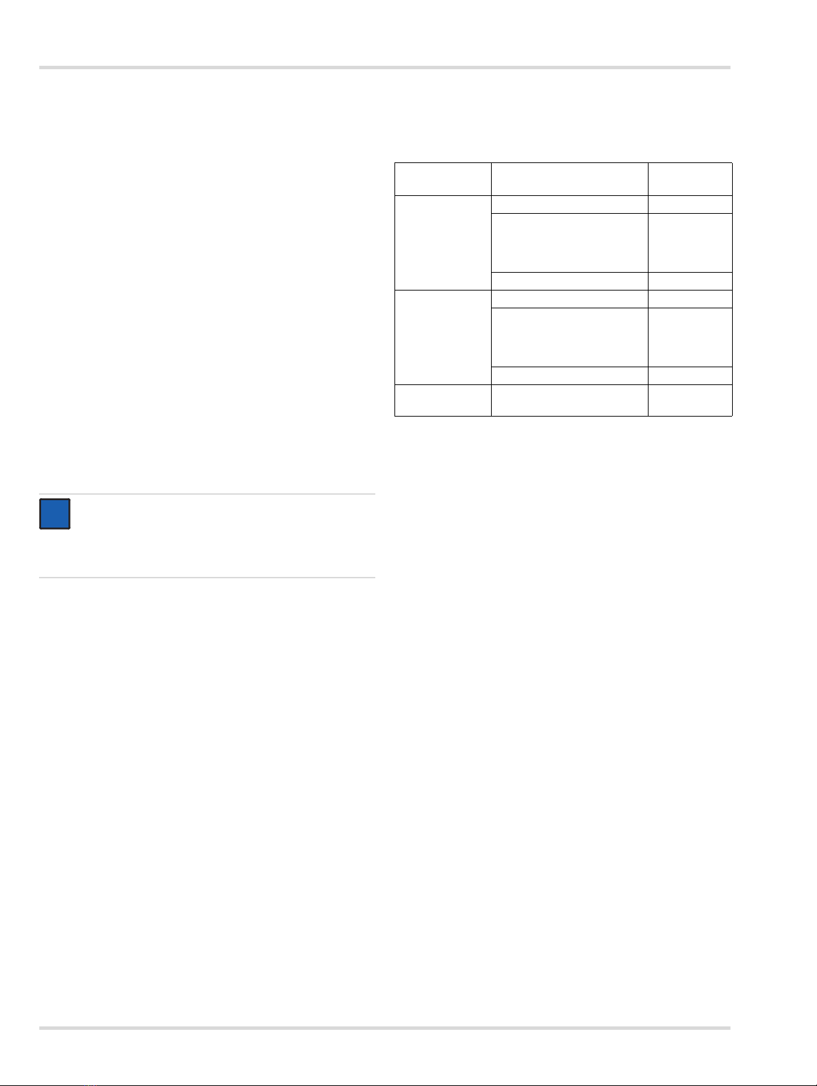
{Detection range: 0 to 100 % LEL 2)
2.4 Intended operating area and operating
conditions
Hazardous areas classified by zones:
The device is only designed for use in Zone 1 or Zone 2
potentially explosive atmospheres for which a temperature
range as specified on the device must be observed and in which
gases of Explosion Groups IIA, IIB or IIC and Temperature
Classes T4 or T6 (depending on maximum ambient
temperature) or dust of Groups IIIA, IIIB or IIIC may occur.
Hazardous areas classified by divisions:
The device is only designed for use in potentially explosive
atmospheres of Classes I&II, Div. 1 or 2, for which
a temperature range as specified on the device must be
observed and in which gases or dust of Groups A, B, C, D or
E, F, G and Temperature Classes T4 or T6 (depending on
maximum ambient temperature) may occur.
2.5 Approvals
See printed version for approval markings.
2.6 Device marking
The device marking is supplied with the device as a copy on
a separate document.
Key to the Serial Number: The third letter of the Serial Number
specifies the year of manufacture: A = 2009, B = 2010, C = 2011,
D = 2012, E = 2013, F = 2014, H = 2015, J = 2016, K = 2017 etc.
Example: Serial Number ARBH-0054: The third letter is B,
i.e. the device was manufactured in 2010.
3 Installation
3.1 General information for the installation
The selection of a suitable mounting location is crucial for
the effectiveness and performance of the entire system. Every
detail of the installation must be thoroughly thought out.
The following must be noted in particular:
zthe local and national rules and regulations for the
installation of gas monitoring systems,
zthe applicable regulations for running and connecting
power and signal cables to gas monitoring systems,
zthe full extent of environmental influences to which the
device will be subjected,
zthe physical properties of the gases and vapors to be
measured,
zthe details of the particular application (e.g., potential
leaks, air movements/flows, etc.),
zaccessibility for required maintenance activities,
zthe geometric of the accessories that are used with the
system,
zall other limiting factors and stipulations that may affect the
installation of the system.
zFor installation without a conduit, an approved cable gland
(e.g. Hawke A501/421/A/¾" NPT or equivalent) must be
used (see chapter 12 on page 28). To increase the RF
interference immunity, it may be necessary to connect the
cable screen to the cable gland and to the control unit.
zThe explosion proof enclosure has three ¾" NPT
connections, which can be used for field wiring, the direct
attachment of a sensor or wiring an external sensor.
Unused openings must be closed off with a plug. For the
correct tightening torques for cable bushings, plugs,
sensors and connectors, see chapter 12 on page 28.
zThe secondary are supposed to be supplied from an
isolating source (does not apply to relay contacts).
zThe optional e-Box has up to four 20 mm connections,
which can be used for field wiring or wiring an external
sensor. The permissible cable diameter is 7 to 12 mm.
zIf the device is installed in locations where ambient
temperatures of over 55 °C prevail, appropriate cables
which are specified for use at temperatures of 25 °C above
the maximum ambient temperature must be used.
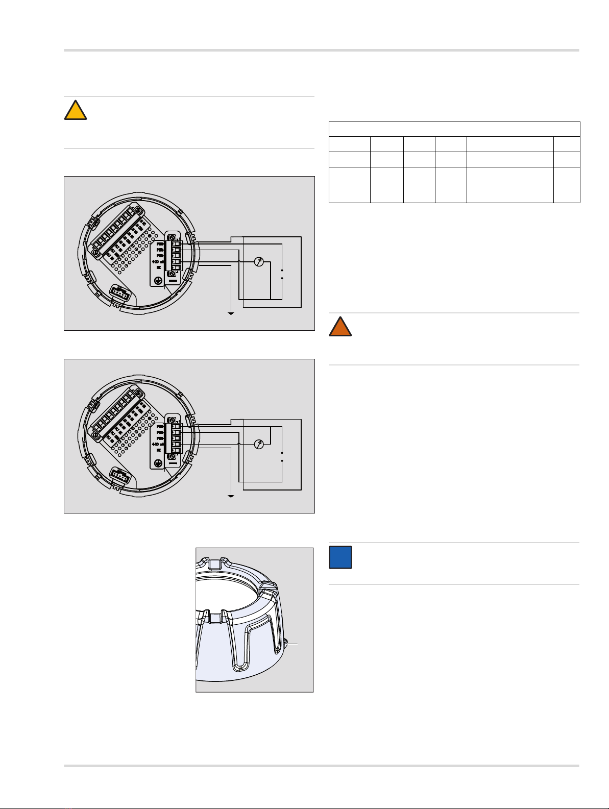
zStrip back the insulation on conductors by 5 to 7 mm.
zConnect the cable as shown in Chapter 3.5 on page 9
(shown here also with protective ground) oder Chapter 3.6
on page 10.
zThe connecting wires for the optional relay module must be
selected and fused according to the rated voltages,
currents and environmental conditions.
zWhen stranded conductors are used, an end ferrule must
also be used.
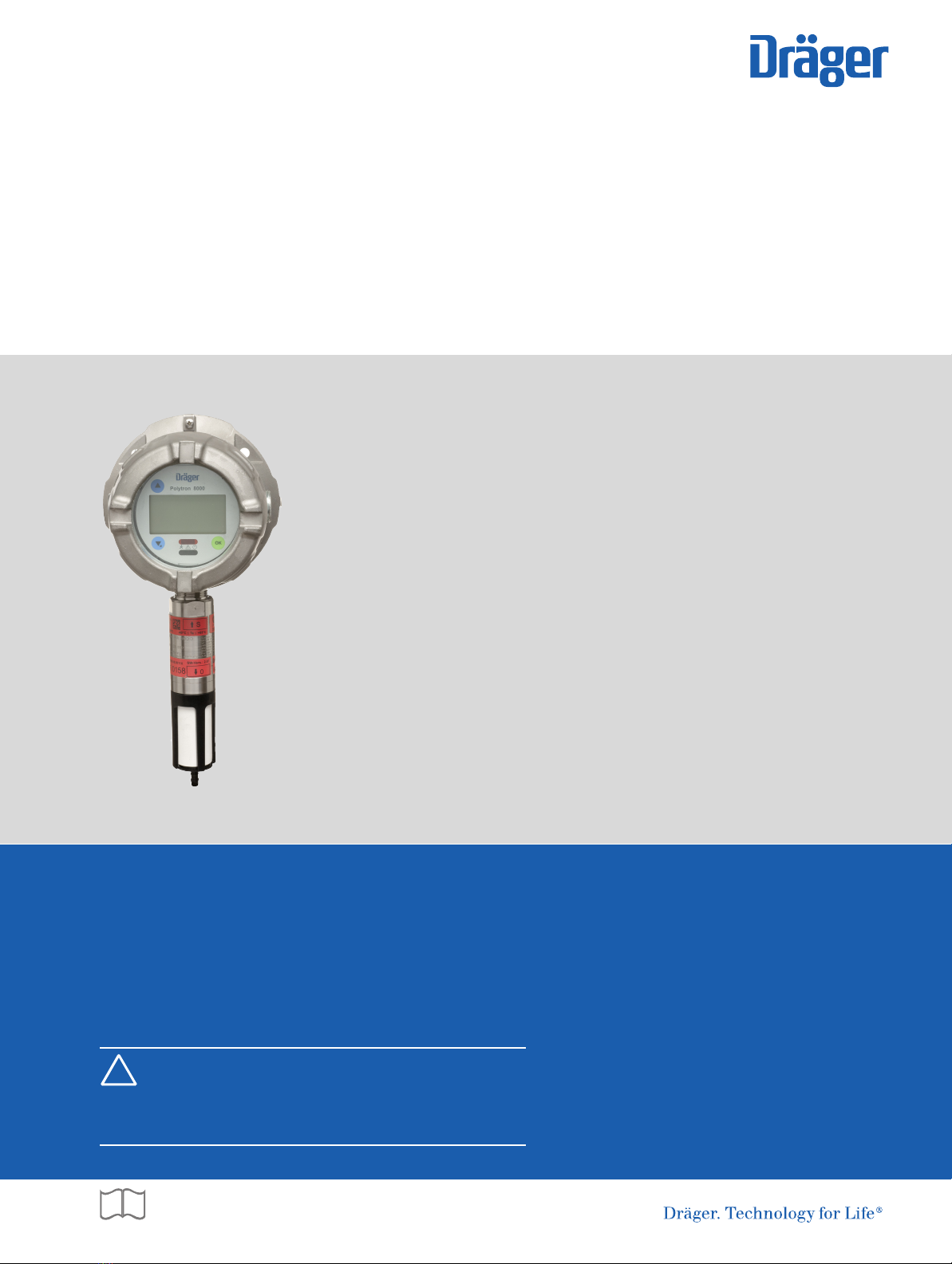
WARNING
Explosive. Not to be used in oxygen enriched
atmospheres. None of the Polytron 8000 transmitters
is certified and approved to be operated in oxygen
enriched atmospheres.
!
DPolytron 8200
ETR 0400
Dräger Safety 23560 Lübeck, Germany
II 2G
II 2D
WARNING: Do not open when energized
I
S
F
S
I
E
A
D
L
C
9N54
0158
Class I, Div 1, Groups A,B,C,D | Class II, Div 1, Groups E,F,G
Class I, Zone 1, Group IIC | T-Code T6/T4 | Type 4X
Supply: 16...30 VDC, 4...20 mA
CAUTION: Do not open cover. Opening
cover with circuits alive provokes risk of
Ignition of Hazardous Atmospheres.
WARNING: To reduce the risk of Ignition
of Hazardous Atmospheres, the conduit
must be sealed within 18’’ of the enclosure.
WARNING: Read Manual before operating.
Gas Detector for Use in Hazardous Locations as to
Fire, Electrical Shock and Explosion Hazards only
Part No: 4544440
Serial No. XXXX-9999
Ex d IIC T6/T4 Gb
Ex tb IIIC T80/130°C Db
-40°C ≤ Ta ≤ +40/+80°C
PTB 11 ATEX 1005X
IECEx PTB 11.0005X
IP6x | P ≤ 5 W