DSC GS3125 Series User manual

GS3125/GS3105
GSM/GPRS Alarm Communicators
SS
SS
S
II
II
I
GG
GG
G
GSM/GPRS Uppringare
Comunicatori di Allarme GSM/GPRS

No. GParts S Del IParti
1GSM Antenna GSM Antenn Antenna GSM
2Magnetic base Magnetfot Base magnetica
3Antenna cable Antennkabel Cavo antenna
4Connector SMA for GSM
Antenna Antennfäste (SMA) Connettore SMA per
antenna GSM
5Status LEDs Statusdioder LED di controllo
6SIM holder Simkortshållare Porta SIM-CARD
7P.C.B. fixing holes Hål för distanser Fori di fissaggio scheda
8SIM CARD Simkortshållare SIM-CARD
9Connection cable for
programming via PC Stift för anslutning till PC Connettore cavo per la
programmazione da PC
10 Terminal Blocks Kopplingsplint Morsettiere per
collegamenti
11 Antenna cable feed
opening Kabelgenomföringshål Apertura per passaggio
cavo antenna
12 Metal bracket fixing holes Skruvhål Fori di fissaggio staffa
metallica
13 Metal bracket Monteringsbygel Staffa metallica
14 Adesive plastic support Självhäftande
plastdistanser Supporto plastico adesivo
15 Tamper switch (optional) Sabotagekontakt (valfritt) Deviatore antisabotaggio
(opzionale)
16 P.C.B. support P.C.B. distanser Supporto scheda
17 Metal base Metallhölje Fondo metallico
18 Cover Frontstycke Coperchio
19 Base fixing holes Monteringshål Fori di fissaggio del fondo
20 Tamper switch fixing pins Monteringshål
sabotagekontakt
Perni di fissaggio del
Deviatore Antisabotaggio
21 Tamper switch fixing nuts Muttrar Dadi per il fissaggio del
Deviatore Antisabotaggio
22 Cable feed opening on the
base Kabelgenomföringshål Apertura, sul fondo, per
passaggio cavi
23 Antenna wire feed opening
on the base Antennens genomföringshål Apertura, sul fondo, per
passaggio cavo antenna
24 Cover fixing holes Lockets skruvhål Fori di fissaggio del
coperchio
25 Cover fixing screws Skruvar för locket Viti di fissaggio del
coperchio
26 Cable clamp tab Kabelfixering Linguetta fermacavo
27 Holes for the insertion of
P.C.B. supports Hål för distanser Fori per l'inserimento dei
supporti scheda

Fig. 1 - Parts - Komponenter - Identificazione delle parti
GS3105-K/GS3125-K
GS3105-BA/GS3125-BA
GS3100-BX
2
1
25
16
16
27
2719
19
19
15
20
20
22
21
25
21
9
7
7
7
7
6
8
24
24
18
26
27
27
19
23
2
3
17
4
10
10
25
27
27
19
19
19
20
20
22
25
24
24
18
1
2
16
3
1
12 12
11
13
2
3
14
4
7
7
7
9
7
10
10
5
6

4GSM/GPRSAlarm Communicators
TABLE OF CONTENTS
To program this device use the software GS3100 Series Console ver. 3.0 or higher.
INTRODUCTION .............................................................. 5
Features .................................................................................. 5
Technical Specifications ........................................................... 5
Description .............................................................................. 6
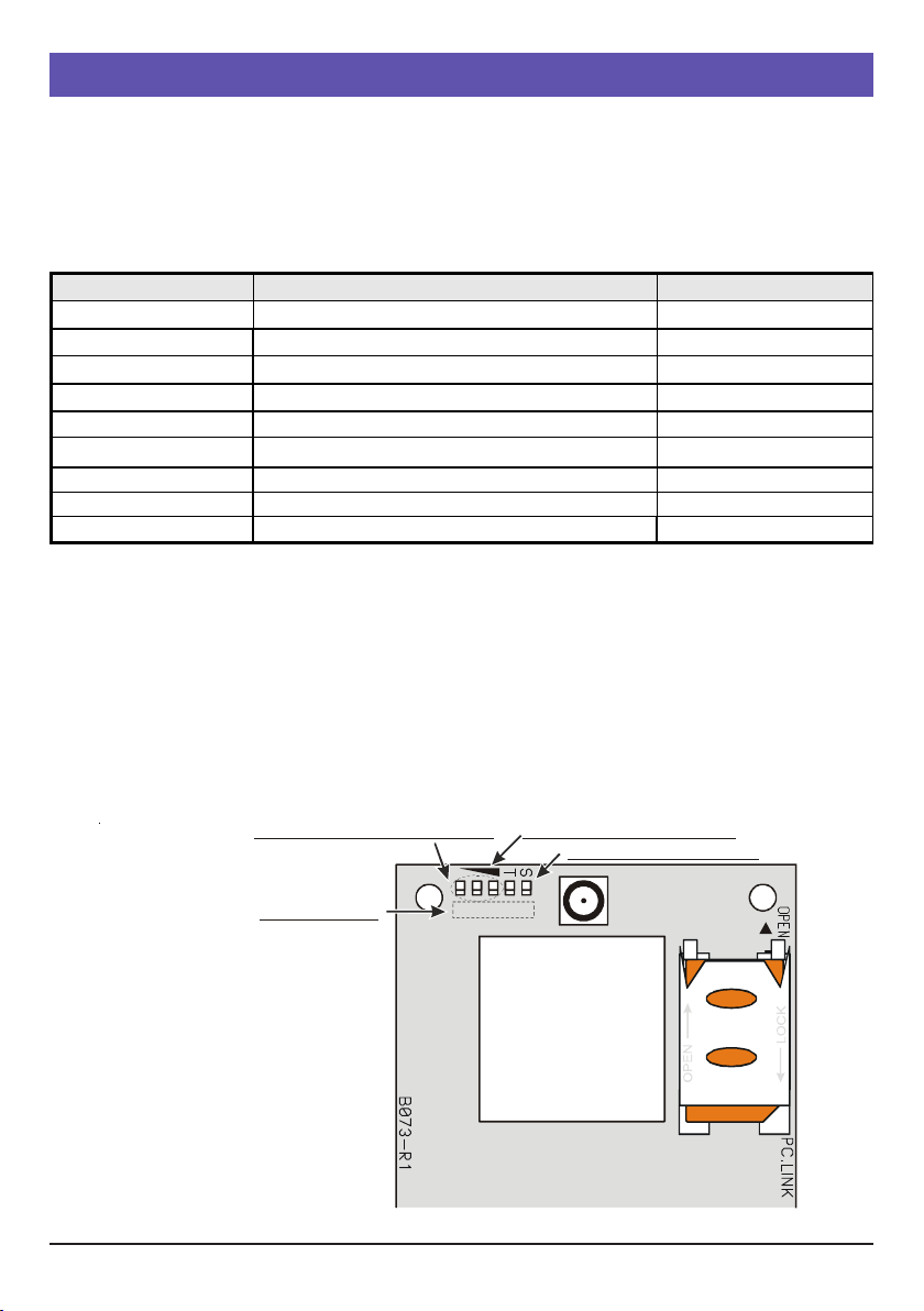
IDENTIFICATION OF PARTS ......................................... 6
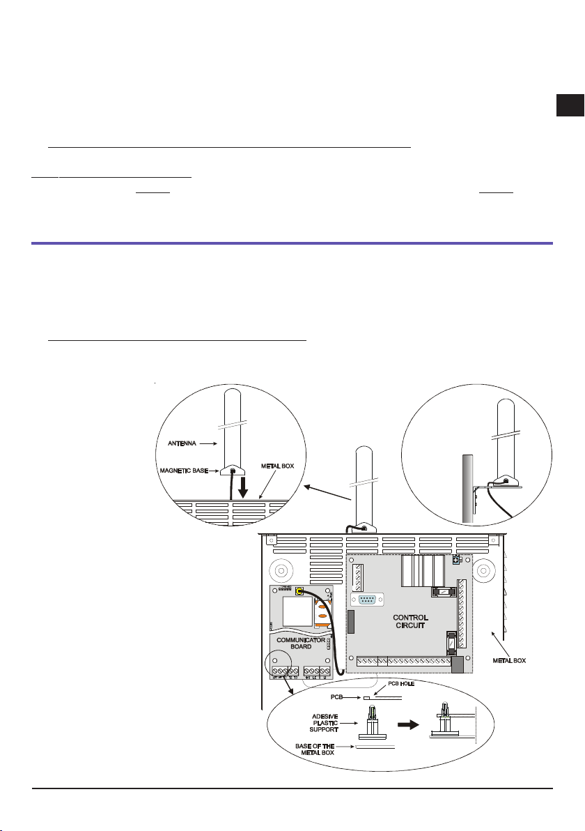
INSTALLING THE DEVICE ............................................. 6
GS3105-K or GS3125-K ......................................................... 6
GS3105-BA, GS3125-BA or GS3100-BX .............................. 7
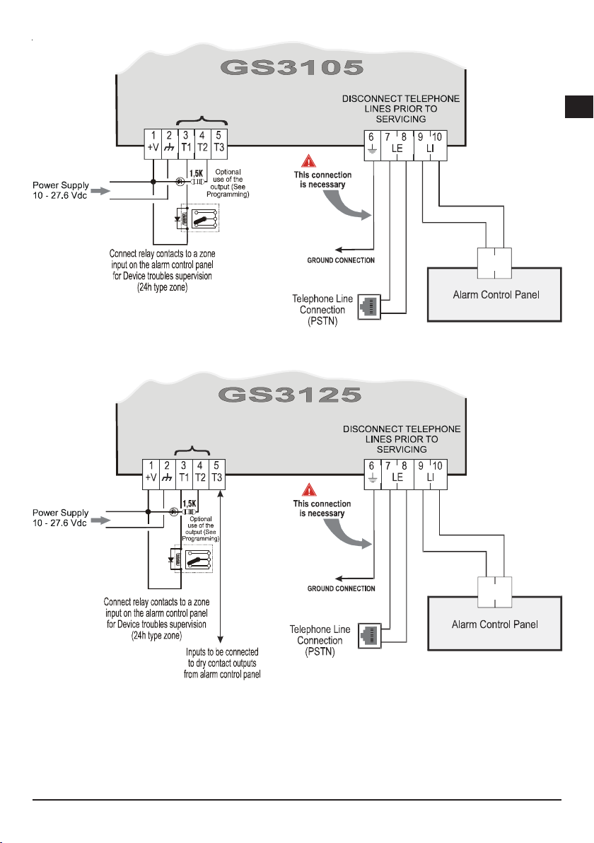
CONNECTING THE DEVICE ........................................... 8
STATUS LEDS ............................................................... 10
OPERATING PRINCIPLES ............................................ 11
Restore default programming .................................................. 11
PSTN pre-set channel ............................................................ 11
GSM pre-set channel ............................................................. 11
Contact ID transmission sequence on GPRS ........................ 11
SMS dialer (GS-3120 series only) ......................................... 12
Voice dialer (GS-3120 series only) ......................................... 12
Priority management (GS3125 series only) ...........................13
Simulated telephone line priority ................................................... 13
SMS dialer priority ........................................................................... 13
Dialer event priority ........................................................................ 13
Pay As You Go Balance (GS3125 series only) ..................... 14
(PTM) monitoring of communication with the control unit .........14
ACTIVATING THE OUTPUTS ......................................... 14
Activating/DeactivatingAutomatic Outputs .............................. 14
Remote Activation and Deactivation of the Outputs ................. 14
GS3105 ........................................................................................... 14
GS3125 ........................................................................................... 14
Bistable outputs (GS3125 only) ..................................................... 15
Monostable Outputs ........................................................................ 15
SMS (GS3125 only) ......................................................................... 15
Caller Identification ......................................................................... 15
REMOTE PROGRAMMING (GS3125 SERIES ONLY) . 16
Changing the user code .........................................................16
Web service ........................................................................... 16
Changing the Installer code .................................................... 16
Credit balance check ..............................................................16
PROGRAMMING THE DEVICE ..................................... 16
Viewing the Device Settings ........................................................... 17
Downloading the Device Settings .................................................. 17
Preliminary operations ................................................................... 17
Phonebook .............................................................................18
Options ...................................................................................19
This page is used to set the options relating to the board. .......... 19
Dial options ..................................................................................... 19
Event priority (GS3125 series only) ............................................... 19
Codes (GS3125 series only) .......................................................... 19
Generic ............................................................................................ 19
System (GS3125 series only) ......................................................... 20
Pay As You Go (GS3125 series only) ............................................. 20
Outputs(GS3105 series only) ......................................................... 20
Primary Path .................................................................................... 20
GPRS .................................................................................... 20
Access Point Name 1 and Acces Point Name 2 ............................. 20
Main Receiver, Local Port 1 and Alarm Port 1 IP address ............ 20
Receiver 2, Local Port 2 and Alarm Port 2 IP address .................. 21
APN1 Username and Password, APN2 Username and Password . 21
Telephone numbers to decode ...................................................... 21
DNIS ................................................................................................. 21
Account code .................................................................................. 21
Enable Supervision ........................................................................ 21
Supervision time (sec) .................................................................... 21
Web Service (GS3125 series only) ............................................... 21
Status ..................................................................................... 22
Status section .................................................................................. 22
PTM ....................................................................................... 22
I/O (GS3125 series only) ......................................................22
Voice Dialer (GS3125 series only) .........................................23
Periodic voice .................................................................................. 24
Local Service Mode ........................................................................ 24
SMS dialer (GS3125 series only) ..........................................24
Periodic SMS ................................................................................... 24
Voice Message (GS3125 series only) ................................... 25
Local Voice Message Recording ................................................... 25
Local Voice Message Replaying ................................................... 25
PASS-THROUGH (GS3125 SERIES ONLY) ................ 26
Programming the Alarm Communicator .......................................... 26
Connecting the Communicator to the Power Series PC1864 panel . 26
Operations to perform on the Power Series PC1864 control panel .. 26
Operations to perform on the PC ................................................... 26
Remote programming with the DLS IV INT software .............. 27
Recycling information
DSC recommends that customers dispose of their used equipments (panels, detectors, sirens, and other devices) in an environmentally sound
manner. Potential methods include reuse of parts or whole products and recycling of products, components, and/or materials.
For specific information see: www.dsc.com
Waste Electrical and Electronic Equipment (WEEE) Directive
In the European Union, this label indicates that this product should NOT be disposed of with household waste. It should be deposited at an
appropriate facility to enable recovery and recycling.
For specific information see: www.dsc.com
Hereby, DSC (Digital Security Controls) declares that the
GS3105 and GS3125 series
is in compliance with the essential requirements and other relevant provisions of Directive 1999/5/EC. The complete R&TTE Declaration of
Conformity for each Device can be found at www.dsc.com
Installation of these systems must be carried out strictly in accordance with the instructions described in this manual, and in compliance with
the local laws and bylaws in force. The above mentioned GS3105 and GS3125 series have been designed and made to the highest standards of
quality and performance. The manufacturer recommends that the installed system should be completely tested at least once a month.
DSC shall not be responsible for damage arising from improper installation or maintenance by unauthorized personnel.
DSC reserves the right to change the technical specifications of this product without prior notice.

GS3125/GS3105 5
GG
GG
G
INTRODUCTION
Devices in the GS3105 and GS3125 series are GSM communicators which, in the absence of a PSTN line, transmit vocal or digital alarms
to System III or System II receivers, via GPRS. You can have the following items for each series:
— The GS3105-K and GS3125-K kits, including GSM/GPRS communicator, antenna with cable from 2 meters, metal bracket and
PCLINK-PCLINK cable;
— The GS3105-BAand GS3125-BAkits, including GSM/GPRS communicator, antenna with 25 cm wire, casing and PCLINK-PCLINK cable.
— The GS3100-BX kits, including antenna with 25 cm wire and casing.
All information relating to a specific version shall be attested to by reference to the the corresponding code. The word “Communicator” is
being used to describe functions which are common to the various versions.
This manual provides programming and operation of the GSM/GPRS alarm Communicator. If there are any special installation require-
ments, the remote ANT-EU outdoor antenna may be used.
This Device is fixed and shall be installed by Service Persons only (service person is defined as a person having the
appropriate technical training and experience necessary to be aware of hazards to which that person may be exposed
in performing a task and of measures to minimize the risks to that person or other persons). It shall be installed and
used within an environment that provides the pollution degree max 2, over voltages category II, in non-hazardous,
indoor locations only. This manual shall be used with the Installation Manual of the alarm control panel. All instruc-
tions specified within that manual must be observed.
Features
Models GS3105-K, GS3125-K GS3105-BA, GS3125-BA
Input Voltage between 10 and 27.6 V_
Standby current 100 mA maximum (not including the outputs) at 13.8 Vdc
Maximum alarm (Transmitting) current 200 mAaverage (not including the outputs) at 13.8 Vdc
Outputs 3 open collector, 100 mA
Operating frequency 900/1800 MHz or 850/1900 MHz
Maximum loop resistance of line between
the device connected in series on LI 1 Kohm
Maximum number of parallel devices
connected on LI 2
Operating Temperature 5 to 40 °C / 41 to 104 °F
Dimensions (WxHxD) 60.5x142x15.3 mm
(PCB only)
90x190x75 mm
(without antenna)
Weight 66 g 348 g
Simulates land line
Switches automatically to GSM Network in the event land line
trouble (line down)
Manages and signals Incoming/Outgoing calls
GSM signal indicator
3 programmable terminals as Open Collector Outputs or Input
Lines (GS3125 series only)
Land line overvoltage protection
GSM Quad-Band
Antenna with magnetic base
SMS dialer (GS3125 series only)
Voice dialer (GS3125 series only)
Supports Contact ID communication format from a connected
control panel for communication over the GPRS network
GPRS/Internet communication with receivers Sur-Gard Sys-
tem III / II
PC-programmable options
Pass-through function for connecting up to a DSC Power
Series PC1864 control panel (GS3125 series only).
11 SMS messages, each with a maximum length of 100 char-
acters (2 for each Input Line plus 4 for Status Indications and
1 Periodic), GS3125 series only
8 telephone numbers (max. 16 digits) programmable for the
SMS dialer (GS3125 series only)
4 phonenumbers programmable for Contact IDDialeronGPRS
Up to 100 telephone numbers (max.16 digits) program-
mable for the remote activation of the OC output
Remoteactivationoftheoutputsthroughcalleridentificationand/or
SMStransmission(SMStransmissionfortheGS3125seriesonly)
Credit balance check for pre-paid SIM CARDS (GS3125
series only)
(PTM) monitoring of communication with the control unit
Technical Specifications
The input voltage to this Communicator can be drawn from the Control Panel or provided by an external power supply (not supplied).

6GSM/GPRSAlarm Communicators
Description
This Communicator manages SMS and Central Station transmissions (SMS transmission for the GS3125 series only) and can
simulate the land line in the event of trouble (land line down) or even substitute the land line completely in areas where the GSM service
is provided and where the land line is not available. Has capability of communicating alarm signals via the GPRS data network. This
capability enables a fast reliable path to central stations equipped with a Sur-Gard System III or System II receiver. The performance
of this Communicator depends greatly on GSM Network coverage, therefore, it should not be mounted without first performing
placement tests of the antenna to determine the best location for reception (at least 1 green LED should remain lit).
The GS3105 Communicators series have 3 Outputs, one of which may be activated/deactivated remotely, while the other 2 may be
used to indicate: problems on the PSTN telephone line; problems on the GSM network.
The GS3125 Communicators series, on the other hand, have 3 terminals which can be programmed as follows:
– Outputs (default setting) which can be activated/deactivated remotely, or used to provide status indications (problems on the PSTN
telephone line; problems on the GSM network; Supervision Message Missing; Fail To Comunicate).
– Input lines for speech dialer and SMS dialer activation; these functions can also be used to transmit status indications.
Due to the characteristics of GSM Networks, this Communicator can activate only as intended and cannot be used as a modem for fax/
data transmissions or for teleservice operations.
IDENTIFICATION OF PARTS
The numbers in square brackets []in this manual refer to the main parts of this Communicator (see Fig. 1) described in this section.
INSTALLING THE DEVICE
Do not route any wiring over circuit boards.
This Communicator shall be installed by qualified SERVICE PERSONS only, in the shelter of a safe and dry site, away
from radio-transmitting equipment.
Test the GSM Network reception before mounting this Communicator in the proposed placement.
GS3105-K or GS3125-K
This Communicator consists of a board intended to be placed inside the intrusion panel, preferably having a metal
box, and of an antenna that is connected to the board by a coaxial cable. During normal working, those elements
(board, antenna and cable) could generate radiated electromagnetic fields and, if there are any electronic devices not
sufficiently immune to such fields nearby, there might occur certain unwanted interactions. For this reason it is
advised to place the board as far away as possible from such susceptible devices and to put the antenna on the
external surface of the metal box or far away from it by means of the bracket. It is advised to keep inside of the panel
metal box the minimum coaxial cable part and to place any extra length on the outside of the metal box.
1. Loosen the screws and remove the control panel cover.
2. Establish an area inside the metal casing which can be used to hold the board, including the wiring.
3. Position the 4 adhesive plastic supports [14] on the base of the metal casing, then fit the holes [7] on the Electronic board into the
adhesive plastic supports, as illustrated in Figure 2.
4. Fit the antenna [1] to the outside of the casing.
4a. Position the antenna [1] on top of the metal casing (Fig. 2) so that the magnetic base [2] sticks to the surface. Feed the antenna cable
through the cable feed opening in the metal casing. If necessary it is possible to use the metal bracket [13], (Fig.2a).
Fix the metal bracket [13] to a suitable support using the holes provided [12]. Position the antenna [1] on top of the metal casing - see
Fig. 2a - so that the magnetic base [2] sticks to the surface. Feed the antenna cable through the hole [11] in the metal bracket [13].
5. Connect the wire [3] to the GSM antenna connector [4].
6. Complete the connections on the terminal blocks [10].
7. Following the arrow, insert the SIM-CARD [8] face down in the SIM holder [6] (see Figure 1).
!!
!!
!The SIM-CARD PIN must be disabled before the card is inserted into the transmitter.
8. Makesurethatall the green LEDs flash when the productisswitchedon;thismeanstheCommunicatoris in its initialisation phase.

GS3125/GS3105 7
GG
GG
G
Fig. 2 - Fitting the Communicator board inside the control panel.
9. Checking Signal Strenght :
–make sure that at least one of the green LEDs remains lit; all green LEDs lit indicates optimal coverage;
– if the green LEDs are not illuminated, the signal strength is TOO WEAK; change the position of the antenna until you find a position
which offers acceptable signal strength, at least one LED illuminated.
10. Close the control panel cover.
Connect power circuit only after the cabinet has been secured to the building or structure and has been connected
to the protective earth ground of the building.
!!
!!
!Before inserting or removing the SIM card, please ensure the unit is powered down.
ANT-EU Remote antenna
For details of how to fit the ANT-EU remote antenna, please refer to the instructions supplied with the product. The ANT-EU is used to
provide the Communicator a excellent GSM signal strength.
GS3105-BA, GS3125-BA or GS3100-BX
See figure 1.
1. Mark the position of the holes [19] required to fix the metal base [17] to the wall.
2. Drill holes in the wall as marked.
3. Insert the 4 P.C.B. supports [16] into the holes on the metal base [27].
4. Feed the connection cables through the opening on the base [22].
5. Fix the metal base to the wall using wall anchors (not supplied).
!!
!!
!Make sure you do not damage wiring or pipes in the chase.
6. Position the electronic P.C.B. (not supplied with the GS3100-BX) on the supports [16] and push it down until it clicks into position, as
illustrated in Figure 1.
51
96
a)

8GSM/GPRSAlarm Communicators
7. Connect the antenna wire [3] to the connector on the electronic P.C.B. [4].
8. Feed the antenna wire [3] the cable clamp tab [26], then through the opening [23].
9. Position the antenna [1] on the upper edge of the base so that the magnetic base [2] adheres to the surface.
The antenna may be positioned on the top edge of the base, at the point most suited to receiving the GSM signal.
10. If necessary, fit the MAXIASNC anti-tamper switch [15] (opzional) to the pins as illustrated in Figure 1.
The switch lever must be directed as illustrated in Figure 1, otherwise the device will not work correctly.
11. Perform the terminal block connections [10] as described in par. “Connecting the device” and, if necessary, connect the anti-tamper
switch.
The anti-tamper switch should be connected to the anti-tamper line or a relevant zone of the control unit. Please refer
to the control unit instructions for further information.
12. Following the arrow, insert the SIM-CARD [8] face down in the SIM holder [6] (see Figure 1).
!!
!!
!The SIM-CARD PIN must be disabled before the card is inserted into the transmitter.
13. Makesurethatall the green LEDs flash when the productisswitchedon;thismeanstheCommunicatoris in its initialisation phase.
14. Checking Signal Strenght :
–make sure that at least one of the green LEDs remains lit; all green LEDs lit indicates optimal coverage;
– if the green LEDs are not illuminated, the signal strength is TOO WEAK; for the signal to be of an acceptable level, at least one green
LED must be lit.
15. Close the communicator: fasten the lower side of the cover [18] to the base [17] then press the upper edge of the base to close the
cover; fix the cover in place using screws [25].
Connect power circuit and the telephone line only after the cabinet has been secured to the building or structure and
has been connected to the protective earth ground of the building.
!!
!!
!Before inserting or removing the SIM card, please ensure the unit is powered down.
CONNECTING THE DEVICE
This section describes the various terminals. Figure 3 shows a typical wiring diagram.
!!
!!
!The Open Collector current may not exceed 100 mA. If necessary, commutate greater loads using switches.
No. Term in als Model
GS3105-K, GS3105-BA GS3125-K, GS3125-BA
1+V
Power supplied by the control unit or by the external power supply (optional), at a level between 10 and 27.6 Vdc,
make sure that this is protected and operating at a limited current; Limited Power Source (LPS) in conformity with
EN 60950-1:2006 standard.
!To connect the supply use wires with a maximum 2 mt length and 0.75mm² cross-section. For shorter wires
use suitable cross-sections.
2MNegative: Power supply and shared teminal for the Open Collector outputs.
3T1
Open Collector outputs: These outputs are activated by
breakdown events on the PSTN line or on the GSM
network.
Programmable terminals: These terminals can be
programmed as;
– Open collector outputs (default setting): These outputs
may be activated either by programmed events (automatic
activation), or by a command sent via SMS, or through
caller recognition (remote activation); please refer to the
“Output activation” section for further information. The
maximum current available at each OC output is 100 mA.
– Input lines:When these inputs receive alarm signals, they
can activate the SMS and telephone dialer functions (please
refer to the “SMS dialer” and “Voice dialer” sections).
4T2
5T3
Programmable Open Collector output: This output may
be activated by a caller identification event. The maximum
current sink of each OC Output must not exceed 100 mA.
6-Earth Ground:This terminal must be connected to the Mains Earth, in order to comply with the Telecommunications
Network Safety Standards (Overvoltage Protection Requirements).
7LE External telephone line: These terminals can be connected to the land line.
8
9LI Internal telephone line: These terminals must be connected to the control panel or an alternative communication terminal.
10

GS3125/GS3105 9
GG
GG
G
Fig. 3 - GS3105 and GS3125 wiring diagram
Open Collector Outputs
RJ-11
RJ-11
Relè
RM-1
Relè
RM-1
T
I
P
R
I
N
G
T
I
P
R
I
N
G
Example of the T1 and T2
programmed as
Open Collector Outputs
terminals
Termi nal T3
programmed
as Input Line
WARNING
Incorrect connections may result in FTC fault or improper operation. Inspect wiring and ensure connections are correct before applying power.
DO NOT route any wiring over circuit boards; maintain at least 1” (24.5 mm) separation. A minimum 1/4” (6.4 mm) separation must be
maintained at all points between Power Limited wiring and all other Non-Power Limited wiring.

10 GSM/GPRSAlarm Communicators
STATUS LEDS
There are 5 LEDs on the PCB (see Figure 4): three green LEDs (L1, L2 and L3), one yellow LED (L4) and one red LED (L5). These
indicate the connection, transmission, malfunction conditions and, for the GS3125 series only, the Communicator status (see table 2).
During initialisation and the programming phase, the LEDs flash.
RED — This LED is normally OFF. It indicates malfunctioning by flashingin the event of trouble. On power-up, this Device will check for
certain trouble conditions to be met in the order listed below. The most significant malfunctioning status will be indicated, with the
corresponding number of flashes of the RED LED (L5), (see below for number of flashes and malfunctioning indication priority).
Indication priority Type of malfunction Red LED flashes
1 (HIGH) Firmware problem (incorrect firmware) 1
2Power supply problem 2
3GSM module problem 3
4SIM problem 4
5GSM reception problem 5
6GPRS problem 6
7Receiver not available 7
8(LOW) Monitoring receiver not detected (receiver 1) 8
No Troubles Off
YELLOW — This LED will switch ON when the interface switches to the GSM Network (due to land line trouble or the lack of this line). If
it flashes slowly, it indicates that a call is taking place on the GSM network (both incoming and outgoing). If lit steadily along with the red
LED, this indicates that the default manufacturer data is loading.
GREEN — The three green LEDs (L1, L2 e L3) indicate the GSM signal strength and status (Table 2), as illustrated in Figure 4:
The first LED (L1) near the fixing hole. If this LED is OFF, the GSM Network service is unavailable (NO SERVICE).If only this LED
is ON, the GSM Network recepetion is weak but sufficient to manage all telephone communications.
ThesecondLED (L2). When this LED is ON, the reception isgood.ThisLEDwillswitchONonlywhenthefirstGREEN LED is ON.
The third LED (L3). When this LED is ON, indicates excellent GSM signal strength; it only illuminates when the first and second LEDs
are already ON.
Fig. 4 - Operation indicator LEDs
GSM reception level symbol
Operation indicator LEDs
LEDs Indicating GSM reception
LED numbering
(numbering not present on the
electronic board). This numbering
has only been provided in order
to make identifying each LED
easier within the document.
12345

GS3125/GS3105 11
GG
GG
G
OPERATING PRINCIPLES
This Communicator offers the option of selecting the “Primary Path” for communication purposes. Will provide the line ring voltage for
incoming calls and will decode DTMF dialling. The Simulated land line provides the alarm control panel or an alternative communication
terminal, with a backup line in the event of PSTN line trouble. Commutation between PSTN and GSM, does NOT occur during ongoing
calls. The Operating priority (selected during programming) determines how this Communicator manages communication (SMS and voice
for the GS3125 only series), as well as calls from telephone devices connected to the LI terminals (such as a burglar alarm control panel).
This Communicator is unable to decode Pulse dialling.
To prevent any unwanted use of a simulated line via GSM, the equipment gives out a signal in the form of a double beep
during vocal calls. The first double beep is produced after 5 minutes and the following ones at 30 second intervals each.
Restore default programming
To restore the default programming of the transmitter, proceed as follows:
1. Disconnect the transmitter from the power supply.
2. Keep terminals 1 and 4 on connector [9] (fig. 5, page 17) short-circuited, using clamps for example, and restore the power supply.
3. The 5 LEDs (L1, L2, L3, L4 and L5) will light up briefly (less than 1 second).
4. As soon as the short circuit is detected, the 3 green LEDs (L1, L2, L3) switch off, while the yellow and red LEDs (L4, L5) remain
illuminated (for a few seconds) to indicate that default programming is being restored.
5. When the yellow and red LEDs (L4, L5) light up, remove the short circuit between terminals 1 and 4 on connector [9] (fig. 5, page 17).
6. Once this procedure is complete, the 3 green LEDs flash to indicate that the transmitter is initialising.
Recorded voice messages are NOT deleted when the default settings are restored.
PSTN pre-set channel
If the voltage on the land line terminals (LE) drops below 3 Vdc for a period of between 10 to 3600 seconds (programmable value),
this Device will switch the connected telephone device (connected to the LI terminals) to the GSM Network. When the PSTN telephone
line is restored, it commutates once again, after a programmed period of time, to the PSTN telephone line.
GSM pre-set channel
This provides the devices connected to the LI terminals with a simulated line if GSM reception is detected. If there is no GSM reception, it
commutates to the PSTN telephone line.
Contact ID transmission sequence on GPRS
The Communicator, if telephone numbers have been entered on the page GPRS->Telephone numbers to decode for decoding using
the GS3125/GS3105 Console software, directs calls to these numbers over the GPRS line.
When an event is triggered, theAlarm Panel goes off-hook.
The Communicator will assert dial tone.
Control Panel dials the number of the central station. Ensure the alarm panel inserts a minimum 1-second pause, or has dial tone
search enabled before dialing the number.
The Communicator will send the required Contact ID dual tone handshake.
After receiving the handshake, panel transmits alarm message in DTMF format.
The Communicator decodes and transformsDTMF digits into the packet and sends it to theCentral Station Receiver over the GPRS network.
The receiver acknowledges the event and sends the command to this Communicator, which generates the corresponding kiss-off
signal (at a frequency of 1400 Hz) and sends it to the control panel.
After the Communicator generates kiss-off, the panel goes on-hook if no more alarms need to be sent, or it can send the next alarm.
Table 2 - GS3125
Communicator status
indications provided by the
flashing of the green LEDs
(L1, L2, L3).
Green LED flashes Meaning of indication
L1 Voice message transmission in progress
L3 Remote Session; will flash until you exit the GPRS remote session
(Web service).
L1+L2 Service mode; flashing continues until the device exits this mode
L1+L3 Incoming SMS message; will flash for 5 seconds.
L1+L2+L3 The Communicator is initialising; flashing continues until a GSM
signal is found

12 GSM/GPRSAlarm Communicators
SMS dialer (GS-3120 series only)
In SMS dialer operating mode, one or more telephone numbers (the first 8 entries in the phonebook) are sent SMS messages (as
programmed previously) corresponding to the following events (see table below):
No. Event description
Programmed telephone numbers
(first 8 entries in the phonebook) SMS message
12345678
1 Input 1 Event *SMS string
2 Input 1 Restore *SMS string
3 Input 2 Event *SMS string
4 Input 2 Restore *SMS string
5 Input 3 Event *SMS string
6 Input 3 Restore *SMS string
7PSTNFaultEvent
8PSTNFaultRestore *SMS string
9 Mains Fault Event
10 Mains Fault Restore *SMS string
11 Periodic SMS *SMS string
Event disabled on telephone number
Event enabled on telephone number
* The SMS string may be up to 100 characters long
Alarm indications which may occur on one or more of the 3 programmable input lines. Bear in mind that 2 SMS messages can be
programmed for each of the 3 input lines on the device, one forActivation and one for Resetting.
PSTN line test. 2 SMS messages may be programmed: one for PSTN line absence and one for Resetting.
Power supply voltage test. 2 SMS messages may be programmed: one indicating Power supply voltage problems and one for
Resetting.
Periodic SMS message, with a programmable time period between 1 hour and 1 year.
An SMS message is transmitted when one of the above events occurs, for which an SMS message and at least one
telephone number has been programmed.
Voice dialer (GS-3120 series only)
During operation in Voice dialer mode, one or more telephone numbers (the first 8 entries in the phonebook) are sent a pre-recorded voice
message. Up to 8 messages may be recorded, each with a maximum duration of 16 seconds. Each message is recorded onto a solid state
memory, thereby eliminating all problems linkedto the useof magnetictape, such asthe deterioration ofmessage qualityover time; the jamming
of mechanical systems after extended periods of inactivity, etc. The messages are linked to the following events (see table below):
No. Event description
Programmed telephone numbers
(first 8 entries in the phonebook)) Mess. #1 Mess. #2 Mess. #3
12345678
1 Input 1 Event
2 Input 1 Restore Voice
Message 1
Voice
Message 2
3 Input 2 Event
4 Input 2 Restore Voice
Message 2
5 Input 3 Event
6 Input 3 Restore
7 PSTN Fault Event
8 PSTN Fault Restore
9 Mains Fault Event
10 Mains Fault Restore
11 Periodic Call
Event disabled on telephone number
Event enabled on telephone number

GS3125/GS3105 13
GG
GG
G
Alarm indications which may occur on one or more of the 3 programmable input lines. Bear in mind that 2 voice messages can be
recorded for each of the 3 input lines on the device, one forActivation and one for Resetting.
PSTN line test. 2 voice messages may be recorded: one for PSTN line absence and one for Resetting.
Power supply voltage test. 2 voice messages may be programmed: one indicating Power supply voltage problems and one for
Resetting.
Periodic voice message, with a programmable time period between 1 hour and 1 year.
A voice call takes place when an event occurs on a channel for which a voice message and at least one telephone number has been
programmed.
In this case, the Communicator performs the following steps:
1. The Communicator selects a telephone number and forwards the call over the GSM telephone line.
2. The Communicator makes sure that the number is not busy and that there are no problems on the GSM network, so that it can proceed
with the next step, otherwise the call will end and step 1 will be attempted again, up to a maximum of 8 times (depending on the
programmed value).After 8 attempts the call cycle will be considered complete. If the alarm channel has been programmed to call
several telephone numbers, they will be called in a set sequence. By doing this, for example, the possibility of calling a busy number
several times in the space of a few seconds can be avoided.
3. The Communicator waits for a response from the number called for a period of up to 60 seconds. If the outcome is positive, the
Communicator moves on to step 4; otherwise the call will end and step 1 will be attempted again, up to a maximum of 8 times (depending
on the programmed value).After 8 attempts the call cycle will be considered complete.
4. The Communicator reproduces the message corresponding to the channel experiencing alarm status; the call is only considered
complete once the button (if programmed) on the telephone receiving the message has been pressed. In any case, the call is
considered successful after the message has been repeated up to a maximum of 8 times (depending on the programmed value). If, at
the selection stage, several events occurred causing several different messages to be sent to the same telephone number, these
messages are reproduced (each for a maximum of 8 times, depending on the programmed value) in sequence during the same
telephone communication, thus avoiding calls being made to the same number several times. If at the end of the call cycle, the line which
caused the Communicator to be activated is still in alarm mode, the procedure described above will not be repeated again. In fact, the
line that caused a call cycle must return to standby mode before a new cycle is activated.
Priority management (GS3125 series only)
The Communicator can be used to transmit alarm events and SMS or voice messages; several priorities may be programmed using the
GS3100 Series Console software (please refer to the section corresponding to programming procedures using the GS3100 Series
Console software). The table below lists the default priority management settings.
Priority management table
Event
priority Event description Default
settings
Can be
programmed
using software
1 (HIGH) Request LI line (release) Ye s
2 Voice dialer (voice messages) Ye s
*3 (LOW) GPRS supervision No
* The GPRS supervision event has the lowest priorityand cannot be programmed using software
Simulated telephone line priority
Whenthe device connectedto the LI terminalsrequests the line, anyother call madeatthat moment inVoice dialer modewillbe terminated. The
calls requestedbythe deviceconnectedto the LI terminals(aburglar alarm control unit,for example) take placein this manner. When thedevice
connected to the LI terminals frees the line, the voice dialer will resume the suspended calls and begin sending voice messages again.
SMS dialer priority
If a piece of equipment connected to the LI terminals is making a call over the GSM network through this dialer and an SMS dialer action
needs to be performed, the call from the interface will not be terminated and the SMS message will still be sent.
Dialer event priority
The SMS messages have a lower priority than Voice messages but they can not be interrupted while they are transmitted: in this case, the
queued Voice message will be sent at the end of the SMS message sending.

14 GSM/GPRSAlarm Communicators
Pay As You Go Balance (GS3125 series only)
If the GS3100 Series Console software has been used to program the device (see Options->Pay AsYou Go), it will be possible to check
how much credit is left on the pre-paid SIM CARD. If the credit balance check feature is enabled, an SMS providing credit balance information
(supplied by the operator) is sent to the first number in the phonebook at regular intervals. In Italy the operator (TIM, Wind, Vodafone)
is recognised automatically, so the credit balance check also takes place automatically. For all other operators which support credit balance
requests via a network command, it will be possible to enter a request for information using the GS3100 Series Console software.
PLEASE NOTE - The pre-paid SIM CARD credit management service may be suspended at any time, at the discretion
of each individual GSM network operator.
(PTM) monitoring of communication with the control unit
The constant monitoring of communication with the control unit (PTM function) allows the Communicator to transmit calls via the GSM
network if communication between the alarm control unit and the surveillance control unit does not take place successfully over the PSTN
telephone line. If programmed (using the GS3100 Series Console software PTM page), this feature only works when the PSTN line is
connected to the LEterminals.
The PTM function correlates to the following Communicator alarm transmission modes:
1.Alarm on GPRS (IP communication - receiver).
2. Alarm on GSM (voice mode).
The PSTN Fault event occurs when the PTM function activates.
ACTIVATING THE OUTPUTS
The GS3105 series has the Open-Collector Outputs (the T1, T2 and T3 terminals). The GS3125 series has 3 terminals (the T1, T2 and
T3 terminals) that can be programmable as Inputs or/and Output: this terminals are programmed as Outputs by default. The Open-
Collector Outputs can be activated automatically (when certain pre-programmed events occur) or remotely, through SMS trasmission (for
the GS3125 series only) or caller identification from a number programmed previously.
Activating/Deactivating Automatic Outputs
The T1, T2 and T3 Open Collector outputs can be activated automatically by the following events:
Land line trouble (line down), (T1, GS3105 series only).
GSM Network trouble (Limited/No Service), (T2, GS3105 series only).
Supervision message missing.
Internal event communication failed (FTC).
Once an output has been activated automatically, it will not restore its state until all the causes of activation clear.
Remote Activation and Deactivation of the Outputs
CAUTION - The GSM connection must be established before the outputs can be activated/deactivated remotely.
We recommend the device is programmed with the Black list enabled (Options->Dial Options) and White list disabled
(Phonebook->White list) for the numbers you wish to use for this function.
The number used to activate the outputs via Caller Identification must be visible.
GS3105
The T1 and T2 Open Collector outputs as BISTABLE, while the T3 output is MONOSTABLE (Once a Monostable output has been
activated, it will not deactive until On Time expires).
GS3125
The Open Collector outputs can be set as Bistable (activation and deactivation takes place by means of 2 separate commands) or
Monostable (the output remains active for the ON time and returns to standby mode when this period has elapsed). Moreover,
every output can be programmed to provide a confirmation signal (an SMS programmed previously if output activation/deactivation is
performed via SMS, or a confirmation ring if output activation/deactivation is performed via caller identification).

GS3125/GS3105 15
GG
GG
G
For further information on the terms “Control string” and “User code” used in the following sections, please refer to
the “I/O” and “Options->Codes” sections of the “PROGRAMMING VIA PC” chapter.
Bistable outputs (GS3125 only)
Open collector outputs set as bistable can be activated in 2 ways:
1. By sending an SMS consisting of the User code between two #characters, the Control string (Control String can not have initial
blank spaces) and the characters “=ON#”, as follows:
#User code#String=ON# (example: #9876#HOUSELIGHT=ON#)
2. Through caller identification: in this case the output is activated at “cost-free” as the Communicator, after identifying the caller, rejects
the call and activates the output.
A bistable OC output can ONLY be deactivated by sending an SMS message consisting of the User code between two
# characters, the Control string and the characters “=OFF#”,as follows:
#User code#String=OFF# (example: #9876#HOUSELIGHT=OFF#)
The default User code is ‘0001’; if you wish to change it, please refer to the section “Remote programming->Changing the User
code”.
Monostable Outputs
OC outputs set as Monostable may be activated in 2 ways, through Caller Identification and via SMS (GS3125 only).
SMS (GS3125 only)
Send an SMS consisting of the User code between the #characters, the Control string (Control String can not have initial blank
spaces) and the characters “=ON#”,“=ON#TonU#” or “=OFF#”,as follows:
#User code#String=ON#
#User code#String=ON#TonU#
#User code#String=OFF#
The “=ON#tonU#” option is parameter allows to set the ON Time from 1 to 86400 seconds, with 1 second steps. The ON Time can be
set by means of the Communicator's console software. “Ton” is the required value and “U” is the unit in hours (H), minutes (M) and
seconds (S), as shown in the following example:
SMS Output operating mode
#9876#HOUSELIGHT=ON# Bistable Activation
#9876#HOUSELIGHT=ON#3600S# Active for 3600 seconds
#9876#HOUSELIGHT=ON#50M# Active for 50 minutes
#9876#HOUSELIGHT=ON#3600# Active as per software programming,
the set ON time does not apply
Remove the “TonU” parameter, leaving the “##” characters, to activate the output by SMS as programmed.
(example: #9876#HOUSELIGHT=ON##)
Caller Identification
Through caller identification: in this case the output is activated at “cost-free” as the Communicator, after identifying the caller, rejects the
call and activates the output.
Monostable OC outputs deactivate (switch OFF) automatically when the programmed ON Time expires.
Only the T3 output of the GS3105 can be activated through Caller Identification.
The ON time may be set to a period of time between 1 and 86400 seconds, in steps of 1 second.
The default User code is ‘0001’; if you wish to change it, please refer to the section “Remote programming->Changing the User
code”.

16 GSM/GPRSAlarm Communicators
REMOTE PROGRAMMING (GS3125 series only)
In addition to the processes described in the section Remote activation and deactivation of the outputs, it is also possible to carry
out other remote procedures through the transmission of various SMS messages.
Changing the user code
The default user code is ‘0001’; to change it, send an SMS message consisting of the characters “#CUC” followed by the old User code
and the new User code between * characters, in accordance with the following formula:
#CUC*User code*New User code*
You will receive an SMS confirmation if the User Code has been changed.
The User code may only consist of numbers from 0 to 9 (maximum 4 digits).
Web service
The Web service can be enabled using the GS3100 Series Console software (please refer to section Programming via PC->GPRS-
>Web service), or by sending an SMS message consisting of the characters “#UWS” followed by the User code and “ON” between *
characters, in accordance with the following formula:
#UWS*User code*ON*
To disable the Web service, send the following SMS message:
#UWS*User code*OFF*
Changing the Installer code
The Installer code (maximum 4 numeric characters)is used inthe event that theWeb service needsto be accessed (seesection Programming
via PC->Codes->Installer code). The default istaller code is ‘0002’; to change it, send an SMS message consisting of the characters “#CIC”
followed by the old Installer code and the new Installer code between * characters, in accordance with the following formula:
#CIC*Installer code*New installer code*
You will receive an SMS confirmation if the Installer Code has been changed.
The Installer code may only consist of numbers from 0 to 9 (maximum 4 digits).
Credit balance check
To find out the credit balance via SMS, you can either use the GS3100 Series Console software (see section Programming via PC-
>Options->Pay As You Go), or you can find out remotely by sending an SMS message consisting of the characters “#CCC” followed
by the * character, in accordance with the following formula:
#CCC*
The balance SMS will be sent to the Telephone Number #1 of the Phonebook.
The pre-paid SIM CARD credit management service may be suspended at any time, at the discretion of each individual
GSM network operator.
PROGRAMMING THE DEVICE
For proper function of this Device, use a 32 K SIM CARD (or higher).
For programming, the PC-Link cable (not supplied) must be connected to the Connector [9] of the Communicator and a COM port on the
PC (see Fig. 5); the GS3100 Series Console application is also required. The PC-Link cable shown in Figure 5a, or the PC-Link cable
shown in Figure 5b, can be used for the connection. Make sure you insert the PC-Link cable connector in the right way. Once the PC-Link
cable has been connected, set the computer COM port through the Options->Serial ports. Check the serial link and the serial port
settings in case of communication problem, or use a different USB-RS232 adapter.
To install and run the GS3100 Series Console application, you will need to log on to the PC as the Administrator; we
also recommend to verify the firewall’s options if problems arise while the application is being installed.

GS3125/GS3105 17
GG
GG
G
Viewing the Device Settings
To view the Communicator settings on the screen, use the Upload from board icon .
Downloading the Device Settings
Once programming has been completed (or an uploaded file containing existing data has been modified), download the data into the
Communicator, using the Download to board icon .
Preliminary operations
When the application starts, you will be presented with the Main window: if you use the mouse to click the menu option Untitled #1 in the top
left-hand part, two sections appear.
The following sections may be found within the general parameters section:
Customer informations: This section can be used to set the Communicator series (GS3105 or GS3125), or to recall and
update the configuration corresponding to a particular client as follows:
1. Left-click on the application.
2. Enter or update the information relating to the customer and the system. Click to confirm .
Upload from board: If this icon is selected, the data programmed on the board is loaded onto the PC.
Download to board: If this icon is selected, the programmed data is sent to the board.
Factory defaults: Select this icon to restore the default settings. It should be noted that restoring the default settings
does not delete any voice messages recorded.
Board reset: If this icon is selected, the Communicator is reset.
The section shared by the GS3105 and GS3125 series includes the following pages
Phonebook: Telephone contact list page.
Options: Options page.
GPRS: GPRS parameters page.
Fig. 5 - Diagram of the PC-Link connection cable
5
2
3
RS-232
ab
Makesure you insert the PC-Link
cable connector in the right way Make sure you insert the PC-Link
cable connector in the right way
14 14

18 GSM/GPRSAlarm Communicators
Status: Page used to check the status of the Communicator.
PTM: PTM function setup page.
The following pages only apply to the GS3125 Communicator series.
I/O: Communicator output/input parameter programming page.
Voice Dialer: Page used to set all parameters relating to the voice dialer.
SMS Dialer: Page is used to program all SMS dialer options.
Voice Message: Page used to manage voice messages.
To start the configuration of a new Customer, click on File->New.
To display the list of customers stored in the archive, select the menu command File->Open. This section will allow you to delete or retrieve
configuration data, as follows:
1. Using the right button on the mouse, click on the Customer’s name.
2. Click Load upload the respective data from the Hard-Disk, or Delete selected customer to delete the data
configuration.
You can load the configuration data by double clicking the respective name field. You can list Customers in alphabetical or code order
by clicking the heading of the column concerned. The configuration data are grouped in the following pages. The (Status) page is
for “Supervisory and Control” purposes.All the pages are described in detail in this section.
Phonebook
The Telephone Page phonebook holds 100 telephone numbers.
The Pay As You Go Balance is sent to the Telephone Number #1.
Description:Enter an alphanumeric string of up to 16 characters.
Telephone number:Enter a telephone number of up to 16 digits, preceded by the correct international prefix in the format "+xxx"
(only digits and “+” signs are accepted).
Activates Output:Select the telephone numbers which can activate the outputs T1 (OC1), T2 (OC2) and T3 (OC3) when the
Communicator receives a call from them. This function does not depend on the White List or Black List options (Options page->Dial
options).The Calling Line Identifier service must be enabled before the output can be activated.
In the GS3105 series, it is possible to only activate the T3 output (OC3).
To activate the output in the GS3125 series, programme the T1 (OC1), T2 (OC2) and T3 (OC3) terminals as
“Output” and enable “Reserved Output” (see pages referring to I/O->Type and I/O->Reserved Output).
Ouput Activation Confirmation: this option is only available for the GS3125 series; tick this box to receive a confirmation ring once
the output has been activated.
CAUTION:
—the ring will be received 1 minute after the output has been activated;
—if the transmitter is already in operation (for example: the GSM channel is busy with a voice communication), the
confirmation ring will not take place;
—the option “Ouput Activation Confirmation” cancels the incoming call after approximately 5 s, even if the “Black
list” option is not enabled.
White List: Enable
or disable
the White List area would allow the Communicator to accept or refuse incoming calls. The
functioning mode of the White List option is linked to the
selection or non-selection
of the Black List, area which is present on
the inside of the Options page->Dial options, as seen in the following table:
White List Black List Functioning mode
Accept incoming calls from any number
Refuse any incoming call
Accept incoming calls only from numbers having an enabled
White List option, refuse call coming from all other numbers

GS3125/GS3105 19
GG
GG
G
Options
This page is used to set the options relating to the board.
Dial options
This part is used to enter some of the characteristics relating to the telephone numbers used.
Prefix:This Device will prefix the digits entered in this field to all the telephone numbers dialled through the GSM Interface function.
If necessary enter a Prefix (maximum 8 digits) in this field. If no Prefix is required, leave this field empty.
Digits to Remove: If this Communicator is connected downstream to a switchboard, the telephone numbers (programmed on the Control
panel)must be preceded bytheswitchboardnumber (normally one digit).As the switchboard numberisnot required when calls aresent over
theGSM Network, itmustbe removed from thedigitswhich form thetelephonenumber. Enter the numberofdigits that form theswitchboard
number (e.g. if switchboard number is 01, enter 2 in the “Digits to remove” field, as 2 numbers form the switchboard number).
The telephone number should at least have two digits more that the number in the “Digits to remove” area, otherwise
the engaged tone will be come through, e.g.:
—the dialled telephone number is 0123, with 2 digits to be removed = correct, the remaining number to be inserted is 23.
—the dialled telephone number is 123, with 2 digits to be removed = engaged tone, the remaining number to be
inserted is 3.
Enable Black List:Check this box if you do not wish to receive calls from telephone numbers, authorising only the numbers selected
previously using the White List function (Phonebook page->White List).
Only the “Black List” option cancels the call immediately.
When the “Black List” and “Activates Output” options are enabled, there is a delay (some seconds) before the call is
cancelled;
When the Ring is selected for the Activation Confirmation option, there is a delay (some seconds) before the call is
cancelled;
The output will be not activated when the call is canceled.
Event priority (GS3125 series only)
This page may be used to program several Communicator priorities, for the transmission of alarm events (see Priority management
section).
Off-Hook:This box can be used to establish the priority of telephone devices connected to the LI terminals (such as a burglar alarm
control panel). It is enabled
by default; to disable it remove the tick
.
Voice Dialer:This box can be used to establish Voice dialer (voice message) priority. It is disabled
by default; to enable it, mark
it with a tick
.
Codes (GS3125 series only)
User Code:Enter the account code in this box (maximum 4 numeric characters) to activate outputs remotely. For further information,
please refer to the section “Activating the Outputs->Remote Activation and Deactivation of the Outputs”: The default code
is set to ‘0001’.
Installer Code:The Installer code can be entered in this field (maximum 4 numerical characters). This code allows access to the
“Web Service” interface when required. The default code is set to ‘0002’.
Generic
This section may be used to set the audio levels of the loudspeaker and microphone fitted to the GSM transmitter.
Speaker volume:The volume of the loudspeaker may be adjusted by shifting the cursor.
Microphone volume:The volume of the microphone may be adjusted by shifting the cursor.
CAUTION: a high microphone volume may corrupt the DTFM signals, making them unrecognisable to the devices
connected to the LI terminals.
Tones...:Select the name of Communicator's country of installation: the selected country will establish a series of parameters for the
proper working of the simulated telephone call.
LE failure timeout :Enter the time in seconds (between 10 and 3600 seconds) for the Line down on the LE terminals, before the
PSTN Fault event occurs.
The time may increase up to 60 seconds if some telephone devices are connected to the terminals LI.
LE restore timeout:Enter the time in seconds (between 30 and 3600 seconds) that the telephone line must be present on the LE
terminals before the PSTN Fault event restores.

20 GSM/GPRSAlarm Communicators
System (GS3125 series only)
This section refers to the System.
SIM Phone Number: Enter the telephone number of the Communicator’s SIM CARD (maximum 16 digits).
Auto Clock Adjusting: Checking this option the device will update the system date and time by sending an SMS itself.
SMS Service Center Address: This is a read-only option. It shows the number of the SMS services centre on the SIM CARD.
Pay As You Go (GS3125 series only)
The pre-paid SIM CARD credit management service may be suspended at any time, at the discretion of each individual
GSM network operator.
This section can be used to send an SMS providing credit balance information (supplied by the operator) to the first number in the
phonebook at regular intervals. Program the following options for a correct credit balance check request, in accordance with the type of
operator used:
Enquiry Type: selection of enquiry type (SMS, Call, Service Command).
EnquiryNumber:telephonenumbertocallortowhichanSMSmessageshouldbesent in order to request credit balance information.
Balance Message: string used to send SMS messages and to make requests via service commands.
Example for Italian operators
Options Vodafone Wind TIM
Enquiry Type Call Service Command SMS
Enquiry Number 404 40916
Balance Message *123# PRE CRE SIN
Interval: Enter the interval (HH-DD) at which you wish to send a perodic SMS containing credit balance information (if supported by
your telephone operator). The interval consists of the following values:
— (HH) next message time - Select the time at which you wish to send the next periodic SMS. The interval for these values may be
set between 0 and 23.
—- (DD) next message day - Select the day on which you wish to send the next periodic SMS. The interval for these values may be
set between 0 and 365.
Outputs(GS3105 series only)
This section may be used to set the operating modes of the outputs.
Output 1, Output 2, Output 3: Check the box for output operation normally closed or normally open.
Output 3 ON Time:The ON time in seconds may be entered in this field (between 0 and 86400 seconds).
Primary Path
The user can program the primary communication line.
Primary Path: Select the primary GSM or PSTN line using this field.
GPRS
This page outlines the GPRS configuration options.
Bearing in mind the delays which may occur in transmission via GPRS, which are caused by the activities of the network
manager, we recommend you program as many call attempts to the burglar alarm control panel as possible, and that you also
provide a backup telephone number which transmits alarms via GSM as well as via GPRS.
Access Point Name 1 and Acces Point Name 2
Enter the Access Point Name of the GPRS service provider being used. Enter the name of the IP address service provider in this box.
Access Point Name 2 is considered a backup parameter.
Main Receiver, Local Port 1 and Alarm Port 1 IP address
Enter the primary receiver IP addresses and port numbers. For Sur-Gard SYSTEM III and SYSTEM II enter the IP address and the port
listed in the Alarm Port section.
Other manuals for GS3125 Series
1
This manual suits for next models
6
Table of contents
Languages:
Other DSC Cell Phone manuals

DSC
DSC 3G2080 User manual

DSC
DSC 3g4000 User manual

DSC
DSC GS3055-IG User manual

DSC
DSC Skyroute CL3050 Operating instructions

DSC
DSC TL280 User manual

DSC
DSC LE4000 User manual

DSC
DSC Skyroute CL3050 ver 1.2 Operating instructions

DSC
DSC GS2060-SM User manual

DSC
DSC IT-410 Assembly instructions

DSC
DSC LE4020 User manual