DSC 3G4010CF User manual

3G4010CF
Fire Alarm Communicator for Central Station Service Fire
Alarm - Commercial RF Communicator 3G (HSPA) Network
Signaling Devices
INSTALLATION MANUAL
V4.0
Warning: This manual contains information on limitations regarding product use andfunction and inform-
ation on the limitations as to liability of the manufacturer. The entire manual should be carefully read.

Introduction 3
Features 3
Technical Specifications 4
Ratings 4
Standard Battery Capacity 4
Identification of Parts 5
Description 6
Approvals Information 6
Installing the 3G4010CF 6
Connecting the 3G4010CF 9
Power Supply Module 9
Status LEDs 9
Operating Modes 9
Normal Mode 9
Service Mode 10
Operating Principles 10
Simulated Landline Mode 10
Panel Transmission Monitoring (PTM) 10
Cellular Communications Sequence 11
Inputs 11
Outputs 11
Activating the Outputs 11
Reporting Codes 12
Swinger Shutdown 12
Hardware Default 12
Communicator Reset/Update 12
Low Power Radio Shutdown 13
SMS Command and Control 13
Arming/Disarming the Security Panel 13
Remote Control of PGM 13
Phone Number Call Direction 14
Troubleshooting Guide 15
3G4010CF Wiring Diagrams 18
EULA 21
Regulatory Information 21
Warranty 22
2

IMPORTANT
The equipment is fixed, wall-mounted and shall be installed in the position specified in these instructions (see Figure 1: Parts).
The equipment enclosure must be fully assembled and closed, with all the necessary screws/tabs and secured to a wall before
operation. Internal wiring must be routed in a manner that prevents:
- Excessive strain on wire and on terminal connections
- Loosening of terminal; connections
- Damage of conductor insulation
WARNING: Never install this equipment during a lightning storm!
Instruct the end-user to:
- Not attempt to service this product. Opening or removing covers may expose the user to dangerous voltages or other risks.
Any servicing shall be referred to trained service persons only.
- Use authorized accessories only with this equipment.
Do not dispose of the battery in fire or water. Disposing of the battery in a fire will cause rupture and explosion.
Do not dispose of the waste battery as unsorted municipal waste. Consult your local regulations and /or laws regarding recyc-
ling with regard to this lead-acid battery. Doing so will help protect the environment. Some of the materials that are found within
the battery could become toxic if not disposed of properly and may affectthe environment.
NOTICE TO USERS, INSTALLERS, AUTHORITIES HAVING JURISDICTION AND OTHER INVOLVED PARTIES
This product incorporates field-programmable software. In order for the product to comply with the requirements in the Stand-
ard for Control Unitsand Accessories for Fire Alarm Systems, UL 864, certain programming features or options must be limited
to the specific values or not used at all as indicated below.
Program Feature or Option Permitted in UL 864 (Y/N)? Possible Settings Settings permitted in UL 864
Supervision Yes 5 minutes /60 minutes 5 minutes (see note below)
Inputs/Outputs Yes Fire/Burg signals Fire related signals only
SMS Remote Control No Enable/Disable Disable
NOTE: This product has been tested in accordance with UL 864 9th edition. According to this edition of the standard, the super-
vision window for reporting single-technology communicator trouble shall be set to five minutes. However, the product can be
installed in accordance with the requirements of NFPA72 2013 edition, which allows for a 60-minute supervision window.
Introduction
The 3G4010CF is a wireless communicator for UL commercial fire and/or burglary applications. The 3G4010CF send alarm
system information over a 3G (HSPA) or 2G (GPRS) network from the alarm control panel at the protected premises to a super-
vising station. The device is compatible with UL listed alarm receiver Models SG-System 5, SG- System IV, SG-SYSTEM III
(using SG-DRL3-IP line card), SG-SYSTEM IIand SG-SYSTEM I-IP. This product is UL listed under requirements of UL864
9th Edition and UL1610 Standards as a Fire Alarm Communicator for central station service fire alarm – commercial and it can
be installed in certified installations in accordance with the requirementsof UL827 Standard and NFPA72 2002 (Section 8.5.4
Other Transmission Technologies), NFPA72 2007 (Section 8.6.4 Other Transmission Technologies) or NFPA72 2010 Code
(Section 26.6.3.1)
Features
lComplete solution CF kit includes tamper protection output, listed power supply and battery standby capability for 24 hours.
lDual-band UMTS/HSPA; Quad-Band GSM/EDGE Radio
lAdvanced Carrier Selection
lBi-color wireless signal indicator
l3G (HSPA) / 2G (GPRS) / Internet communication with Sur-Gard SG-System I-IP / II / III / IV / 5
lCompatible with listed alarm control panels that have an integrated DACT and support a 4-digit or 10-digit Contact ID com-
munication format as described in SIA DC-05 or SIA communication format as described in DC-03 standard for 300 baud.
Examples of suitable compatible alarm panels: DSC Models PC1864, PC1832, PC1616, PC4020.
lPanel Transmission Monitoring for up to four phone numbers
lSimulates landline
lSwitches automatically to the 3G (HSPA) or 2G (GPRS) network in the event of landline trouble (e.g., line down)
lFour Programmable (NO/NC/SEOL) Inputs
lContains one 12V - 7 Ah battery
lCase Tamper Output
lLandline overvoltage protection
lFour Programmable Open Collector Outputs
lDLS support for status, firmware updates and remote debug enable
lRemote Firmware Upgrade
3

lRemote Diagnostics
lPanel Format Detection
lSMS Command and Control
lPhone number call direction
lEasy enrollment with C24 Communications via VRU, web or mobile interface
NOTE: The 3G4010CF is designed to work with the Contact ID communication format as described in SIA DC-05 Standard or
the SIA communication format as described in SIA DC-03 Standard. Before completing the field installation of the alarm mon-
itoring system, please ensure communication with the supervising station is successful by sending several events and con-
firming that they have been received.
Technical Specifications
Ratings
Power Supply Ratings
Input Voltage: 120V/60Hz/0.3A
Standby Voltage: 12V/7AH
Standby Time: 24h (NSC) plus 5 minutes alarm
Low Battery Trouble
Indication Threshold: 11.5VDC
Battery Deep Discharge
Protection (cut-off): 9.5VDC
Battery Type: sealed, rechargeable type, rated 12V/7Ah
(for 24hr standby time)
Battery charging voltage: 13.75Vdc
Battery charge current: 700mA (maximum)
NOTE: Battery must be replaced every 3-5 years.
Operating frequency - 2G
(GSM/GPRS/EDGE): 850/1900MHz
Operating frequency - 3G
(UMTS/HSPA): 850/1900MHz
Antenna gain: 2.0dBi
Environmental
Specifications
Operating temperature: 0°C-49°C (32°F-120°F)
Humidity: 93%RH Maximum (non-condensing)
Mechanical Specifications
Enclosure Type metal, red, hardwired transformer and high voltage connection box included
Enclosure Dimensions: 290mm x 254mm x 75mm (11.5" x 10" x 3")
Weight: 5.8Kg (12.8 lbs) (including standby battery)
Simulated Telco Loop specifications (TIP/RING)
On-Hook Voltage: 12Vdc
Off-Hook Voltage
(Maximum): 22Vdc
Loop Current : 25mA
Loop Resistance : 600 Ohms
Standard Battery Capacity
The calculation for battery capacity is based on 200mA standby current for 24 hours plus a five minute alarm at 400mA or
600mA (if the 4 PGM outputs are also activated)
The requirements are as follows:
200mA x 24h = 4800mAh capacity for standby
400mA x 5/60h= 33.33mAh capacity for alarm condition
Total = 4833.33 mAh needed for 24h and five minutes alarm transmission. The supplied battery is 7Ah.
4

Identification of Parts
Figure 1: Parts
PS4085
12+V
COM ACT LBT TEST
AC IN
CON1
12V/7Ah
Model DSC BD12-7
Cable Tie
A
B
C
AC IN
120 VAC
60 Hz
0.3A
Cable Tie (not provided)
To prevent wires from falling onto batteries,
secure them to the enclosure or to the plastic
stand-off.
All circuits are Power Limited
except AC and Battery
Power
Limited
Power
Limited
Power
Limited
Non-Power
Limited
10
11 12
13
2
9
14
1
INSTALL BATTERY & AC WIRING AS SHOWN
IMPORTANT!: All circuits are classified for
UL installations as Power Limited/Class II
Power Limited except for the battery leads
and primary AC wiring which are not power
limited. Do not route any wiring over circuit
boards. Maintain at least 1” (25.4mm)
separation. A minimum 1/4” (6.4mm)
separation must be maintained at all points
between Power Limited wiring and all other
Non-Power Limited wiring. Route wires as
indicated in the diagram.
For UL/ULC Commercial Fire Installations,
connections between the fire alarm control
panel inputs/outputs (telephone interface
Tip/Ring or output relay contacts) and
3G4010CF inputs/outputs (T1/R1, Z1-Z4,
PGM1-4) shall be run in a mechanical
protective conduit within 20ft(UL)/18m(ULC)
and in the same room.
+BAT -BAT
WARNING!: HIGH VOLTAGE
DISCONNECT POWER AND TELEPHONE
LINES PRIOR TO SERVICING
4
3
6
5
15
7
8
CO N3
LE D2
BA T +
OP E N
+
LE D1
BA T -
-
LE D4
LE D3
UA673
S E R IAL NUM B E R
EGND
Part
1 3G Antenna
2 Metal Casing
3 Antenna Mounting Hardware
4 Antenna Connector
5 Anchor Screw Holes (3mm)
6 SIM Card Holder
7 3G (HSPA) Radio Module
8 Status LEDs (See page 1)
Part
9 PC-Link Connector
10 Tamper Switch
11 Terminal Blocks
12 Battery Leads
13 Cable Entry
14 Earth Ground Wire
15 12V Battery
NOTE: Connection of metal-clad cable, conduit, metal raceway or the like is permitted as a means for grounding. Use the sup-
plied star-washers to secure the mains connection box cover and the front cover of the enclosure.
NOTE: All circuits are classified for UL installations as Power Limited/Class II Power Limited except for the battery leads which
are not power limited. Do not route any wiring over circuit boards. Maintain at least 1” (25.4mm) separation. A minimum 1/4”
(6.4mm) of separation must be maintained at all points between Power Limited wiring and all other non-Power Limited wiring.
Route wires as indicated above.
This equipment 3G4010CF is fixed and shall be installed by Service Persons only (Service Person is defined as a person hav-
ing the appropriate technical training and experience necessary to be aware of hazards to which that person may be exposed
in performing a task, and of measures available to minimize the risks to that person or other persons). It shall be installed and
used within an environment that provides the pollution degree max 2, over voltages category II, in non-hazardous, indoor loc-
ations only. This manual shall be used with the Installation Manual of the relevant alarm control panel. All instructions specified
within that manual must be observed.
5

Description
This 3G4010CF manages transmissions to a central station and can simulate the landline in the event of trouble (e.g., landline
down) or even substitute the landline completely in areas where the 3G or 2G cellular service is provided and a landline is not
available.
The 3G4010CF has the capability of communicating alarm signals via the 3G or 2G data network. This capability ensures a
fast, reliable path to central stations equipped with a Sur-Gard System I-IP / II / III / IV / 5 receiver. By connecting a 3G4010CF to
a control panel's standard PSTN interface, telephone-based Contact ID or SIA signals are decoded and seamlessly routed
through the 3G or 2G network to any of the compatible receiver options.
The performance of the 3G4010CF depends greatly on cellular network coverage. Therefore, it should not be mounted without
first performing placement tests to determine the best location for reception (minimum of one green LED ON). Optional
antenna kits – GS15/25/50-ANT (15ft/4.6m, 25ft/7.6m or 50ft/15.2m) – are available.
Approvals Information
For Commercial Fire Monitoring Installations, the 3G4010CF can be used in the following configurations:
1. Standalone communicator, single communication technology - 5 minute supervision (heartbeat sent to supervising sta-
tion every 90 seconds).
2. Back-up communicator line for a DACT (dual communication technology, no heartbeat sent). Alarm signals must be sent
firstover the primary communication path (DACT) and then, ifthis is known to have failed, over the secondary com-
munication paths (other transmission technologies)
oPrimary: Compatible listed control unit's land line to central station (primary).
oSecondary: 3G4010CF transmission through wireless network to central station.
Every 24 hours, a check-in signal must be sent to the central station over the primary dialer. The 3G4010CF sends a heartbeat
test transmission to the supervising station every 24 hours. Each communication path shall be monitored for integrity (DACT
shall have line monitoring enabled and 3G4010CF shall have cellular connection supervision enabled).
For UL Central Station Commercial Burglary Installations, the 3G4010CF can be used in the following configurations:
1. Standalone communicator, single line - 200 second supervision (heartbeat sent to supervising station every 90
seconds). Alarm receiver supervision window set to 200 seconds.
2. Primary communicator line for a DACT (heartbeat sent to supervising station every 90 seconds). Alarm receiver super-
vision window set to 200 seconds.
3. Back-up communicator line for a DACT (no heartbeat sent). The 3G4010CF is designed to work with the ContactID com-
munication format as described in SIADC-05 Standard or the 300 baud SIA communication format as described in SIA
DC-03 standard.
Every 24 hours, a check-in signal must be sent to the central station over the primary dialer. The 3G4010CF sends a test trans-
mission to the supervising station every 24 hours. Each communication path shall be monitored for integrity (DACT shall have
line monitoring enabled and 3G4010CF shall have cellular connection supervision enabled). Before completing the field
installation of the alarm monitoring system,please ensure communication with the supervising central station is successful by
sending several events and getting confirmation that they have been received.
For ULC Commercial Fire Monitoring Installation the 3G4010CF can be used in the following configurations:
1. Active communication system with 180 seconds supervision (Heartbeat sent to signal receiving centre every 90
seconds).
2. Passive communication system in conjunction with a another communication path (e.g. DACT) (there is no heartbeat
sent in this configuration, only periodic test transmission ).
Alarm signals must be sent simultaneously over both communication paths (Cellular and DACT). Every 24 hours, a test trans-
mission must be sent to the signal receiving centre over each communication path. Each communication path shall be mon-
itored for integrity (DACT shall have line monitoring enabled and 3G4010CF shall have cellular connection supervision
enabled).
For ULC Commercial Burglary Monitoring Installation the 3G4010CF can be used in the following configurations:
1. Active communication system with 180 seconds supervision and heartbeat sent to signal receiving centre every 90
seconds.
2. Passive communication system line security P1 (single communication channel) or line security P2 (used as backup in
conjunction with another communication path (e.g. DACT)). There is no heartbeat sent in this configuration, only periodic
test transmissions.
Every 24 hours, a test transmission must be sent to the signal receiving centre over each communication path. Each com-
munication path shall be monitored for integrity (DACT shall have line monitoring enabled and 3G4010CF shall have cellular
connection supervision enabled). For Level P2, the working communication path shall report the failure of the other channel
within 240 seconds.
Installing the 3G4010CF
C24 Communications Enrolment
The 3G4010CF requires enrolment with C24 Communications to operate. For more information, please visit www.-
connect24.com, contact C24 Communications customer service at 1-888- 251-7458 (US) / 1-888-955-5583 (Canada) or con-
tact the central station to inquire if they are a C24 Communications Master Reseller.
6

NOTE: Enrollment with C24 Communications should be performed before turning on the 3G4000 unit.Before inserting or
removing the SIM card, please ensure the unit is turned off.
STEP 1 - Initialize the 3G4010CF with C24 Communications
The 3G4010CF can be initialized with C24 Communications by:
VRU - 1-866-910-3865
web - www.connect24.com
mobile - m.connect24.com
To complete enrolment, a C24 profile, installer ID/PIN (or web credentials) and the 20-digit SIM number are required.
NOTE: The SIM activation process with the cellular carrier typically takes between five and ten minutes to complete.
Step 2 - Determine Best Signal Location
1. Remove the screws and the front cover of the 3G4010CF metal enclosure [1].
2. Fit the antenna [2] (ensure that the bolt [3] is fastened tightly).
3. Connect the antenna to the 3G Radio [5] and ensure the connector is secure.
NOTE: Before inserting or removing the SIM card, please ensure the unit is powered down.
4. Ensure the SIM card is placed in its socket [6].
5. Power up the 3G4010CF module [4]Use a DC power source rated 12V/0.7A connected to +/- 12V terminals [9]
Step 2a – SIM card is activated.
The red LED will be on solid, the blue LED will be off and the signal strength LEDs will display the average signal strength. In
this state, the 3G4010CF is registered to the cellular network.
Red Blue Yellow/Green
(Top)
Yellow/Green
(Bottom)
ON OFF - -
If the signal strength is too low (bottom signal LED offor flashing), the 3G4010CF will move to Step 3 and scan for carriers with
sufficient signal strength and attach to the carrier. If the 3G4010CF is connected to a carrier with sufficient signal strength (min-
imum of bottom signal strength LED on solid), it will move to Step 4.
Step 2b – SIM card is not activated
The red LED will flash, the blue LED will be off and the signal strength LEDs will display the average signal strength.
Red Blue Yellow/Green
(Top)
Yellow/Green
(Bottom)
FLASHING OFF - -
In this state, the 3G4010CF is unable to register to the cellular network because it is inactive. The signal strength indicated is
from any nearby cell tower (including cellular towers belonging to non-roaming partners) and does not necessarily reflect the
signal strength of the intended network. The 3G4010CF will remain in this state until the SIM is activated. Once the SIM is activ-
ated, the 3G4010CF will move to Step 2a.
Step 3 – Carrier Scanning due to insufficient signal strength
The 3G4010CF will scan the surrounding cellular network and connectto the carrier to provide a signal strength of at least 7
CSQ. When this action is being performed, all four LEDs will activate to show a scanning sequence. The LEDs will cycle from
top to bottom and then bottom to top. This cycle will continue until the 3G4010CF is connected to a carrier with a signal strength
above 7 CSQ (minimum of bottom signal strength LED on solid).
Red Blue Yellow/Green
(Top)
Yellow/Green
(Bottom)
FLASH ON OFF OFF OFF
OFF FLASH ON OFF OFF
OFF OFF FLASH ON OFF
OFF OFF OFF FLASH ON
OFF OFF FLASH ON OFF
OFF FLASH ON OFF OFF
FLASH ON OFF OFF OFF
Once this is completed, the 3G4010CF will move to Step 4.
7

Step 4 - Acquire C24 Communications programming
The red LED will be on solid and the blue LED will flash. The flashing of the blue LED indicates that the 3G4010CF has reques-
ted programming from C24 Communications and is waiting for a response.
Red Blue Yellow/Green
(Top)
Yellow/Green
(Bottom)
ON FLASHING - -
Once remote programming is completed, the blue LED will switch to solid and the 3G4010CF will move to Step 5.
Step 5 – Receiver Initialization
The red LED and the blue LED are both solid and the signal strength LEDs are off.
Red Blue Yellow/Green
(Top)
Yellow/Green
(Bottom)
ON ON OFF OFF
When the 3G4010CF sends a request to communicate with the central station, the top signal strength LED will begin flashing.
Red Blue Yellow/Green
(Top)
Yellow/Green
(Bottom)
ON ON FLASHING OFF
When the central station communicates back with the 3G4010CF, the top signal strength LED will turn on solid.
Red Blue Yellow/Green
(Top)
Yellow/Green
(Bottom)
ON ON ON OFF
When the 3G4010CF sends a request to communicate with the next central station, the bottom signal strength LED will begin
flashing
Red Blue Yellow/Green
(Top)
Yellow/Green
(Bottom)
ON ON ON FLASHING
and turn on solid when it receives a communication back from the central station.
Red Blue Yellow/Green
(Top)
Yellow/Green
(Bottom)
ON ON ON ON
If at least one of the central stations did not respond back to the communicator, the signal strength LED corresponding to that
central station will turn off. Once the initialization sequence is complete, the 3G4010CF will move on to steady state operation.
Step 6 - Mount the 3G4010CF
1. Power down the 3G4010 by removing the power source and battery leads.
2. Using the cabinet, mark the four screw locations. Drill the anchor screw holes.
NOTE: Check for cable conduits and water pipes before drilling.
3. Using anchor screws (not provided), mount the cabinet to the wall.
4. Run the cables through the cable entry or through the cabinet knockouts.
5. Complete the connections on the terminal blocks [9] and [11].
NOTE: Ensure that power and Telco circuit connections are made only after the cabinet has been secured to the building or
structure, and has been connected to the protective earth ground. Descriptions of the terminals can be found in the ‘Connecting
the 3G4010CF’ section.
6. Reattach the front cover [1] securely to the cabinet.
NOTE: Please refer to Figure 2 and Figure 3 at the end of this manual for wiring diagrams.
8

Connecting the 3G4010CF
(1) Earth Ground - This terminal must be connected to the Mains Earth, in order to comply with the Telecommunications
Network Safety Standards (Overvoltage Protection Requirements).
TIP (2) / RNG (3) External Telephone Line - These terminals must be connected directly to the incoming telephone line.
T1 (4) / R1 (5) Internal Telephone Line - These terminals must be connected to the TIP and RING of the control panel.
COM (6,12) Common - This terminal is connected internally to Power Ground.
PGM1 (7), PGM2 (8), PGM3 (9), PGM4 (10) Programmable Open-collector Outputs - These outputs can be activated by pro-
grammed events. Refer to ‘Activating the Outputs’ for details. The maximum current sink of each output must not exceed 50mA.
AUX+ (11) Auxiliary 9 to 14V Output- 9 to 12V Output, 100mA PTC Protected. This terminal is used in conjunction with the
PGM outputs to activate a supervision relay. Recommended relay: DSC Model RM-2 or RM1C.
NOTE: Electrical current drawn from this terminal is drawn directly from the power supply. This must be added to the
3G4010CF current when determining the total draw on the hostpanel or power supply.
Z1-Z4 (13-14-15-16) Programmable Inputs - These terminals can be set up to trigger events. Refer to ‘Inputs’ for details.
+12V (19), -12V (20) Device Power Supply - These terminals must be connected to the output of the power supply [10].When
the connections are completed, connectthe Red and Black wires [12] to 12V, 7Ah battery [13].
Power Supply Module
AC - Supervised input, connect the secondary of the transformer to these terminals. Connect the primary of the transformer to a
dedicated electrical circuit.
DC IN (17), (18) - Special application output circuit, power limited, connect to 3G4010CF power input circuit. Connect
the +12V output to +12V input on the 3G4010CF module and the COM output to the - 12V input on the 3G4010CF module.
ACT (AC Trouble) - This open collector output activates when an AC Trouble is detected: Rated 50mA.
NOTE: AC Trouble output shall be connected to an input on the alarm control panel that provides immediate local annun-
ciation and delayed remote transmission for 1 to 3 hours. Ifsuch input is not able to provide the delay for AC loss transmission,
input 1 of the 3G4010CF can be used. When Input 1 is triggered, the 3G4010CF will immediately announciate an AC trouble
by flashing the RED status LED 9 times, and will delay the AC loss event transmission by one hour.
LBT (Battery Trouble) - This open collector output activates when a Battery Trouble condition is detected: Rated 50mA.
TEST (Charger Trouble) - This open collector output activates when the charging circuit is in a trouble condition: Rated 50mA.
These outputs shall be connected to zone inputs of an alarm control panel in order to provide the required trouble supervision
(visual and audible indication required at the control panel). The outputs are active low (switched to ground) and can be con-
nected to a control panel directly or by using a listed supervision relay (suggested model: DSC, RM-2 or RM1C relay).
+BAT/-BAT - This connector is used to connect the standby battery, non-power limited. Use single lead battery wire assembly
provided.
NOTE: When disposing of batteries, follow the instructions and precautions printed on the batteries, and contact your municipal
offices for information on the disposal of used batteries.
Status LEDs
Operating Modes
The 3G4010CF features two distinct operating modes: Normal Mode and Service Mode. The unit will be in Normal Mode when
the cover tamper is in a restored state. If a cover tamper is present, the unit will be in Service Mode.
Normal Mode
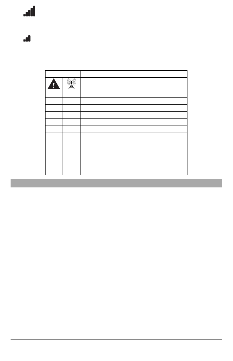
The 3G4010CF interface has four status LEDs. The following describes the status LEDs when the communicator is in normal
operating mode with the front cover in place.
Red
This LED indicates trouble conditions.
On (solid): Trouble requiring service
1 Flash: Wireless Network Trouble
2 Flashes: Battery Trouble
3 Flashes: Input Power Trouble
Blue
This LED indicates cellular radio activity. When this LED is on (solid), a phone line trouble condition
exists. This LED turns on when the interface switches to the wireless network (due to a landline trouble
condition). This LED will also flash once when the 3G4010CF transmits a signal and twice when the
3G4010CF receives a kiss-off from the central station.
NOTE: If the 3G4010CF is programmed to be the primary communicator, the blue LED will remain off,
but will still flash during the signal transmission as described above.
Yellow/Green
(Top)
This LED indicates signal strength and network technology. If the 3G4010CF is operating in over a 2G
channel, the LED will be YELLOW. If the 3G4010CF is operating over a 3G channel, the LED will be
GREEN. When this LED is On, the reception is optimal. This LED switches On only when the bottom
9

LED is on.
Yellow/Green
(Bottom)
This LED indicates signal strength and network technology. If the 3G4010CF is operating in over a 2G
channel, the LED will be YELLOW. If the 3G4010CF is operating over a 3G channel, the LED will be
GREEN. If this LED is Off and the Red LED is On, the Wireless Network service is unavailable (NO
SERVICE). This LED flashes when the Wireless Network reception is poor. If this LED is on, the
3G4010CF is able to communicate with the 3G (HSPA) or 2G (GPRS) network.
Service Mode
To view detailed trouble information on the status LEDs, the 3G4010CF must be placed in Service Mode by removing the front
cover. When in Service Mode, the status LEDs will indicate the trouble condition as follows.
Number of Flashes
RED BLUE
Trouble Type
1 OFF Wirelessnetwork trouble - unable to connect to cellular network
2 OFF Battery trouble - battery with low voltage output
3 OFF Input power trouble
1 Flashing Insufficient signal strength - poor location
2 Flashing C24 suppressed trouble
3 Flashing C24 communication configuration trouble
1 ON Radio/SIM trouble - radio or SIM unresponsive
2 ON Receiver not available trouble
3 ON Supervision trouble
4 ON Case or wall tamper is open
OFF - No trouble
Operating Principles
Simulated Landline Mode
The simulated landline provides the alarm control panel (with dialer interface) with a back up line in the event of PSTN line
trouble.
NOTE: The 3G4010CF must be programmed as a back-up communicator for Simulated Landline Mode to operate.
If the voltage on the landline terminals (TIP/RNG) drops below 2.8V for a period of between 10 seconds and 45 seconds -
depending on the alarm control panel connected to the T1/R1 terminals- the 3G4010CF switches the connected telephone
device to the cellular network.After waiting between 30 and 40 seconds,it checks the landline for one of the following:
lIf the landline has been restored, the 3G4010CF switches the connected device back to the landline, OR
lIf the landline is still down, the 3G4010CF continues the simulation until the landline is restored. The 3G4010CF will not
switch during ongoing calls.
NOTE: When the landline is down, the 3G4010CF provides a dial tone to any device connected to T1 and R1, including any
telephones on the premises. The phones on the premises will not, however, be able to dial out over the 3G4010CF.
Panel Transmission Monitoring (PTM)
The 3G4010CF can also monitor the panel’s attempt to communicate with the central station. If it determines that the panel is
having difficulty, it switches the line to the cellular network. This feature is only active when the 3G4010CF is configured as a
back up communicator. This feature is in addition to the regular line voltage detection.
The 3G4010CF monitors the phone line for four consecutive failed attempts within a 12-minute window. A failed attempt is
assumed to have occurred when a line seizure takes place during dialing (either the alarm panel or the customer telephone),
but no 1400Hz tone (Contact ID kiss-off) or 2025 Hz tone(SIA kiss-off)is sent from the receiver.
Once the conditions for a failed attempt are met, the 3G4010CF connects the panel to the cellular network to communicate the
events. When the 3G4010CF switches the line it stays in this mode until the panel hangs up. On the next event the 3G4010CF
restarts the error detection sequence before switching.
The 3G4010CF performs this sequence on any phone number that is detected on the line. Specific central station phone num-
bers can be programmed into the 3G4010CF if desired. Up to four, 20-digit numbers can be added to your profile at Connect
24. If programmed, the 3G4010CF will only look for a Contact ID or SIA kiss-off after these numbers are dialed. A Telephone
Line Monitoring trouble (PGM output activation and/or reporting code if applicable) is also activated and/or transmitted when
the PTM is activated. A restoral is sent at the end of the call.
10

Cellular Communications Sequence
When an alarm is triggered:
lThe control panel goes off-hook.
lThe 3G4010CF asserts a dial tone.
lThe Control panel dials the number of the central station. Ensure that the alarm panel inserts a minimum one second
pause, or has Dial Tone Search enabled before dialing the number.
lThe 3G4010CF detects the DTMF dialing and stops dial tone.
NOTE: The 3G4010CF is unable to decode pulse dialing.
If the panel is programmed for Contact ID format:
lThe 3G4010CF sends the required Contact ID dual-tone handshake to the panel.
lAfter receiving the handshake, the control panel transmits an alarm message in Contact ID format.
lThe 3G4010CF decodes and transforms the ContactID digits into an IP packet and sends it to the central station receiver
over the cellular network.
lThe central station receiver acknowledges the alarm and sends a command to the 3G4010CF to generate the cor-
responding 1400Hz Kiss-off signal for a minimum of 800 msec.
After the 3G4010CF generates a Kiss- offsignal, it sends the next alarm or, if no further alarms need to be sent, the control
panel goes on-hook.
If the panel is programmed for SIA (300 baud) format:
lThe 3G4010CF sends the required SIA handshake to the panel.
lAfter receiving the handshake, the control panel transmits an alarm message in the SIA format.
lThe 3G4010CF decodes and transforms the SIA events into an IP packet that it sends to the central station receiver over
the cellular network.
lThe central station’s receiver acknowledges the alarm and sends a command to the 3G4010CF to generate the cor-
responding 2025Hz kiss-off signal for a minimum of one second.
lAfter the 3G4010CF generates a kiss-offsignal, it sends the nextalarm or, ifno further alarms need to be sent,the control
panel goes on hook.
NOTE: The 3G4010CF automatically adjusts the order of the handshakes based on the last format the control panel used to
transmit an event.
Inputs
The 3G4010CF has four inputs that can be used to trigger specific communications. These events will transmit using the
Contact ID or SIA format with Inputs 1-4 reporting as [991] to [994] respectively.
Default settings are:
INPUT 1- AC LOSS INPUT 3 - FIREALARM
INPUT 2 - FIRE SUPERVISORY INPUT 4 - SYSTEM TROUBLE
Inputs can be configured as follows:
Normally Open - input will activate when a short condition is detected between the terminal and COM.
Normally Closed - input will activate when an open condition is detected between the terminal and COM.
Single End of Line - input will activate when a short or open condition is detected between the terminal and COM and will
restore when a 5.6Kohm resistor is detected between the terminal and COM.
NOTE: These inputs are programmable to communicate using either the Contact ID or SIA format.
NOTE: For UL/ULC listed installations, End of Line supervision must be used for all inputs.
NOTE: When the 3G4010CF is configured in land line mode, these inputs should be restricted to monitoring of trouble con-
ditions.
Outputs
The 3G4010CF has four programmable outputs to activate in response to the associated events. Refer to the 3G4010CF Wir-
ing Diagram (Figure 2) at the back of this manual.
Activating the Outputs
The 3G4010CF has four open collector outputs capable of a maximum of 50mA. Internal events on the 3G4010CF can trigger
the outputs to turn on an LED or activate an input on the host panel. The default settings are as follows.
OUTPUT 1 Landline Trouble - Output is normally high and will switch to ground when the telephone line is down.
OUTPUT 2 Cellular Module or Network Trouble - Output is normally high and will switch to ground when the 3G4010CF can
not communicate with the 3G or 2G network.
OUTPUT 3 Power Supply or Battery Trouble - Output is normally high and will switch to ground when there is a problem with
the power source.
OUTPUT 4 General Module Trouble - Output is normally low and will switch to high when a Cellular Network Trouble, Power
Supply/Battery Trouble, and/or a Failure to Communicate (FTC) trouble is detected.
NOTE: PGM4 must be connected to the control panel as shown in Figure 4 (Residential applications) or Figures 8-9 (Com-
mercial applications). Program the control panel input Zone/Point as 24hr ‘Supervisory’ with keypad-only notification when
activated. Output 4 on the 3G4010CF mustbe set as ‘Active High’.
11

NOTE: Once an output has been activated automatically, it will not restore its state until all the causes of activation are cleared.
Reporting Codes
3G4010CF Reporting Codes CID SIA Programmable Comments
Zone 1 Activation E301 991 AT 991 YES AC Loss*
Zone 1 Restoral R301 991 AR 991 YES AC Loss Restore *
Zone 2 Activation E200 992 FS 992 YES Fire Supervisory*
Zone 2 Restoral R200 992 FV 992 YES Fire Supervisory Restore*
Zone 3 Activation E110 993 FA 993 YES Fire *
Zone 3 Restoral R110 993 FH 993 YES Fire Restore *
Zone 4 Activation E300 994 YX 994 YES System Trouble *
Zone 4 Restoral R300 994 YZ 994 YES System Trouble Restore *
PSTN Line Down E351 000 LT 000 FIXED Telco 1 Fault
PSTN Line Restoral R351 000 LR 000 FIXED Telco 1 Fault Restore
Periodic Test E603 XXX RP XXX FIXED Test Transmission <Receiver Path>
Periodic Test with Trouble E608 XXX RY XXX FIXED Test Transmission <Receiver Path>
Radio Activation R552 000 RS 000 FIXED Remote Programming Successful
Internal Buffer Full E624 000 JL 000 FIXED
FTC Restoral R354 000 YK 000 FIXED Communications Restored
Firmware Update Successful R901 000 LS 000 FIXED
Firmware Update Fail E902 000 LU 000 FIXED
Firmware Update Begin E901 000 LB 000 FIXED
System Tamper E145 000 ES 000 FIXED Expansion Module Tamper
System Tamper Restore R145 000 EJ 000 FIXED Expansion Module Tamper Restore
* C24 Communications default value
NOTE: The 3G4010CF does not support remote programming (local hardware default required). Upon activation through Con-
nect 24, the product will operate as described in this manual.
Swinger Shutdown
To prevent "runaway" signals to the central station, the 3G4010CF is equipped with Swinger Shutdown which limits certain
trouble events to a maximum of four reports every 24 hours. The condition will restore and the counter will reset at midnight.
Swinger Shutdown applies to the following trouble conditions:
lSystem Tamper/Restore
lLow Battery Trouble/Restore
lTLM Trouble/Restore
lInput Power Trouble/Restore
lFTC Restore
Hardware Default
A local hardware default is required in order to update the unit with the latest configuration from C24 Communications.
To perform the hardware default, follow these steps:
1. Power down the unit (remove primary DC power and remove the backup battery) and remove all connections to Zone1,
Zone 2, PGM1 and PGM.
2. Connect a wire between Z2 (terminal 7) and PGM2 (terminal 8) or Z1 (terminal 13)and PGM1 (terminal 7).
3. Power up the radio by connecting the battery first and then primary DC power.
4. Wait for 20 seconds and then completely power down the unit.
5. Disconnect the wire between the Zone and PGM terminals.
6. Power up and let the unit complete the update (the LEDs will stop flashing when the downloading is complete).
NOTE: Failure to perform hardware default will result in the unit transmitting with the previously programmed configuration.
Communicator Reset/Update
The firmware of the device can be updated over Cellular or PC-Link:
lWhen the firmware update begins, all LED are ON.
12

RED BLUE
Yellow/Green
(Top)
Yellow/Green
(Bottom)
ON ON ON ON
lDuring the firmware update processthe LEDs will be cycled individually in a chaser pattern. (different from the Advanced
Carrier Selection pattern)
RED BLUE Yellow/Green
(Top)
Yellow/Green
(Bottom)
FLASH ON OFF OFF OFF
OFF FLASH ON OFF OFF
OFF OFF FLASH ON OFF
OFF OFF OFF FLASH ON
FLASH ON OFF OFF OFF
OFF FLASH ON OFF OFF
OFF OFF FLASH ON OFF
OFF OFF OFF FLASH ON
lAfter a successful update, the unit will automatically restart.
NOTE: Several resets will take place during a single Firmware update session.
NOTE: The unit will re-request programming after firmware update; the version number will be updated and viewable via C24
Communications.
NOTE: Unit must not be powered down while Firmware Update Takes Place.
NOTE: Unit will not process remote firmware update requests while it exhibits the following trouble, if the trouble occurs after
the unit has processed the firmware update request, it will not interrupt the firmware update request.
• Input Power Trouble
• Low Battery Trouble
Low Power Radio Shutdown
When the battery voltage reaches the low battery threshold of 9.6V, the unit turns off the radio to prevent unnecessary network
registrations. In this state, the unit does not communicate any events.
Radio shutdown is indicated by the LEDs as follows:
lRed LED indicates low battery trouble.
lTwo green LEDs blinking on/off together indicates the radio is not ready.
This LED sequence will display until the low battery voltage is restored and the radio is enabled again.
SMS Command and Control
NOTE: For UL/ULC installations, this feature has not been investigated by UL/ULC and its use is not permitted.
The user can remotely arm/disarm their security panel and control PGM outputs by following these steps:
Arming/Disarming the Security Panel
1. Set up a PGM output to Remote Arming in C24 Communications
2. Ensure this PGM output is connected to a relay to their security panel zone
3. Set up the zone on the security panel as momentary or maintained arming
a. If the Security Panel uses Momentary key switching, the configuration on Communicator PGM shall be with a time
field of 05 (in this configuration, both arm and disarm will generate the pulse)
b. If the security Panel uses maintained key arming, the configuration on the communicator PGM shall be filled with a
time field of 00
4. Optionally the panel arm state can be configured for the communicator to detectby setting a panel PGM output to reflect
panel arm state, have that relay connected to a communicator zone configured to follow panel arm state.
Remote Control of PGM
1. Set up a PGM or both PGM output to Remote Control PGM configuration
a. PGM can be latched or timed
i. setting the PGM timer to 00 will configure the PGM to be latched, it will not turn off unless the turn off command is
received
ii. setting the PGM timer with a time value between 1 second to 255 seconds will configure the PGM to be timed,
the PGM will activate
13

2. Configure in C24 Communications the Phone Number allowed to use SMS command and control and the accesscode
a. Up to 6 different phone numbers can be programmed to perform SMS command and control
b. The password can be 4 to 8 alphanumeric characters and it will not be case sensitive
The SMS command and control can be sent in the following format:
For arming/disarming the Security Panel
Arm <access code>, example Arm 12345678
For activating/deactivating a specific PGM
Activate <PGM #> <accesscode>, Activate 1 12345678
The following SMS command and control operations are available.
lArming
Language Command Label (shall not be case sensitive)
English Arm
French Armement
Spanish Armado
lDisarming
Language Command Label (shall not be case sensitive)
English Disarm
French Desarmement
Spanish Desarmado
lActivate PGM
Language Command Label (shall not be case sensitive)
English Activate
French Activation
Spanish Activar
lDeactivate PGM
Language Command Label (shall not be case sensitive)
English Deactivate
French Desactivation
Spanish Desactivar
lStatus Request
Language Command Label (shall not be case sensitive)
English Status Request
French Etat Démandé
Spanish Petición de Estado
Invalid command will be sent when no zones are programmed to read securityarm status.
lHelp
Language Command Label (shall not be case sensitive)
English Help
French Aide
Spanish Ayuda
Help command will return all the commands available corresponding to the language of the help command
being sent.
Phone Number Call Direction
The user has the abilityto program the PTM phone numbers to receiver group 1 or receiver 2.
14

The programmed number in Communicator must also be programmed as the panel phone number. When the communicator
detects the phone number it will communicate to the receivers to the corresponding group.
NOTE: If no PTM phone number is programmed, all panel calls will go to Receiver Group 1.
Troubleshooting Guide
Powering up the 3G4010CF – when powering up the 3G4010CF, always connect the battery first (if used) before connecting
primary DC power from the control panel or transformer.
Wiring Primary – R-1/T-1 of 3G4010CF to RING/TIP of control panel, DC power from control panel or DC transformer to DC
input, backup battery.
Wiring Backup – Incoming line to RING/TIP on 3G4010, R-1/T-1 of 3G4010CF to RING/TIP of control panel, R-1/T-1 of control
panel to house phones, DC power from control panel or DC transformer to DC input, backup battery.
Testing Communications – when the 3G4010CF transmits a signal for the control panel, or for an internal transmission, the
BLUE light will flash one time when the signal is transmitted and two times when it gets a kiss-off.
SIM – the SIM should be activated at least 24 hours prior to installation. The 3G4010CF will show signal strength with an inact-
ive SIM, however it will display the signal strength of any available wireless network. The SIM mustbe active to ensure the sig-
nal strength displayed is that of the wireless network provider for which the SIM belongs to.
Panel Programming – the control panel should be programmed to communicate Contact ID or SIA exactly the same way it
would be programmed to communicate Contact ID or SIA over the telephone line.
Green/Yellow
LED Status
What it
means: CSQ Values Signal Strength Status
Both Signal Strength
LEDs ON
Excellent
Signal
Strength
14+ lUnit can be installed in the current mounting location.
Top LED FLASHING with
bottom LED ON
Excellent
Signal
Strength
11-13 lUnit can be installed in the current mounting location.
Bottom LED ON Good Signal
Strength 7-10 lUnit can be installed in the current mounting location.
Bottom LED FLASHING Poor Signal
Strength
5-6
(no trouble)
1-4
(with trouble)
lEnsure the antenna cable is plugged securely into the radio
connector.
lIf the SIM is active, connect a battery to the unit and test
various locations for good/excellent signal strength.
lConnect an antenna extension kit (GS-15ANT, GS-25ANT,
GS-50ANT or GS8-ANTP).
Both LEDs OFF No Signal
Strength 0
lIf the red LED is also FLASHING, refer to the RED LED chart.
lVerify SIM card is activated.
lEnsure the antenna cable is plugged securely into the radio
connector.
lIf the SIM is active, connect a battery to the unit and test
various locations for good/excellent signal strength.
lConnect an antenna extension kit (GS-15ANT, GS-25ANT,
GS-50ANT or GS8-ANTP).
Both LEDs Flashing
ON/OFF together
Signal
Strength is
invalid
N/A Radio is in process of network registration.
Both LEDs Alternating Radio Reset
Sequence N/A Radio is performing a Reset. If the issue persists, please verify the
SIM card is inserted correctly.
NOTE: When the Signal Strength LED is showing Green, it indicates your communicator is connected to a 3G Tower. When
the Signal Strength LED is showing Yellow,it indicates your communicator is connected to a 2G Tower.
Blue LED Status
(Normal Mode) What It Means: Wireless Communicator Status/Communication Indicator
Blue LED ON When used as a backup communicator, the blue LED will be ON when there is a no phone line
connected to the 3G4010CF TIP and RING, or the line voltage goes below 2.8VDC.
Blue LED OFF A good phone line is connected to the 3G4010CF . (more than 2.8 VDC detected across the 3G4010CF
TIP and RING terminals).
15

Blue LED Status
(Normal Mode) What It Means: Wireless Communicator Status/Communication Indicator
Blue LED
FLASHING
The blue LED will flash one time when the 3G4010CF transmits a signal and two times when a kiss-offis
received.
NOTE: Blue LED is always OFF when 3G4010CF is used as a primary communicator.
# of
Flashes Trouble Type Trouble Notes
Red Blue
On On No Signal Strength
lVerify SIM card is activated.
lEnsure the antenna cable is plugged securely into the radio connector.
lIf the SIM is active, connect a battery to the unit and test various locations for
good/excellent signal strength.
lConnect an antenna extension kit (GS8-ANTP, GS-15ANT, GS-25ANT or GS-
50ANT).
1 Off Wireless Network Trouble
lEnsure the SIM card has been activated.
lThe antenna cable should be plugged securely into the radio connector.
lEnsure there is good signal strength (at least one green light ON).
lVerify the installation area is not experiencing a network outage.
2 Off Battery Trouble
lIf a battery is not used in the installation, ensure that the "Internal Battery
Connected" is not selected in C24 Communications.
lIf a battery is used in the installation, verify the battery is connected properly
lMeasure the battery under load and verify it is charged to at least 11.8VDC. If
not, wait at least 1 hour for the battery to charge.
lRemove the battery and measure the voltage; the voltage should be at least
11.8VDC.
lVerify the input DC supply is rated at 13.8VDC @ 180mA minimum.
lReplace battery
3 Off Input Power Trouble lEnsure the power source connected to the 3G4010 is providing 13.8VDC @
180mA.
1 Flash Insufficient Signal Strength
lEnsure the antenna cable is plugged securely into the radio connector.
lIf the SIM is active, connect a battery to the unit and test various locations for
good/excellent signal strength.
lConnect an antenna extension kit (GS8-ANTP, GS-15ANT, GS-25ANT or GS-
50ANT)
2 Flash Not Used
3 Flash C24 Communications
Configurations Trouble
lEnsure the SIM card is activated and correctly initialized through C24
Communications.
1 On Radio/SIM Trouble lEnsure the SIM Card is inserted correctly and firmly.
lEnsure the antenna cable is plugged securely into the radio connector.
2 On Receiver Not Available
Trouble
lContact the monitoring station to verify that the 3G4010CF programming is
correct (port, IP address, DNIS).
lContact your central station to verify they are not experiencing any receiver
issues.
3 On Supervision Trouble lContact your central station to verify they are not experiencing any receiver
issues.
4 On Tamper Trouble lEnsure the front cover is secured and the case tamper is closed.
The Red light will flash to indicate various trouble conditions outlined previously. If multiple trouble conditions are present, the
red light will flash according to the highest priority trouble. For example, if both a 3G4010CF wireless network trouble (one
flash) and a low battery trouble (two flashes) are present; the red light will flash one time. Once the 3G4010CFwireless network
trouble condition is corrected, the red light will then begin flashing two times.
General Troubles With Your System
The control panel is displaying a
telephone line trouble condition
lEnsure T1 and R1 of the 3G4010CF are wired to the TIP and RING terminals
of the control panel.
lIf the 3G4010CF is being used as the primary communicator, the blue light will
always be OFF.
lIf the 3G4010CF red light is FLASHING, refer to the troubleshooting chart in
this guide.
16

General Troubles With Your System
The control panel displays a
communication trouble condition
lEnsure the panel is programmed for Contact ID or SIA.
lEnsure the control panel does not indicate a TLM trouble condition.
lIf the 3G4010CF red light is FLASHING refer to the troubleshooting chart in
this guide.
No signals are received at the central
station but no trouble condition is
displayed
lEnsure the control panel hasa central station phone number programmed.
lEnsure the control panel has the correct account number programmed.
lVerifythe reporting codes are programmed or the auto Contact ID/SIA option
is enabled.
lEnsure the control panel communicator is enabled.
lConnect a handset to T1 and R1 of the 3G4010CF in monitor mode to verify
the control panel is trying to communicate.
Not receiving internal signals generated
directly from the 3G4010
lEnsure the 3G4010CF was initialized with the correct account number. This
can be checked by logging into the C24 Communications website.
lEnsure that there are no trouble conditions on the 3G4010CF.
The phone line is seized when the
3G4010 is connected
lVerify correct phone line wiring.
lEnsure the Ringer Equivalency Number (REN) is not being exceeded on the
line.
General Information
Removing/Connecting the antenna
lTo remove the antenna from the 3G4010CF, place your thumb on the end of
the connector at the modem, then place a screwdriver between the modem
and connector. Gently turn the screwdriver away to ‘pop’ out the connector
from the modem.
lTo install the antenna, firmly push the connector into the modem until it ‘snaps’
into place.
Enrolling a 3G4010CF
lThe 3G4010CF can be enrolled by going through the GVRU voice prompt,
and completing the activation of the SIM card, and the initialization of the
3G4010CF.
lThe 3G4010CF can also be enrolled using the C24 Communications website
(www.connect24.com) or the C24 Communications mobile site
(m.connect24.com).
SIM card activation period lA SIM card can take up to 24 hours to be activated by the provider. However, it
typically takes less than an hour for the SIM card to be activated.
Checking SIM status
lGo to www.connect24.com and login. A search can be performed for a specific
account and its current status
lSIM status can also be checked through the GVRU.
Critical Shutdown on 3G4010CF backup
battery (with no DC input applied)
lIf the 3G4010CF backup battery is used and is below 10.5VDC, the unit will go
into critical shutdown.
lThe critical shutdown state will be displayed by the red light flashing followed
by the yellow and two green lights flashing.
lThe lights will continue to flash in this sequence until the battery is charged
above 11.8VDC.
Swinger Shutdown for 3G4010CF
Troubles
lTrouble events can send a maximum of 4 troubles and restorals per day.
lSwinger Shutdown only affects signal transmissions, not the functionality of the
3G4010CF lights or PGM outputs.
lSwinger shutdown is reset at midnight or upon a full power cycle of the
3G4010CF.
It is recommended that the productis tested at least once per year.
17

3G4010CF Wiring Diagrams
Figure 2: 3G4010CF Wiring Diagram
5
41 23 6 7 8 9 10 11 14 15 16 17
LE
LI O1 O2 O3 O4
+OC
13
12
AS
L1 L2 L3 L4
1K5
T
I
P
R
I
N
G
3G4010CF
32
DC INAUX
2 31
COM
41
COMT1 R1TIP RING
4
PGM ZONE
+
-
RJ-45
Earth-ground
Ground wire from
building electrical
installation
}
GROUND
CONNECTION
Tighten nut to break paint &
make good connection to
the cabinet.
Nut
Nut
Bolt
Lock washer
Lock washer
Star washer
Cabinet
Alarm Control Panel with
Dialler Interface
(Supports Contact ID and
SIA formats)
Connect to Power Supply
Terminals +12/COM
Telephone Line
Connection
Supervision
Relay
RM2-UL Installations
Connect relay contacts to
a zone input on the alarm
control panel for 3G4010CF
troubles supervision
(24hr-type zone)
Optional
use of PGM
output (See
Programming)
WARNING!
HIGH VOLTAGE. DISCONNECT AC
POWER & TELEPHONE LINES
PRIOR TO SERVICING
WARNING: Incorrect connections may result in PTC failure or improper operation. Inspect wiring and ensure connections are correct before turning on.
All circuits are classified for UL installations as Power Limited/Class II Power Limited except for the battery leads which are not Power Limited. Do not route any wiring over circuit boards. Maintain at least 1”
(25.4mm) separation. A minimum 1/4” (6.4mm) separation must be maintained at all points between Power Limited wiring and all other Non-Power Limited wiring. Route wires as indicated in the diagram.
Phone line connection is required only for back-up configurations. In stand-alone applications, no other communication technology is required for Fire Alarm Monitoring. Refer to Fig. 4 for wiring details.
Suggested compatible DACT models for use with 3G4010CF are DSC models: PC4020CF with PC470I Interface or PC5020CF with PC5700 Interface
(Use No. 26 AWG wires for the connection to PSTN)
Phone line connection is required only for back-up
configurations. In stand-alone applications, no other
communication technology is required for Fire Alarm
Monitoring. Refer to Fig. 4 for wiring details.
Suggested compatible DACT models for use with
3G4010CF are DSC models: PC4020CF with
PC470I Interface or PC5020CF with PC5700 Interface. For ULC Fire Monitoring installations fire alarm signals shall be sent simultane-
ously over POTS line (using the dialler) and over the wireless network (using
3G4010CF). Connect alarm output from control panel (PGM) to the input on the
3G4010CF that is programmed as a Fire Alarm Input.
Examples of Control Units/Subscribers Units or Power Supplies
compatible models: DSC PC1864, PC1832, PC1616, PC5204, etc.
This connection
is necessary
Inputs to be connected to dry contact outputs from alarm control panel with 5.6K
Ω EOL resistors. These inputs are typically used to interface with fire alarm
panels that do not have a dialer interface and use the fire alarm, fire supervisory
or fire trouble output relay contacts to send the events to the communicator.
NOTE: For Zone Inputs/PGM outputs, DC IN, AUX wiring, use size No. 18-22
AWG conductors. Do not use shielded wires.
The 3G4010CF shall be installed in accordance with the following, as applicable: NFPA 70, "National Electrical Code.", NFPA 72, "National Fire Alarm Code.", National Building Code (NBC); CSA C22.1 -
Canadian Electrical Code, Part 1; Section 32, CAN/ULC S561 - Standard for the Installation and Services for Fire Signal Receiving Centre and Systems; CAN/ULC-S302 - Standard for Installation and
Classification of Burglar Alarm Systems for Financial and Commercial Premises, Safes and Vaults; CAN/ULC S301 - Standard for the Signal Receiving Centre Burglar Alarm Systems and Operations, Local
Authorities Having Jurisdiction (AHJ) and Manufacturer's Installation Instructions.
18

Figure 3: 3G4010CF Module Wiring Diagram - Standalone Configuration
These inputs are typically used to
interface with fire alarm panels that do
not have a dialer interface and use the
fire alarm, fire supervisory or fire
trouble output relay contacts to send
the events to the communicator.
3G4010CF
Connect relay contacts to a zone
input on the alarm control panel
for 3G4010CF troubles supervision
(24 h type zone)
NOTE: If the control panel PGM output connected to the 3G4010CF input latches (remains closed) after an alarm has
occurred, the 3G4010CF input will remain active. The latched PGM output must be reset or future alarms will not be reported
via the zone input of the 3G4010CF and additional alarms may be triggered when the 3G4010CF is locally or remotely restar-
ted. Please contact panel vendor for details on how to reset the control panel PGM.
Figure 4: Power Supply Wiring Diagram
PS4085
+12V
COM ACT LBT TEST +BAT
AC IN
TEST - CHARGER TROUBLE OUTPUT 50mA, 12V Max.
LBT - LOW BATTERY OUTPUT 50mA, 12V Max.
ACT - AC FAILURE OUTPUT 50mA,12V Max.
Primary
120VAC
60Hz, 0.3A
TRANSFORMER
ATC Frost Model FTC3716
SPECIAL APPLICATION OUTPUT
RATING: 11.5VDC - 12.6VDC,
700mA max. Use for DSC,
Model 3G4010CF
WARNING!
HIGH VOLTAGE. DISCONNECT AC
POWER & TELEPHONE LINES
PRIOR TO SERVICING
These outputs shall be connected to zone inputs of an alarm control panel in order to provide the required trouble supervision
(visual and audible indication required at the control panel). The outputs are active low (switched to ground) and can be con-
nected to a control panel directly or by using a listed supervision relay (suggested model: DSC, RM-2 or RM1C).
19

Figure 5: Telephone Connection
RED (R)
GREEN (T)
GRAY (R)
BROWN (T)
RJ-31X
RING
TIP
CONTROL PANEL
Incoming
Phone line
Handset
RI
TI
T1
R1
TIP
RING
4
321 5
3G4010CF
TIP T1 R1
RING
Figure 6: Power Supply and Supervision Wiring Diagram
+12VDC
GND
Control
Panel
EOL
Resistor
See Note 3
DSC
RM-2
RELAY
NC
C
NO
ZONE
TERMINALS
(See Note 1)
- +
+12VDC
GND
CONTROL PANEL
Aux Power
+ -
DSC
Supervision
Relay
See Note 2
17
16
151412 18
13
11
1097 86
19
Z4
Z3Z2
COM 20
Z1
AUX
+
PGM
3
PGM
1
PGM
4
COM
3G4010CF
PGM
3
DC IN
+ -
DSC
Supervision
Relay
See Note
Power Supply
Provides power to the
3G4010CF Module
NOTES:
1. Program the zone/point as “Supervisory” type
with keypad only annunciation when in alarm.
Do NOT use a zone/point that is normally used
for 2-wire smoke detectors.
2. The power supervision relay (RM-2 or RM1C)
is only used when the 3G4010CF is not
powered by the control panel. When the radio
is powered by the control panel, the relay is not
required since a loss of input power will
generate a signal to the CMC.
3. Output 4 on the 3G4010CF must be set as
“Active High” (default).
20
Table of contents
Other DSC Cell Phone manuals

DSC
DSC IT-410 Assembly instructions

DSC
DSC TL280 User manual

DSC
DSC GS3125 Series User manual

DSC
DSC Skyroute CL3050 Operating instructions

DSC
DSC GS3125 Series User manual

DSC
DSC TL280R Operating and maintenance instructions

DSC
DSC TL2803GR User manual

DSC
DSC LE4000 User manual

DSC
DSC 3G3070 User manual

DSC
DSC GS2060 User manual

DSC
DSC Skyroute CL3050 ver 1.2 Operating instructions

DSC
DSC 3G2080 User manual

DSC
DSC LE4020 User manual

DSC
DSC 3G2075 User manual

DSC
DSC GS3055-IG User manual

DSC
DSC neo Power Series User manual

DSC
DSC 3G4010 User manual

DSC
DSC T-Link TL300 User manual

DSC
DSC neo TL280E User manual

DSC
DSC TL260GS User manual