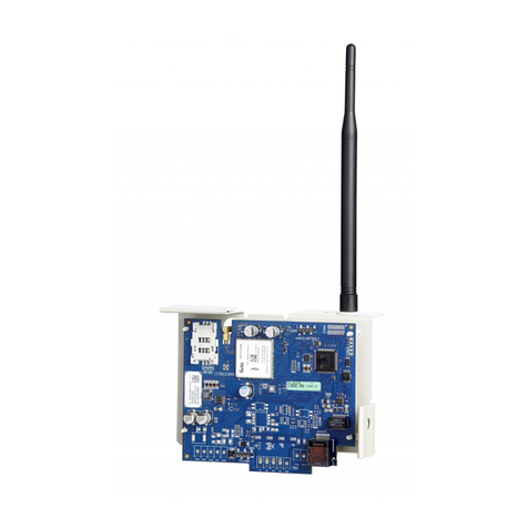
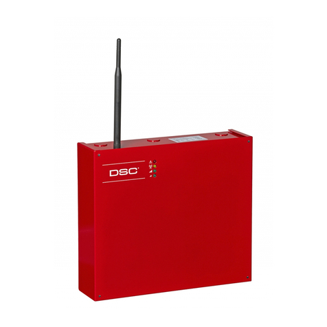
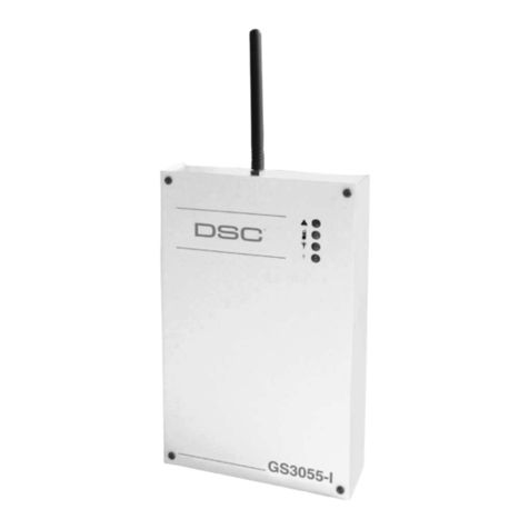
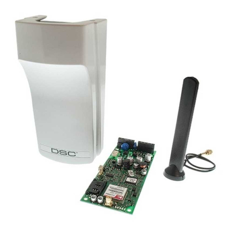
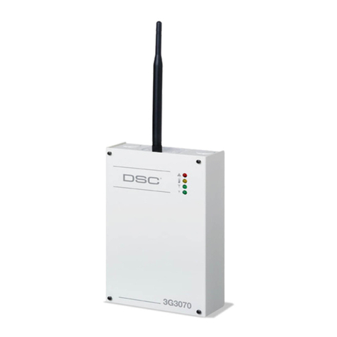
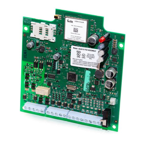
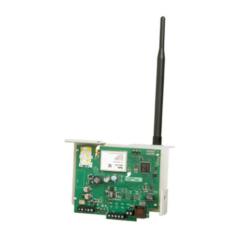
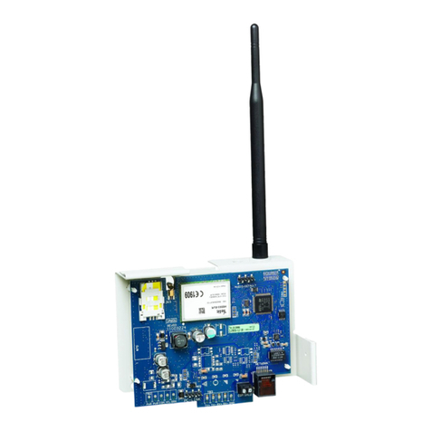
DSC LE4000 User manual

LE4000
LTE Wireless Alarm Communicator
Installation Guide
V5.0
Warning: This manual contains information on limitations regarding product use andfunction and information on the lim-
itations as to liability of the manufacturer. The entire manual should be carefully read.

Safety Information
IMPORTANT
The equipment is fixed, wall-mounted and shall be installed in
the position specified in these instructions. The equipment
enclosure must be fully assembled and closed, with all the
necessary screws/tabs and secured to a wall before operation.
Internal wiring must be routed in a manner that prevents:
- Excessive strain on wire and on terminal connections
- Loosening of terminal; connections
- Damage of conductor insulation
WARNING: Never install this equipment during a lightning
storm!
Instruct the end-user to:
- Not attempt to service this product. Opening or removing cov-
ers may expose the user to dangerous voltages or other risks.
Any servicing shall be referred to trained service persons only.
- Use authorized accessories only with this equipment.
Do not dispose of the battery in fire or water. Disposing of the
battery in a fire will cause rupture and explosion.
Do not dispose of the waste battery as unsorted municipal
waste. Consult your local regulations and /or laws regarding
recycling with regard to this lead-acid battery. Doing so will
help protect the environment. Some of the materials that are
found within the battery could become toxic if not disposed of
properly and may affect the environment.
This equipment, LE4000, is fixed and shall be installed by Ser-
vice Persons only (Service Person is defined as a person hav-
ing the appropriate technical training and experience
necessary to be aware of hazards to which that person may be
exposed in performing a task, and of measures available to
minimize the risks to that person or other persons). It shall be
installed and used within an environment that provides the pol-
lution degree max 2, over voltages category II, in non-haz-
ardous, indoor locations only. This manual shall be used with
the Installation Manual of the relevant alarm control panel. All
instructions specified within that manual must be observed.
EULA
IMPORTANT - READ CA REFULLY: DSC Sof tware purchased with or without Product s and Com-
ponents is copyrighted andis purchased under the following license terms:
This End-User License Agreem ent (“E ULA”) is a legalagreement between You (t he company, indi-
vidual or entity who acquired the Soft ware and any related Hardware) and Digital Security Controls,
a division of Tyco Safet y Product s Canada Ltd. (“DSC”), the m anufact urer of the integrated secur-
ity systems and the developer of the software and any related products or components
(“HARDWARE”) which You acquired.
If the DSC sof tware product (“S OFTWARE PRODUCT” or “S OFTWARE”) is intended to be accom -
panied by HARDWARE, and is NOTaccompaniedby new HARDWARE, You may not use, copy or
installthe SOFTWARE PRODUCT. The SOFTWARE PRODUCTincludes computer software, and
may include associated media, printed m aterials, and “online” or elect ronic document ation.
Any sof tware provided along with t he SOFTWARE PRODUCT that is associated with a separate
end-user license agreement is licensed to You under t he term s of that license agreement.
By installing, copying, downloading, storing, accessing or otherwise using the SOFTWARE
PRODUCT, You agree unconditionally to be bound by t he terms of t his EULA, even if this EULA is
deemed t o be a m odificat ion of any previous arrangement or contract . I f You do not agree t o t he
term s of this EULA, DSC is unwilling to license t he SOFTWARE PRODUCT to You, and You have
no right t o use it.
SOFTWARE PRODUCT LICENSE
The SOFTWARE P RODUCT is prot ect ed by copyright laws and internationalcopyright t reaties, as
wellas other intellectual property laws and treaties. The SOFTWARE PRODUCTis licensed, not
sold.
1. GRANT OF LICENSE This EULA grants You the following ri ghts:
Software Installation and Use - For each license Y ou acquire, You m ay have only one copy of
the SOFTWARE PRODUCT installed.
Storage/Network Use - The SOFTWARE PRODUCT may not be inst alled, accessed, displayed,
run, shared or used concurrently on or from different computers, including a workstation, term inal
or other digital electronic device (“Device”). In other words, if You have several workstations, You
will have to acquire a license f or each workst ation where the SOFTWARE willbe used.
Backup Copy - Y ou may m ake back-up copies of the SOFTWARE PRODUCT, but You may only
have one copy per license installed at any given time. You may use the back-up copy solely for
archival purposes. Except as expressly provided in this EULA , You m ay not ot herwise m ake cop-
ies of the SOFTWARE PRODUCT, including the printed mat erials accompanying the SOFTWARE.
2. DESCRIPTION OF OTHER RIGHTS AND LIMI TATIONS
Limitati ons on Reverse Engineering, Decompilation and Di sassembly - You may not
reverse engineer, decompile, or disassem ble the SOFTWA RE PRODUCT, except and only to t he
ext ent t hat such act ivity is expressly perm itted by applicable law notwithstanding t his limitation.
You may not make any changes or m odif icat ions t o t he Soft ware, without t he writt en perm ission
of an officer of DSC. You may not remove any proprietary notices, marks or labels from the Soft-
ware Product. You shallinstitute reasonablemeasures to ensure compliance with the terms and
conditions of this EULA.
Separation of Components - The S OFTWARE PRODUCT is licensed as a single product . I ts com -
ponent parts may not be separated for use on more t han one HARDWARE unit.
Single INTEGRATED PRODUCT - I f Y ou acquired this SOFTWARE with HARDWARE, then t he
SOFTWARE PRODUCT is licensed with t he HARDWARE as a single int egrated product . I n t his
case, the SOFTWARE PRODUCT may only be used with the HARDWARE as set forth in this
EULA.
Rental - You m ay not rent, lease or lend the SOFTWARE PRODUCT. You may not make it avail-
able to ot hers or post it on a server or web site.
Software Product Transfer - You may transfer allof Your rights under this EULA only as part of a
permanent sale or t ransfer of t he HARDWARE, provided You retain no copies, You transf er all of
the SOFTWARE PRODUCT (including all component part s, the media and printed mat erials, any
upgrades and this EULA), and provided the recipient agrees to the terms of this EULA. If the
SOFTWARE PRODUCT is an upgrade, any transfer must also include all prior versions of the
SOFTWARE PRODUCT.
Termination - Without prejudice to any other rights, DSC may terminate this EULA if You fail to
com ply with t he terms and conditions of t his EULA. In such event , You m ust destroy all copies of
the SOFTWARE PRODUCT and allof its com ponent parts.
Trademarks - This EULA does not grant You any rights in connection with any trademarks or ser-
vice m arks of DSC or its suppliers.
3. COPYRIGHT
Alltitle and intellectual property rights in and to the SOFTWARE PRODUCT(including but not lim-
ited to any images, photographs, and text incorporated into the SOFTWARE PRODUCT), the
accompanying printed materials, and any copies of the SOFTWARE PRODUCT, are owned by
DSC or its suppliers. You may not copy the printed materials accompanying the SOFTWARE
PRODUCT. All title and intellectual property rights inand to the content which may be accessed
through use of the SOFTWARE PRODUCT are the property of the respect ive content owner and
may be protected by applicable copyright or other intellectual property laws and treaties. This
EULA grants You no rights to use such content. All rights not expressly granted under this EULA
are reserved by DSC and its suppliers.
EXPORT RESTRICTIONS - You agree that You will not export or re-export the SOFTWARE
PRODUCT to any country, person, or ent it y subject t o Canadian export restrictions.
CHOICE OF LAW - This Software License A greement is governed by t he laws of the P rovince of
Ontario, Canada.
ARBITRATION - All disputes arising in connection with t his Agreement shallbe determ ined by final
and binding arbitrat ion in accordance with the Arbitration Act, and the part ies agree t o be bound by
the arbitrat or’s decision. The place of arbitration shallbe Toronto, Canada, and the language of the
arbitrat ion shallbe English.
LIMITED WARRANTY
NO WARRANTY - DSC PROVIDES THE SOFTWARE “AS IS” WITHOUT WARRANTY. DSC
DOES NOTWARRANT THA T THE SOFTWA RE WILL MEET Y OUR REQUIREM ENTS OR THAT
OPERATION OFTHE S OFTWARE WILL BE UNI NTE RRUPTED OR ERROR-FREE.
CHANGES IN OPERATING ENVIRONMENT - DSC shall not be responsible for problems
caused by changes in the operat ing characteristics of t he HARDWARE, or f or problems in the inter-
actionof the SOFTWARE PRODUCTwith non-DSC-SOFTWARE or HARDWARE PRODUCTS.
LIMITATION OF LIABILITY; WARRANTY REFLECTS ALLOCATION OF RISK - IN ANY
EVENT, IF ANY STATUTE IMPLIES WARRANTIES OR CONDITIONS NOTSTATED IN THIS
LICENSE AGREEMENT, DSC’S ENTIRE LIABILITY UNDER ANY PROVISION OF THIS
LICENSE AGREEMENTSHALL BE LIMITED TO THE GREATER OF THE AMOUNT ACTUALLY
PAID BY YOU TO LICENSE THE SOFTWARE PRODUCT AND FIVE CANADIAN DOLLARS
(CAD$5.00). BECAUSE SOME JURISDICTIONS DO NOT ALLOW THE EXCLUSION OR
LIMI TATION OFLI ABILITY FOR CONSEQUENTIAL OR INCI DENTAL DA MAGES , THE ABOVE
LIMITATION MAY NOTAPPLY TOYOU.
DISCLAIMER OF WARRANTIES - THIS WARRANTY CONTAINS THE ENTIRE WARRANTY
AND SHALL BE I N LIEU OFANY A ND A LL OTHER WARRA NTI ES, WHETHER EXPRESSED
OR IMPLIED (INCLUDING ALL IMPLIED WARRANTIES OF MERCHANTABILITY OR
FITNESS FOR A PARTICULAR PURPOSE) AND OF ALL OTHER OBLIGATIONS OR
LIABILITIES ON THE PART OF DSC. DSC MAKES NO OTHER WARRANTIES. DSC NEI THER
ASSUMES NOR AUTHORIZES ANY OTHER PERSON PURPORTI NGTOACT ON ITS BEHALF
TO MOD8IFY OR TO CHANGE THIS WARRANTY, NOR TO ASSUME FOR IT ANY OTHER
WARRANTY OR LIABILITY CONCERNI NGTHIS SOFTWARE PRODUCT.
EXCLUSIVE REMEDY AND LIMITATION OF WARRANTY - UNDER NO CIRCUMSTANCES
SHALL DSC BE LIABLE FOR ANY SPECI AL, INCI DENTAL, CONSEQUENTIAL OR INDI RECT
DAMAGES BASED UPON BREACH OF WARRANTY, BREACH OF CONTRACT,
NEGLIGENCE, STRICT LIABILITY, OR ANY OTHER LEGAL THEORY. SUCH DAMAGES
INCLUDE, BUT ARE NOT LIMITED TO, LOSS OF PROFITS, LOSS OF THE SOFTWARE
PRODUCTOR ANY ASSOCIATED EQUIPMENT, COSTOF CAPITAL, COST OF SUBSTITUTE
OR REPLACEMENT EQUIPMENT, FACILITIES OR SERVICES, DOWN TIME,
PURCHASERS TIME, THE CLAIMS OF THIRD PARTIES, INCLUDING CUSTOMERS, AND
INJURY TOPROPERTY.
DSC recomm ends t hat t he entire syst em be completely t ested on a regular basis. However, des-
pite f requent t esting, and due to, but not limited t o, criminal tam pering or electrical disruption, it is
possible for t his SOFTWARE PRODUCTt o fail to perform as expected.
Introduction
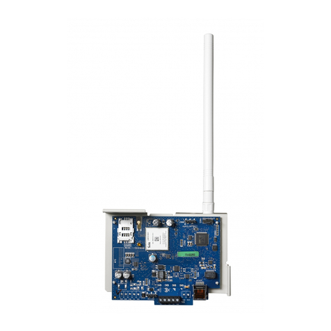
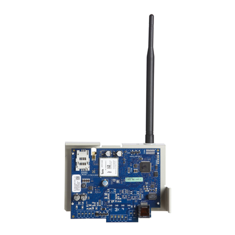
The LE4000 is a cellular communicator that sends alarm system information to a Sur-Gard System I-IP, II, III, IV or 5 receiver
through an LTE or 3G wireless network. This cellular communicator can be used with UL/ULC Listed compatible control units,
as indicated in the manufacturer's installation instructions.
The performance of the LE4000 depends greatly on cellular network coverage. Therefore, it should not be mounted without
firstperforming placement tests to determine the best location for reception (minimum of one blue/green LED ON). Optional
antenna kits – LTE-8ANT (8ft/2.4m), LTE-15ANT (15ft/4.6m), LTE-25ANT (25ft/7.6m) and LTE-50ANT (50ft/15.2m) are avail-
able.
NOTE: The LE4000 is designed to work with the Contact ID communication format as described in the SIA DC-05 standard, as
well as the SIA communications format as described in the SIA DC-03 standard. Before completing the field installation of the
alarm monitoring system please ensure communication with the supervising central station is successful by sending several
events and getting confirmation that they have been received.
Features
lPenta-Band LTE; Dual-band UMTS (BII/V) and LTE (B2/4/512/13)Radio
lAdvanced Carrier Selection
lCellular Signal Indicator
lLTE /3G / Internet communication with Sur-Gard SG-System I-IP / II / III / IV / 5
lCompatible with 4-digit or 10-digit Contact ID communication format as described in SIA DC-05 Standard and the SIA DC-
03 standard for 300 baud. Example of suitable compatible alarm panels:
DSC Models HS2128, HS2064, HS2032, HS2016, PC1864, PC1832, PC1616, PC4020.
lPanel Transmission Monitoring for up to four phone numbers
lSimulates landline
lSwitches automatically to the LTE or 3G network in the event of landline trouble (e.g., line down)
lDLS support for status, firmware updates and remote debug enable
lRemote Firmware Upgrade
lRemote Diagnostics
lCase and Wall Tamper
lPanel Format Detection
l2 Programmable Inputs
l2 Programmable Outputs
Technical Specifications
The input voltage to the LE4000 can be drawn from the UL/ULC Listed control panel or provided by an external UL/ULC Listed
power supply (with battery back-up) rated for the application (external power-limited source).
Power Supply Rating
Input Voltage Class: Class 2, power limited
Compatible External Power Adapters (2-
prong):
DSC ADP1310(W)-NAU (US) / ADP1310(W)-NA (Canada)
NOTE: For UL/ULC listed installations, the input rating for the external
power adapter is 120VAC/60Hz/0.4A.
Input Voltage/ Input Current (Nominal): 13.8VDC/700mA (when supplied by compatible external power adapter)
9-14VDC/500mA (use listed, compatible control panel or power supply)
Average Current: 40mA*
Peak Current (no battery): 180mA*
Peak Current (with battery): 350mA*
* Plus any curent draw from LE4000 + ve terminal
Battery: NiMH, rated 7.2V, 2.2Ah
Battery Charging Voltage (maximum): 9.1VDC
Battery Charging Current: 160mA
Battery Standby Time: 24 hours
NOTE: Battery must be replaced every 3-5 years.
3

Cellular
3G Bands B2, B5.
LTE Bands B2, B4, B5, B12, B13 (see See page 4)
Antenna Gain 2.0 dBi
Environmental Specifications
Operating temperature: 0°C-49°C (32°F-120°F)
Humidity: 93% RH Maximum (non-condensing)
Mechanical Specifications
Dimensions (mm): 125mm (W) x 220mm (H) x 31mm (D)
Dimensions (inches): 4.9” x 8.7” x 1.2”
Weight (without battery): 400g / 1.2oz
Simulated Telco Loop Specifications
On-Hook Voltage: 12VDC
Off-Hook Current: 24mA
Loop Current: 25mA
Loop Resistance: 600 Ohms
Table 1: Band Frequencies
Band Transmit Band (Tx) Receive Band (Rx)
LTE B2 1850 - 1910 MHz 1930 - 1990 MHz
LTE B4 1710 - 1755 MHz 2110 - 2155 MHz
LTE B5 824 - 849 MHz 869 - 894 MHz
LTE B12 698 - 716 MHz 728 - 746 MHz
LTE B13 777 - 787 MHz 746 - 756 MHz
UMTS B2 1850 - 1910 MHz 1930 - 1990 MHz
UMTS B5 824 - 840 MHz 869 - 894 MHz
4

Installing the LE4000
C24 Communications Enrollment
The LE4000 requires enrollment with C24 Communications to operate. For more information, please visit www.connect24.com,
contact C24 Communications customer service at 1-888-251-7458 (US) / 1-888-955-5583 (Canada) or contact the central sta-
tion to inquire if they are a C24 Communications Master Reseller.
NOTE: Enrollment with C24 Communications should be performed before turning on the LE4000 unit.
Before inserting or removing the SIM card, please ensure the unit is turned off.
Step 1 - Initialize the LE4000 with C24 Communications
The LE4000 can be initialized with C24 Communications by:
web - www.connect24.com
mobile - m.connect24.com
To complete enrollment,a C24 profile, installer ID/PIN (or web credentials) and the 20-digit SIM number are required.
NOTE: The SIM activation process with the cellular carrier typically takes between five and ten minutes to complete.
Step 2 - Determine the Best Signal Location
1. Remove the front cover by inserting a screwdriver into each of the slots at the bottom of the enclosure and pushing down.
2. Apply power (DC and/or battery). The LE4000 is now in Placement Test mode.
Step 2a – SIM Card is Activated.
The red LED will be on solid, the blue LED will be off and the signal strength LEDs will display the average signal strength. In
this state, the LE4000 is registered to the cellular network.
If the signal strength is too low (bottom signal LED off or flashing), the LE4000 will move to Step 3 and scan for carriers with suf-
ficient signal strength and attach to the carrier. If the LE4000 is connected to a carrier with sufficient signal strength (minimum of
bottom signal strength LED on solid), it will move to Step 4.
Step 2b – SIM Card is Not Activated
The red LED will flash, the blue LED will be off and the signal strength LEDs will display the average signal strength.
In this state, the LE4000 is unable to register to the cellular network because it is inactive. The signal strength indicated is from
any nearby cell tower (including cellular towers belonging to non-roaming partners) and does not necessarily reflect the signal
strength of the intended network. The LE4000 will remain in this state until the SIM is activated. Once the SIM is activated, the
LE4000 will move to Step 2a.
Step 3 – Carrier Scanning Due To Insufficient Signal Strength
The LE4000 will scan the surrounding cellular network and connect to the carrier to provide a signal strength of at least 7 CSQ.
When this action is being performed, all four LEDs will activate to show a scanning sequence. The LEDs will cycle from top to
bottom and then bottom to top. This cycle will continue until the LE4000 is connected to a carrier with a signal strength above 7
CSQ (minimum of bottom signal strength LED on solid). This process can take several minutes.
The carrier scanning sequence repeats until complete.
Once this is completed, the LE4000 will move to Step 4.
Step 4 - Acquire C24 Communications Programming
The red LED will be on solid and the blue LED will flash. The flashing of the blue LED indicates that the LE4000 has requested
programming from C24 Communications and is waiting for a response.
Once remote programming is completed, the blue LED will switch to solid and the LE4000 will move to Step 5.
Step 5 – Receiver Initialization
The red LED and the blue LED are both solid and the signal strength LEDs are off.
When the LE4000 sends a requestto communicate with the central station, the top signal strength LED will begin flashing.
When the central station communicates backwith the LE4000, the top signal strength LED will turn on solid.
When the LE4000 sends a requestto communicate with the next central station, the bottom signal strength LED will begin flash-
ing.
When a signal is reveived back from the central station, The bottom signal strength LED turns on solid.
If at least one of the central stations did not respond back to the communicator, the signal strength LED corresponding to that
central station will turn off. Once the initialization sequence is complete, the LE4000 will move on to steady state operation.
Step 6 - Mount the LE4000
NOTE: Ifusing an LE4000 trim plate, snap the LE4000 back plate onto the trim plate before mounting to the wall. If flush mount-
ing or using with an extension antenna, remove the provided breakaway from the trim plate prior to mounting.
1. Using the mounting holes on the LE4000 backplate, mark the four screw locations. Drill the anchor screw holes. NOTE:
Check for cable conduits and water pipes before drilling.
2. Inspect the mounting surface. Ensure that the surface is flat and will hold the wall tamper closed when mounted. Using
anchor screws(not provided), mount the cabinet to the wall.
3. Run the cables through the cable entry [13] or through the cabinet cable run knockout [15].
4. Complete the connections on the terminal blocks [12].
5. Reattach the front cover [1] securely to the cabinet.
5

LE4000 Wiring Diagram
Supervision
Relay Optional
use of PGM
output (See
Programming)
WARNING:
Incorrect connections may result in PTC failure or improper operation. Inspect wiring and ensure connections are correct before turning on.
All circuits are classified for UL installations as Power Limited/Class II Power Limited. Do not route any wiring over circuit boards. Maintain at least 1” (25.4mm) separation. A
minimum 1/4” (6.4mm) separation must be maintained at all points between Power Limited wiring and all other Non-Power Limited wiring. Route wires as indicated in the diagram.
NOTE: For ULC Commercial Burglary Installation requirements please refer to Figure 5 and to the ULC Installation Guide P/N 29002157.
Telephone Line
Connection
RJ-45
For use in dry indoor ordinary locations only. For installation refer to NFPA70, 72.
Examples of control units/Subscribers Unit or power supplies compatible models:
DSC PC1864, HS2128, PC5204, HSM2204.
Electrical Ratings: 13.8 VDC / 700 mA use ADP1310W-NAU/NA (US/CDN) and
Battery: 7.2V/2.2Ah
Electrical ratings: 9-14VDC/500mA use listed control panel or power supply
Alarm Control Panel with
Dialler Interface
(Supports Contact ID
format)
BATTERY
Sealed
Rechargeable
7.2V / 2.2Ah
RM1-UL Installations
RM1C-ULC Installations
Connect relay contacts to a zone input on the alarm control
panel for LE4000 troubles supervision (24hr-type zone)
T
I
P
R
I
N
G
Panel Aux Power or External Power Supply AUX
Output of the control panel (which can power the
communicator) shall be rated LPS (power limited). Use only
power supplies that have AUX output isolated from EGND
Typical battery charge: 30-50 mA
Recommended Model: NiMH, Rated 7.2V, 2.2Ah
Use only: Model 6PH-H-AA2200-S-D22 from Great Power.
LE4000
TIP RING T1 R1 Z1 PGM1 Z2 PGM2 DC IN
+
-
12345679
810
WARNING!
HIGH VOLTAGE.
DISCONNECT DC
POWER AND
TELEPHONE LINES
PRIOR TO SERVICING.
Incorrect connections
may result in failure
or improper operation.
}
Inputs to be connected
to dry contact outputs
from alarm control panel
(Use No. 26 AWG
wires for the
connection to PSTN)
+12V
1K5
For UL Installations, the system shall be installed in accordance with chapter 2 of the ANSI/NFPA 72 and ANSI/NFPA70. Recommended loca-
tions and wiring methods shall be in accordance with the National Electrical Code, ANSI/NFPA 70, the Standard for Installation and Classifica-
tion of Burglar and Holdup Alarm Systems, UL 681, and the Standard for Central-Station Alarm Services, UL 827.
For ULC Installations, the recommended locations and wiring methods shall be in accordance with CSA C22.1, Canadian Electrical Code, Part
I, Safety Standard for Electrical Installations; CAN/ULC-S302, Installation and Classification of Burglar Alarm Systems for Financial and Com-
mercial Premises, Safes and Vaults; and CAN/ULC-S301, Standard for Central and Monitoring Station Burglar Alarm Systems and the Stan-
dard for the Installation of Residential Fire Warning Systems, CAN/ULC-S540. Do not install the equipment in places where the signal strength
does not meet the minium recomended signal strength level. Do not run zone inputs and T1/R1 wiring along AC wires or other circuits with high
frequency signals in order to reduce possibility of interference and false alarms.
6

MODIFICATION STATEMENT
DigitalSecurity Controls has not approved any changes or modifications to this device by the user.
Any changes or m odif icat ions could void the user’s authority t o operate the equipment.
Digital Security Controls n’approuve aucune modification apportée à l’appareil par l’utilisateur,
quelle qu’en soit la nature. Tout changement ou modificat ion peuvent annuler le droit d’utilisation de
l’appareilpar l’utilisateur.
INTERFERENCE STATEMENT
This device com plies with Part 15 of the FCC Rules and ISED Canada licence-exempt RSS st and-
ard(s). Operation is subject t o the f ollowing t wo conditions: (1) t his device m ay not cause inter-
ference, and (2) this device m ust accept any interference, including interf erence that may cause
undesired operation of t he device.
Le présent appareil est conforme aux CNR d'ISED Canada applicables aux appareils radio
exem pts de licence. L'exploit ation est aut orisée aux deux conditions suivantes : (1) l'appareil ne
doit pas produire de brouillage, et (2) l'utilisateur de l'appareil doit accepter tout brouillage radi-
oélect rique subi, même si le brouillage est suscept ible d'en comprom ett re le fonct ionnement .
WIRELESS NOTICE
This equipment complies with FCC and ISED Canada radiation exposure limits set forth for an
uncontrolled environment. The antenna should be inst alled and operated with minimum distance of
20 cm between t he radiator and your body. This transmitt er m ust not be co-located or operat ing in
conjunct ion with any ot her ant enna or transm it ter.
Cet appareilest conforme aux limites d'exposition aux rayonnements de la ISED Canadapour un
environnement non contrôlé. L'antenne doit êt re installé de façon à garder une dist ance minimale
de 20 centimètres ent re la source de rayonnements et vot re corps. L'émet teur ne doit pas êt re
colocalisé ni fonctionner conjointem ent avec à aut re antenne ou autre émett eur.
Antenna gain must be below/Gain de l'antenne doit être ci-dessous:
Frequency Band/Bande de fréquence LE4000
GSM 850 / FDD V 6.21 dBi
PCS 1900 / FDD II 3.76 dBi
LTE B2 2.76 dBi
LTE B4 2.82 dBi
LTE B5/ B12/ B13 2.45 dBi
FCC CLASS B DIGITAL DEVICE NOTICE
This equipment has been tested and found to comply with t he limits f or a Class B digital device, pur-
suant to part 15 of the FCC Rules. These limits are designed to provide reasonable protection
against harm ful interference in a residential inst allation. This equipment generates uses and can
radiate radio f requency energy and, if not installed and used in accordance with the inst ructions,
may cause harmf ul interf erence t o radio comm unications. However, there is no guarant ee t hat
interference will not occur in a part icular inst allat ion. If this equipment does cause harmful inter-
ference to radio or television recept ion, which can be determ ined by turning the equipment off and
on, t he user is encouraged to t ry t o correct the interf erence by one or more of the f ollowing m eas-
ures:
• Reorient or relocate the receiving antenna.
• Increase the separation between the equipment and receiver.
• Connect t he equipment into an outlet on a circuit different from t hat to which t he receiver is con-
nected.
• Consult t he dealer or an experienced radio/TV t echnician for help.
FCC ID: F5317LE4000
LE4000 Product Identifier US: F5317MO00ALE4000
REN: 0.0A
USOC Jack: RJ-31X
WARNING: To satisfy FCC RF exposure requirements for mobile transmitting devices, a
separation distance of 20cm or more must be maintained between the antenna of this
device and persons during device operation.
Telephone Connection Requirements
A plug and jack used t o connect this equipment t o the prem ises wiring and telephone network must
com ply with t he applicable FCC Part 68 rules and requirements adopted by t he ACTA. A compliant
telephone cord and modular plug is providedwith this product. It is designed to be connected to a
com patible modular jack that is also compliant. See inst allation inst ruct ions for det ails.
Ringer Equivalence Number (REN)
The REN is used to determine the number of devices that may be connected to a telephone line.
Excessive RENs on a t elephone line may result in the devices not ringing in response t o an incom-
ing call.
In most but not all areas, the sum of RENs shouldnot exceed five (5.0). To be certainof the num-
ber of devices that may be connected to a line, as determined by the totalRENs, contact the local
Telephone Company. For product s approved after July 23, 2001, t he REN f or this product is part of
the product identifier that has t he form at. US: AAAEQ##TX XXX. The digit s represented by ## are
the REN without a decimal point (e.g., 03 is a RE N of 0.3). For earlier product s, t he RE N is sep-
arately shown on the label.
Incidence of Harm
If this equipment LE4000 causes harm t o the telephone network, the t elephone com pany will notify
you in advance that temporary discontinuance of service may be required. B ut if advance notice is
not pract ical, the Telephone Company willnot if y the cust omer as soon as possible. Also, you will be
advised of your right to filea complaint with the FCCif you believe it is necessary.
Changes in Telephone Company Equipment or Facilities
The Telephone Company m ay make changes in its f acilities, equipment , operat ions or procedures
that could affect the operation of the equipment. If this happens the Telephone Company will
provide advance notice in order f or you t o make necessary m odif icat ions t o maintain uninterrupted
service.
Equipment Maintenance Facility
If trouble is experienced with t his equipment for repair or warrant y information, please contact the
facility indicated below. If the equipment is causing harm to the telephonenetwork, the Telephone
Company m ay request that you disconnect t he equipment until t he problem is solved. This equip-
ment is of a type that is not intended to be repaired by the enduser.
DSC c/o APL Logistics, 757 Douglas HillRd., Lithia Springs, GA 30122
Additional Information
Connection to party line service is subject to state tariffs. Contact the state public utility com-
mission, public service com mission or corporat ion comm ission for inform ation. A larm dialling equip-
ment must be able to seize t he telephone line and place a call in an emergency situation. I t m ust be
ableto do this even if other equipment (telephone, answering system, computer modem, etc.)
already has the telephone line in use. To do so, alarm dialling equipment m ust be connect ed to a
properly inst alled RJ-31X jack that is elect rically in series with and ahead of all ot her equipment
attached to the same t elephone line. Proper installation is depicted in the figure below. If you have
any questions concerning these instruct ions, you should consult your t elephone company or a qual-
ified installer about installing t he RJ-31X jack and alarm dialling equipment for you.
Industry Canada Compliance Statement
This Equipment meets the applicable Industrial, Scientific and Economic Development (ISED)
Canada Terminal Equipment Technical Specifications. This is confirmed by t he registration num-
ber. The abbreviation, I C, bef ore t he regist ration number signifies t hat registration was perform ed
based on a Declaration of Conf orm it y indicat ing t hat I SED Canada technical specifications were
met. It does not imply that that ISED Canada approved the equipment. The Ringer Equivalence
Number (REN) for this terminal equipment is 0.0. The REN assignedto each terminal equipment
provides an indication of t he maximum number of t erminals allowed t o be connected t o a telephone
interface. The termination on an interface may consist of any combination of devices subject only
to the requirement t hat t he sum of t he Ringer Equivalence Numbers of all devices does not exceed
5.
IC:160A-LE4000
Cet équipement est conforme aux spécifications techniques applicables aux équipements ter-
minaux d'ISED Canada. Ceci est confirmé par le numéro d'enregistrement. L'abréviation IC
précédant le numéro d'enregistrement signifie que l'enregistrement a été ef fectué sur la base de la
Déclaration de conformité indiquant que le produit est conforme aux spécifications techniques
d'ISED Canada. Ceci n'implique pas que le produit ait été approuvé par I SED Canada.
Le nombre équivalent de sonneries (REN) de cet appareil terminal est 0.0. Le REN attribué à
chaque équipement term inal fournit une indication sur le nombre m aximum de term inaux pouvant
être connect és sur une interface téléphonique. La terminaison sur une interf ace peut const ituer en
n'import e quelle com binaison d'appareils, à la condition seulement que la somme des Nombres équi-
valents de sonneries de tous les appareils ne soit pas supérieure à 5.
CAN I CES-3 (B) / NMB-3 (B)
The term “IC: ” before t he radio cert ification number only signif ies t hat I SED Canada t echnical spe-
cificat ions were met .
NIST Validation of encryption algorithm AES128 (cert if icate No. 5011 available at NIST website).

Digital Security Controls warrant s the original purchaser that for a period of twelve months f rom
the date of purchase, t he product shall be free of defects in mat erials and workmanship under nor-
mal use. During the warranty period, Digit alSecurity Cont rols shall, at its option, repair or replace
any defective product upon return of the product to its factory, at no charge for labour and mater-
ials. Any replacement and/or repaired parts are warranted for the remainder of the original war-
ranty or ninety (90) days, whichever is longer. Theoriginal purchaser must promptly notify Digital
Security Controls in writing that there is defect in materialor workmanship, such written notice to
be received in all events prior to expiration of the warrant y period. There is absolutely no warranty
on software and allsoftware products are soldas a user license under the terms of the software
license agreement included with the product. The Customer assumes all responsibility for the
proper select ion, inst allation, operat ion and m aint enance of any products purchased f rom DSC.
Cust om product s are only warranted t o t he ext ent that they do not f unct ion upon delivery. I n such
cases, DSC can replace or credit at its opt ion.
International Warranty
The warranty for internationalcustomers is the same as for any customer within Canadaand the
United States, with the exception that DigitalSecurity Controls shallnot be responsible for any cus-
toms f ees, taxes, or VAT that m ay be due.
Warranty Procedure
To obtain service under this warranty, please return the item (s) in question to the point of pur-
chase. Allauthorized distributors and dealers have a warranty program. Anyone returning goods t o
DigitalSecurity Controls must first obtain an authorization number. Digital Security Controls will
not accept any shipment whatsoever for which prior authorizationhas not been obtained.
Conditions to Void Warranty
This warranty applies only to defects in part s and workmanship relating to norm al use. It does not
cover:
ldamage incurred in shipping orhandling;
ldamage caused bydisaster such asfire, flood, wind, earthquake orlightning;
ldamage due to causesbeyond the controlof DigitalSecurityControlssuch as
excessive voltage, mechanicalshockor water damage;
ldamage caused byunauthorized attachment, alterations, modifications or
foreign objects;
ldamage caused byperipherals(unlesssuch peripheralswere supplied by
DigitalSecurityControls);
ldefectscaused byfailure to provide a suitable installation environment forthe
products;
ldamage caused byuse of the productsfor purposesother than those for
which it was designed;
ldamage fromimproper maintenance;
ldamage arising out of anyotherabuse, mishandling or improper application
of the products.
Items Not Covered by Warranty
In additionto the items which voidthe Warranty, the following items shall not be covered by War-
ranty: (i) f reight cost t o the repair centre; (ii) product s which are not identified with DSC's product
labeland lot number or serialnumber; (iii) products disassembled or repaired in such a manner as to
adversely affect performance or prevent adequate inspection or testing to verify any warranty
claim. Access cards or tags returned f or replacement under warranty will be credited or replaced at
DSC's option. Products not covered by this warranty, or otherwise out of warranty due to age, mis-
use, or damage shallbe evaluated, and a repair estimate shall be provided. No repair work will be
performed until a valid purchase order is received from the Customer and a Ret urn M erchandise
Authorisat ion number (RMA) is issued by DS C's Cust omer S ervice.
DigitalSecurity Controls’s liability for failure to repair the product under this warranty after a reas-
onable number of attem pts will be limited to a replacem ent of t he product, as t he exclusive remedy
for breach of warranty. Under no circumstances shall Digital Security Controls be liable f or any spe-
cial, incidental, or consequential damages based upon breach of warranty, breach of cont ract, neg-
ligence, strict liability, or any other legaltheory. Such damages include, but are not limited to, loss
of profits, loss of the product or any associated equipment, cost of capital, cost of substitute or
replacement equipment, facilities or services, down time, purchaser’s time, the claims of third
parties, including custom ers, and injury to property. The laws of some jurisdict ions limit or do not
allow t he disclaimer of consequentialdamages. I f t he laws of such a jurisdict ion apply t o any claim
by or against DSC, t he limitations and disclaimers cont ained here shall be to t he great est ext ent
permitted by law. Some states do not allow the exclusion or lim it ation of incidental or consequential
damages, so that the above m ay not apply t o you.
Disclaimer of Warranties
This warranty contains the entire warranty and shall be in lieu of any and all other war-
ranties, whether expressed or implied (including all implied warranties of merchantability
or fitness for a particular purpose) And of all other obligations or liabilities on the part of
Digital Security Controls Digital Security Controls neither assumes responsibility for, nor
authorizes any other person purporting to act on i ts behalf to modify or to change this war-
ranty, nor to assume for it any other warranty or liability concerning this product.
This disclaimer of warranties and limited warranty are governed by the laws of the
province of Ontario, Canada.
DigitalSecurity Controls recommends that the entire system be completely tested on a regular
basis. However, despite f requent t esting, and due to, but not limited t o, criminal tampering or elec-
trical disruption, it is possible for t his product t o fail to perform as expected.
Installer’s Lockout
Any products ret urned to DSC which have t he Installer’s Lockout option enabled and exhibit no
other problems will be subject t o a service charge.
Out of Warranty Repairs
Digital Security Controls will at its option repair or replace out- of-warranty products which are
returned to its factory according to the following conditions. Anyone returning goods to Digital
Security Controls must first obtain an authorization number. Digital Security Controls will not
accept any shipment whatsoever for which prior authorizationhas not been obtained.
Product s which Digital Security Controls det ermines t o be repairable will be repaired and ret urned.
A set fee which Digital Security Controls has predeterm ined and which m ay be revised from t im e to
time, will be charged for each unit repaired.
Products which Digital Security Controls determines not to be repairable will be replaced by the
nearest equivalent product available at that time. The current market price of the replacement
product will be charged for each replacem ent unit.
© 2017 Tyco Security Products. All Rights Reserved.
Tech Support: 1-800-387-3630 (Canada & U.S.) or 905-760-
3000
www.dsc.com
The trademarks, logos, and service marks displayed on t his document are registered in the United
States [or other countries]. Any misuse of the trademarks is strictly prohibited and Tyco will
aggressively enf orce its intellect ual property rights to t he fullest extent of the law, including pursuit
of criminal prosecution wherever necessary. All trademarks not owned by Tyco are t he propert y of
their respect ive owners, and are used with perm ission or allowed under applicable laws.
Product offerings and specifications are subject to change without notice. Actual products may
vary f rom photos. Not all product s include all features. Availability varies by region; contact your
sales representative.
Warranty
Other manuals for LE4000
2
Table of contents
Other DSC Cell Phone manuals

DSC
DSC neo Power Series User manual

DSC
DSC 3G4010 User manual

DSC
DSC GS3055-IG User manual

DSC
DSC 3g4000 User manual

DSC
DSC IT-410 Assembly instructions

DSC
DSC TL260GS User manual

DSC
DSC Skyroute CL3050 Operating instructions

DSC
DSC 3G4010CF User manual

DSC
DSC 3G2060 User manual

DSC
DSC Skyroute CL3050 ver 1.2 Operating instructions

DSC
DSC TL280 User manual

DSC
DSC TL280R Operating and maintenance instructions

DSC
DSC GS3125 Series User manual

DSC
DSC GS2060-SM User manual

DSC
DSC T-Link TL300 User manual

DSC
DSC TL280R User manual

DSC
DSC 3G4010 User manual

DSC
DSC PowerSeries Neo TL280LER User manual

DSC
DSC 3G2075 User manual

DSC
DSC PowerSeries Neo 3G2080E User manual