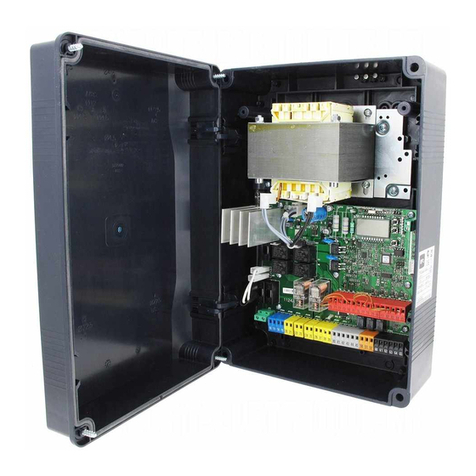
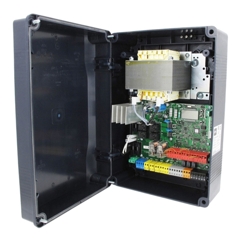
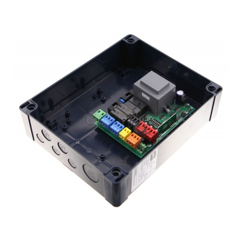
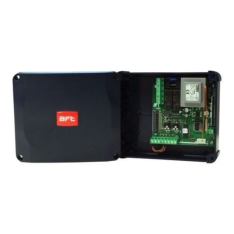
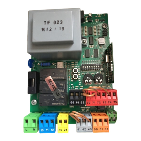
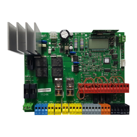
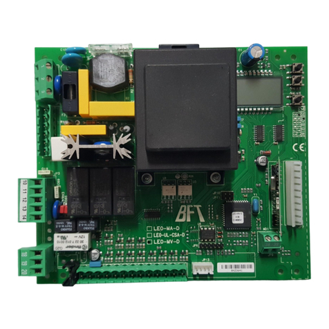
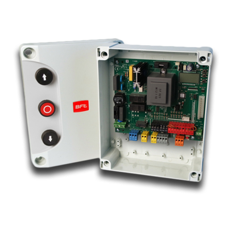
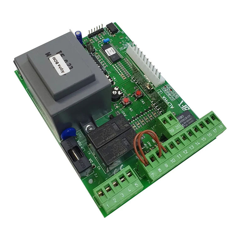
BFT PERSEO CBD 230.P SD User manual

PERSEO CBD 230.P SD
D811944_04 17-1-13
ISTRUZIONI DI INSTALLAZIONE
INSTALLATION MANUAL
INSTRUCTIONS D’INSTALLATION
MONTAGEANLEITUNG
INSTRUCCIONES DE INSTALACION
INSTRUÇÕES DE USO E DE INSTALAÇÃO
PERSEO CBD 230.P SD
Attenzione! Leggere attentamente le“Avvertenze” all’interno! Caution! Read“Warnings”inside carefully! Attention! Veuillez lire attentivement les Avertissements qui se trouvent à l’intérieur! Achtung! Bitte lesen Sie
aufmerksam die„Hinweise“ im Inneren! ¡Atención¡ Leer atentamente las“Advertencias”en el interior! Let op! Lees de“Waarschuwingen”tigre aan de binnenkant zorgvuldig!
QUADRO COMANDO
CONTROL PANEL
CENTRALE DE COMMANDE
SELBSTÜBERWACHENDE STEUERUNG
CUADRO DE MANDOS
QUADRO DE COMANDO
8
027908 422187
88
www.torautomatic.hr

2 - PERSEO CBD 230.P SD
INSTALLAZIONE VELOCE-QUICK INSTALLATION-INSTALLATION RAPIDE
SCHNELLINSTALLATION-INSTALACIÓN RÁPIDA -
INSTALAÇÃO RÁPIDA
A
C
B
Connettore Trasformatore/
Transformer Connector/
Connecteur Transformateur/
SteckverbindungTransformator/
Conector Transformador/
Conector Transformador
PREDISPOSIZIONE TUBI, TUBE ARRANGEMENT,
PRÉDISPOSITION DES TUYAUX, VORBEREITUNG DER LEITUNGEN,
DISPOSICIÓN DE TUBOS, DISPOSIÇÃO DOS TUBOS
2x1mm2
4x1mm2
16x1mm2
3x1mm2
3x1mm2
3x1mm2
2x1,5mm2
RG58
3x1,5mm2
126,08
F3 250mA T
Display + Tasti programmazione/
Display + programming keys
Acheur + touches programmation/
Display + Programmierungstaten/
Pantalla + botones
programación/
Display mais teclas de programação
Ricevente radio integrata/
Built-in radio-receiver/
Récepteur radio intégré/
Integrierter Funkempfänger/
Receptor radio incorporado /
Receptor rádio integrado
Connettore programmatore palmare/
Handheld programmer connector/
Connecteur programmeur palmaire/
Steckverbindung
Handprogramiereinheit/
Conector programador portátil/
Conector programador palmar
START
BAT
+
EF
SHIELD
ANT
J10
220-230V ~
50-60Hz
J2 J5 J7 J9
230V 40W
230V 40W
230V 40W
Max 24V 0,5A
Max 24V 0,5A
NO NO NO NO NONC NC
24 Vac 1A Max
24 Vac 0,1A Max
24 Vac 0,1A Max
200,05 mm
275,5 mm
126,08 mm
FCA
MOT
8. 8.
F2 1A T
F1 6.3F 230V F3 250mA T
www.torautomatic.hr

PERSEO CBD 230.P SD - 3
x 2s
G6
G8
F +
.....H6, H8, D5.....
+
F +
+-
+-
Salvataggio e Uscita / Save and Exit / Sauvegarde et Sortie /
Speichern und Verlassen/ Guardado y Salida /
Guardar e Sair
+
SELEZIONE DISSUASORE - SELECT BOLLARD -
SÉLECTION BORNE ESCAMOTABLE
AUSWAHL POLLER - SELECCIÓN DISUASOR - SELEÇÃO DISSUASOR
CONNESSIONE PROGRAMMATORE - PROGRAMMER CONNECTION -
CONNEXION PROGRAMMATEUR - ANSCHLUSS PROGRAMMIEREINHEIT -
CONEXIÓN PROGRAMADOR - CONEXÃO PROGRAMADOR
D
E
8. 8.
-+
F
LEGENDA - KEY - LÉGENDE - LEGENDE - LEYENDA - LEGENDA
g6
Non disponibile, Not available, Pas disponible, Nicht verfügbar, No disponible,
Não disponível
G8
Non disponibile, Not available, Pas disponible, Nicht verfügbar, No disponible,
Não disponível
H8
Non disponibile, Not available, Pas disponible, Nicht verfügbar, No disponible,
Não disponível
d5
STOPPY MBB 219-500 C.
D7
STOPPY MBB 219-700 C.
E5
Non disponibile, Not available, Pas disponible, Nicht verfügbar, No disponible,
Não disponível
E7
Non disponibile, Not available, Pas disponible, Nicht verfügbar, No disponible,
Não disponível
F7
Non disponibile, Not available, Pas disponible, Nicht verfügbar, No disponible,
Não disponível
Selezionare frequenza di rete tramite parametro Ht.
Select mains frequency using Ht parameter.
Sélectionner la fréquence du secteur avec le paramètre Ht.
Wählen Sie die Netzfrequenz mit dem Parameter Ht.
Seleccionar frecuencia de red mediante parámetro Ht.
Selecionar a frequência de rede mediante o parâmetro Ht.
LEGENDA - KEY - LÉGENDE - LEGENDE - LEYENDA - LEGENDA
+Scorri avanti / Scroll forward / Déler vers l’avant / Bildlauf vor /
Desplazar hacia delante / Navegar para frente
-Scorri indietro / Scroll back /Déler vers l’arrière/ Bildlauf zurück
/ Desplazar hacia atrás / Navegar para trás
F++x2s Accesso al menu / Call up menu / Accès au menu / Zugang zum
Menü / Acceso al menú / Acesso ao menu
F ++Salvataggio e uscita / Save and exit / Sauvegarde et sortie /
Speichern und Verlassen / Guardado y salida / Guardar e sair
ITALIANO ENGLISH FRANÇAIS DEUTSCH ESPAÑOL
PORTUGUÊS

4 - PERSEO CBD 230.P SD
D811944_04
4 - PERSEO CBD.P
FCA1
NO
FCA4
NO
FCA3
NO
FCA2
NO
BAT
+
EF
SHIELD
ANT
J10
220-230V ~
50-60Hz
J2 J5 J7 J9
230V 40W
230V 40W
230V 40W
Cap 1 Cap 2 Cap 3 Cap 4
Max 24V 0,5A
Max 24V 0,5A
NO NO NO NO NC NC
24 Vac 1A Max
24 Vac 0,1A Max
24 Vac 0,1A Max
STOPPY
1
STOPPY
2
STOPPY
3
STOPPY
4
M1 M2 M3 M4
LED1 LED2 LED3 LED4
BZ1 BZ2 BZ3 BZ4
EF1 EF2 EF3 EF4
F
2nd CH
RX

PERSEO CBD 230.P SD - 5
D811944_04
ACCESSO AI MENU Fig. 1
x 2s
F
F
F
F
+ -
F
+ - F +
F
+ -
F
+ -
F
+ -
F
+ -
F
F
F
F
F +
+ -
F
+ -
F
+ -
F
F
F
F
F
F +
USCITA
P3.XX
P3.2
P3.1
p1.1
p1.2
p1.xx
p2.1
p2.2
p2.xx
ST
/
/
/
/
+
/
/
/
+
+
/
/
8. 8.
-+
PROGRAMMAZIONE DI 1° LIVELLO
PROGRAMMAZIONE DI 2° LIVELLO
PROGRAMMAZIONE DI 3° LIVELLO
F
00-
01-
02-
00-
01-
02-
00-
01-
02-
00-
01-
02-
00-
01-
02-
00-
01-
02-
00-
01-
02-
00-
01-
02-
00-
01-
02-
l Conferma
+ Scorri avanti
- Scorri indietro
Fx2s Accesso alla programmazione
F ++ Livello di programmazione successivo
PERSEO CBD 230.P SD - 5
Codice
diagnoistica
Descrizione Note
01 Inattivo
02 Apertura
03 Stop necorsa apertura
04 Stop apertura
05 Chiusura
06 Stop necorsa chiusura
07 Stop chiusura
08 Stop per intervento fotocellula
09 Apertura per intervento fotocellula
10 Pausa intervento fotocellula
14 Raggiunto tempo di lavoro massimo in apertura
15 Raggiunto tempo di lavoro massimo in chiusura
ITALIANO

6 - PERSEO CBD 230.P SD
D811944_04
AVVERTENZE PER L’INSTALLATORE
Tutto quello che non è espressamente previsto nel manuale d’in-
stallazione, non è permesso. ll buon funzionamento dell’operatore
è garantito solo se vengono rispettati i dati riportati. La ditta non
risponde dei danni causati dall’inosservanza delle indicazioni ripor-
tate in questo manuale.
Lasciandoinalteratelecaratteristicheessenzialidel prodotto,laDitta
si riserva di apportare in qualunque momento le modiche che essa
ritiene convenienti per migliorare tecnicamente, costruttivamente
e commercialmente il prodotto, senza impegnarsi ad aggiornare la
presente pubblicazione.
ATTENZIONE! Importanti istruzioni di sicurezza. Leggere e seguire atten-
tamente tutte le avvertenze e le istruzioni che accompagnano il prodotto
poiché un’installazione errata può causare danni a persone, animali o cose.
Leavvertenzeeleistruzionifornisconoimportantiindicazioniriguardantila
sicurezza, l’installazione, l’uso e la manutenzione. Conservare le istruzioni
per allegarle al fascicolo tecnico e per consultazioni future.
SICUREZZA GENERALE
Questo prodotto è stato progettato e costruito esclusivamente per l’utilizzo
indicato in questa documentazione. Usi diversi da quanto indicato potrebbero
essere causa di danni al prodotto e di pericolo.
-Gli elementicostruttividella macchinael’installazionedevonoessereinaccordo
con le seguenti Direttive Europee, ove applicabili: 2004/108/CE, 2006/95/CE,
2006/42/CE, 89/106/CE, 99/05/CE e loro modiche successive. Per tutti i Paesi
extra CEE, oltre alle norme nazionali vigenti, per un buon livello di sicurezza è
opportuno rispettare anche le norme citate.
-La Ditta costruttrice di questo prodotto (di seguito “Ditta”) declina qualsiasi
responsabilità derivante da un uso improprio o diverso da quello per cui è
destinato e indicato nella presente documentazione nonché dall’inosservanza
della BuonaTecnica nella costruzione delle chiusure (porte, cancelli, ecc.) e dalle
deformazioni che potrebbero vericarsi durante l’uso.
-L’installazione deve essere eseguita da personale qualicato (installatore profes-
sionale, secondo EN12635), nell’osservanza della Buona Tecnica e delle norme
vigenti.
-Prima di installare il prodotto apportare tutte le modiche strutturali relative
alle realizzazione dei franchi di sucurezza a alla protezione o segregazione di
tutte le zone di schiacciamento, cesoiamento, convogliamento e di pericolo in
genere, secondo quanto previsto dalle norme EN 12604 ed 12453 o eventuali
normelocalidi installazione.Vericareche lastrutturaesistenteabbia inecessari
requisiti di robustezza e stabilità.
-Prima di iniziare l’installazione vericare l’integrità del prodotto.
-La Ditta non è responsabile della inosservanza della Buona Tecnica nella costru-
zione e manutenzione degli inssi da motorizzare, nonché delle deformazioni
che dovessero intervenire nell’utilizzo.
-Vericare che l’intervallo di temperatura dichiarato sia compatibile con il luogo
destinato all’installazione dell’automazione.
-Non installare questo prodotto in atmosfera esplosiva: la presenza di gas o fumi
inammabili costituisce un grave pericolo per la sicurezza.
- Togliere l’alimentazione elettrica, prima di qualsiasi intervento sull’impianto.
Scollegare anche eventuali batterie tampone se presenti.
-Primadicollegarel’alimentazioneelettrica,accertarsicheidatiditargacorrispon-
dano ai quelli della rete di distribuzione elettrica e che a monte dell’impianto
elettrico vi siano un interruttore dierenziale e una protezione da sovracorrente
adeguati.Prevederesullaretedialimentazionedell’automazione,uninterruttore
ounmagnetotermicoomnipolarecondistanza diaperturadeicontatticonforme
a quanto previsto dalle norme vigenti.
-Vericare che a monte della rete di alimentazione, vi sia un interruttore dieren-
ziale con soglia non superiore a 0.03A e a quanto previsto dalle norme vigenti.
-Vericare che l’impianto di terra sia realizzato correttamente: collegare a terra
tutte le parti metalliche della chiusura (porte, cancelli, ecc.) e tutti i componenti
dell’impianto provvisti di morsetto di terra.
-L’installazione deve essere fatta utilizzando dispositivi di sicurezza e di comandi
conformi alla EN 12978 e EN12453.
-Leforzediimpattopossonoessereridottemediantel’utilizzodibordideformabili.
-Nel caso in cui le forze di impatto superino i valori previsti dalle norme, applicare
dispositivi elettrosensibili o sensibili alla pressione.
-Applicaretuttii dispositivi disicurezza(fotocellule,costesensibili,ecc.) necessari
a proteggere l’area da pericoli di impatto, schiacciamento, convogliamento,
cesoiamento. Tenere in considerazione le normative e le direttive in vigore,
i criteri della Buona Tecnica, l’utilizzo, l’ambiente di installazione, la logica di
funzionamento del sistema e le forze sviluppate dall’automazione.
-Applicare i segnali previsti dalle normative vigenti per individuare le zone
pericolose (i rischi residui). Ogni installazione deve essere identicata in modo
visibile secondo quanto prescritto dalla EN13241-1.
- Successivamente al completamento dell’installazione, applicare una targa
identicativa della porta/cancello
-Questo prodotto non può essere installato su ante che incorporano delle porte
(a meno che il motore sia azionabile esclusivamente a porta chiusa).
-Se l’automazione è installata ad una altezza inferiore a 2,5 m o se è accessibile,
è necessario garantire un adeguato grado di protezione delle parti elettriche e
meccaniche.
-Installare qualsiasi comando sso in posizione tale da non causare pericoli e
lontano da parti mobili. In particolare i comandi a uomo presente devono essere
posizionati in vista diretta della parte guidata, e, a meno che non siano a chiave,
devono essere installati a una altezza minima di 1,5 m e in modo tale da non
essere accessibili al pubblico.
-Applicare almeno un dispositivo di segnalazione luminosa (lampeggiante) in
posizione visibile, ssare inoltre alla struttura un cartello di Attenzione.
-Fissareinmodopermanenteunaetichettarelativaalfunzionamentodellosblocco
manuale dell’automazione e apporla vicino all’organo di manovra.
-Assicurarsi che durante la manovra siano evitati o protetti i rischi meccanici ed
in particolare l’impatto, lo schiacciamento, il convogliamento, il cesoiamento tra
parte guidata e parti circostanti.
-Dopo aver eseguito l’installazione, assicurarsi che il settaggio dell’automazione
motore sia correttamente impostato e che i sistemi di protezione e di sblocco
funzionino correttamente.
-Usare esclusivamente parti originali per qualsiasi manutenzione o riparazione.
La Ditta declina ogni responsabilità ai ni della sicurezza e del buon funziona-
mento dell’automazione se vengono impiegati componenti di altri produttori.
-Non eseguire alcuna modica ai componenti dell’automazione se non espres-
samente autorizzata dalla Ditta.
-Istruirel’utilizzatoredell’impiantoperquantoriguardaglieventualirischiresidui,
i sistemi di comando applicati e l’esecuzione della manovra apertura manuale
in caso di emergenza: consegnare il manuale d’uso all’utilizzatore nale.
-Smaltireimateriali diimballo(plastica, cartone,polistirolo,ecc.)secondoquanto
previstodalle norme vigenti. Non lasciarebuste di nylonepolistirolo alla portata
dei bambini.
COLLEGAMENTI
ATTENZIONE! Per il collegamento alla rete utilizzare: cavo multipolare di sezione
minima 5x1,5mm2o 4x1,5mm2per alimentazioni trifase oppure 3x1,5mm2per
alimentazioni monofase (a titolo di esempio, il cavo può essere del tipo H05VV-F
con sezione 4x1.5mm2). Per il collegamento degli ausiliari utilizzare conduttori
con sezione minima di 0,5 mm2.
-Utilizzare esclusivamente pulsanti con portata non inferiore a 10A-250V.
-I conduttori devono essere vincolati da un ssaggio supplementare in prossi-
mità dei morsetti (per esempio mediante fascette) al ne di tenere nettamente
separate le parti in tensione dalle parti in bassissima tensione di sicurezza.
-
Il cavo di alimentazione, durante l’installazione, deve essere sguainato in modo da
permettereilcollegamentodelconduttorediterraall’appropriatomorsettolasciando
però i conduttori attivi il più corti possibile. Il conduttore di terra deve essere l’ultimo
a tendersi in caso di allentamento del dispositivo di ssaggio del cavo.
ATTENZIONE! i conduttori a bassissima tensione di sicurezza devono essere
sicamente separati dai conduttori a bassa tensione.
L’accessibilità alle parti in tensione deve essere possibile esclusivamente per il
personale qualicato (installatore professionale)
VERIFICA DELL’AUTOMAZIONE E MANUTENZIONE
Primadirenderedenitivamenteoperatival’automazione,edurantegliinterventi
di manutenzione, controllare scrupolosamente quanto segue:
-Vericare che tutti i componenti siano ssati saldamente;
-Vericare l’operazione di avvio e fermata nel caso di comando manuale.
-Vericare la logica di funzionamento normale o personalizzata.
-
Solo per cancelli scorrevoli: vericare il corretto ingranamento cremagliera -
pignone con un gioco di 2 mm lungo tutta la cremagliera; tenere la rotaia di
scorrimento sempre pulita e libera da detriti.
-Solo per cancelli e porte scorrevoli: vericare che il binario di scorrimento del
cancello sia lineare, orizzontale e le ruote siano idonee a sopportare il peso del
cancello.
-Solo per cancelli scorrevoli sospesi (Cantilever): vericare che non ci sia abbas-
samento o oscillazione durante la manovra.
-Solo per cancelli a battente: vericare che l’asse di rotazione delle ante sia
perfettamente verticale.
- Solo per barriere: prima di aprire la portina la molla deve essere scarica
(asta verticale).
-Controllareilcorrettofunzionamentodituttiidispositividisicurezza(fotocellule,
coste sensibili, ecc) e la corretta regolazione della sicurezza antischiacciamento
vericando che il valore della forza d’impatto misurato nei punti previsti dalla
norma EN 12445, sia inferiore a quanto indicato nella norma EN 12453.
-Leforzediimpattopossonoessereridottemediantel’utilizzodibordideformabili.
-Vericare la funzionalità della manovra di emergenza ove presente.
-Vericarel’operazionediaperturaechiusuraconidispositividicomandoapplicati.
-Vericare l’integrità delle connessioni elettriche e dei cablaggi, in particolare lo
stato delle guaine isolanti e dei pressa cavi.
-Durante la manutenzione eseguire la pulizia delle ottiche delle fotocellule.
-Peril periodo difuoriservizio dell’automazione,attivarelo sbloccodiemergenza
(vedi paragrafo “MANOVRA DI EMERGENZA”) in modo da rendere folle la parte
guidata e permettere così l’apertura e la chiusura manuale del cancello.
-Se il cavo di alimentazione è danneggiato, esso deve essere sostituito dal co-
struttore o dal suo servizio di assistenza tecnica o comunque da una persona
con qualica similare, in modo da prevenire ogni rischio.
-Se si si installano dispositivi di tipo “D” (come deniti dalla EN12453), collegati
in modalità non vericata, prescrivere una manutenzione obbligatoria con
frequenza almeno semestrale.
ATTENZIONE!
Ricordarsichelamotorizzazioneèunafacilitazionedell’usodelcancello/portaenon
risolveproblemiadifettiedecienzedi installazioneodi mancatamanutenzione.
DEMOLIZIONE
L’eliminazione dei materiali va fatta rispettando le norme vigenti. Nel caso di
demolizione dell’automazione non esistono particolari pericoli o rischi derivanti
dall’automazione stessa.
Èopportuno,in caso direcuperodeimateriali, che venganoseparati pertipologia
(parti elettriche - rame - alluminio - plastica - ecc.).
SMANTELLAMENTO
Nelcasol’automazionevengasmontataperesserepoirimontatainaltrositobisogna:
-Togliere l’alimentazione e scollegare tutto l’impianto elettrico.
-Togliere l’attuatore dalla base di ssaggio.
-Smontare tutti i componenti dell’installazione.
-Nel caso alcuni componenti non possano essere rimossi o risultino danneggiati,
provvedere alla loro sostituzione.
LA DICHIARAZIONE DI CONFORMITÀ PUÒ ESSERE CONSULTATA SUL SITO:
WWW.BFT.IT NELLA SEZIONE PRODOTTI.
AVVERTENZE PER L’INSTALLATORE D811766_08

PERSEO CBD 230.P SD - 7
D811944_04
1) GENERALITÁ
Il quadro comando PERSEO CBD 230.P SD viene fornito dal costruttore con
settaggio standard. Qualsiasi variazione, deve essere impostata mediante il
programmatore a display incorporato.
Supporta completamente il protocollo EELINK radio.
Le caratteristiche principali sono:
- Controllo no a 4 dissuasori : STOPPY MBB -500 C. - STOPPY MBB 219-700 C.
Nota: Devono essere utilizzati dissuasori dello stesso tipo.
- Ingressi separati per le sicurezze
- Ricevitore radio incorporato rolling-code con clonazione trasmettitori.
La scheda è dotata di una morsettiera di tipo estraibile per rendere più agevole
la manutenzione o la sostituzione.Viene fornita con una serie di ponti precablati
per facilitare l’installatore in opera. Se i morsetti vengono utilizzati, togliere i
rispettivi ponti.
2) DATI TECNICI
Alimentazione* 220-230V 50-60Hz (*)
Uscita motore 220-230V~; 3A max
Uscita lampeggiante/semaforo 220-230V~; 40W
Uscita accessori 24V~; 1A max
Uscita Led 24V~ 0,1A max
Uscita Buzzer 24V~ 0,1A max
Contatto Aux Max 24V 0,5A
Contatto 2nd Ch rx Max 24V 0,5A
Isolamento rete/bassa tensione >2Mohm 500Vdc
Temperatura di funzionamento -20° C+ 60° C
Protezione termica interna al motore
Rigidità dielettrica rete/bt 2500Vac per 1 secondo
Dimensioni Vedi Fig.B
Fusibili Vedi Fig.C
DATI TECNICI RICEVENTE
N° max radiotrasmettitori
memorizzabili 2048
Frequenza 433.92 MHz
MANUALE PER L’INSTALLAZIONE
Codice a mezzo Algoritmo rolling-code
N°combinazioni 4 miliardi
FUNZIONALITÁ CANALE RADIO
PR1 Selezionare il comando dal parametro
R1
PR 2 Chiude il contatto a relé nella morset-
tiera J7“2nd CH RX”
(* altre tensioni disponibili a richiesta)
Versioni trasmettitori utilizzabili:
Tutti i trasmettitori ROLLING CODE compatibili con
3) PREDISPOSIZIONE TUBI Fig. A
4) DIMENSIONI QUADRO COMANDO Fig.B
5) COLLEGAMENTI MORSETTIERA Fig. C
AVVERTENZE - Nelle operazioni di cablaggio ed installazione riferirsi alle norme
vigenti e comunque ai principi di buona tecnica.
I conduttori alimentati con tensioni diverse, devono essere sicamente separati,
oppure devono essere adeguatamente isolati con isolamento supplementare di
almeno 1mm.
I conduttori devono essere vincolati da un ssaggio supplementare in prossimità
dei morsetti, per esempio mediante fascette.
Tutti i cavi di collegamento devono essere mantenuti adeguatamente lontani
dal dissipatore.
ATTENZIONE! Per il collegamento alla rete, utilizzare cavo multipolare di
sezione minima 3x1.5mm2e del tipo previsto dalle normative vigenti.
Per il collegamento dei motori, utilizzare cavo di sezione minima 1,5 mm2
e del tipo previsto dalle normative vigenti. A titolo di esempio, se il cavo è all’e-
sterno (all’aperto), deve essere almeno pari a H07RN-F mentre, se all’interno (in
canaletta), deve essere almeno pari a H05 VV-F.
MORSETTIERA DI POTENZA J2
Morsetto Descrizione
Alimentazione monofase 220-230V 50/60Hz, con cavo di messa a terra.
L Fase
N Neutro
E Terra
MOTA
COM MOT
MOTB
M
Collegamento motore.
MOTA apertura Motore
COM Comune Motore
MOTB Chiusura Motore
CAP
CAP Condensatore motore
EV
EV Non utilizzato
SL
GR
RD
SL Lampeggiante - max 40W
SL-COM/ GR-RD-COM 230V
GR Semaforo Verde - max 40W
RD Semaforo Rosso - max 40W
L N E
SL-COM GR-RD-COM
ITALIANO

8 - PERSEO CBD 230.P SD
D811944_04
MORSETTIERA DI POTENZA J5
Morsetto Descrizione
24 Vac
OUT24
Uscita 24V~, 1A MAX
24 Vac
LED
LED (Luci cappello)
Uscita autoalimentata. 24V~, 100mA max
BZ
BZ
BZ (Buzzer cappello)
Uscita autoalimentata. 24V~, 100mA max
AUX
AUX
AUX
Uscita a relé a contatto pulito 500mA max, 24Vac / Vdc
2nd
CH
RX 2nd CH RX
Uscita N.O. del 2° canale ricevitore radio integrato, 500mA max, 24 Vac/ Vdc
MORSETTIERA DI INGRESSI J9
Morsetto Descrizione
START
COM
START
Ingresso N.O. che comanda l’apertura e la chiusura del dissuasore. Durante l’apertura il comando viene ignorato.
PDM
COM
PDM
Ingresso programmabile. Per le impostazioni utilizzare i parametri FP, PD e AU.
OPEN
COM
OPEN
Ingresso N.O. di sola apertura. Collegare qui eventuali orologi o timer giornalieri o settimanali.
Mantenendo comandato questo ingresso l’automazione eettuerà la manovra di apertura ed eseguirà l’eventuale
richiusura automatica solo quando sarà liberato l’ingresso.
CLOSE
COM
CLOSE
Ingresso N.O. di chiusura. Consente di chiudere l’automazione solo se le sicurezze non sono impegnate.
FTC
COM
FTC
Ingresso NC di sicurezza (fotocellula). Inserire il programma desiderato tramite la programmazione del parametro FT
Interviene solo in fase di chiusura; in apertura non interviene mai.
STOP
COM
STOP
Ingresso N.C. di sicurezza. Quando viene attivato arresta immediatamente l’automazione. Durante il tempo di pausa
un comando si stop elimina la richiusura automatica lasciando il dissuasore aperto in attesa di comandi.
FCA
COM
FCA
Ingresso N.O. di ne corsa in apertura. Quando viene attivato termina la corsa di apertura.
FCC
COM
Non utilizzato
MORSETTIERA DI INGRESSI J9
Morsetto Descrizione
EF
EF Uscita elettrofreno
Connessione per i due cavi bianchi di alimentazione dell’elettrofreno di stazionamento di cui è dotato il motore.
L’attivazione avviene solo a dissuasore completamente sollevato.
BAT
+BAT Ingresso per alimentatore elettrofreno anti black-out
Consente l’alimentazione continuativa dell’elettrofreno anche in assenza di energia elettrica evitando
l’abbassamento spontaneo del dissuasore in caso di black-out. Non collegare direttamente a questo ingresso le
batterie ma richiedere l’accessorio STOPPY BAT.
SHIELD
ANT ANTENNA
Collegamento antenna
MANUALE PER L’INSTALLAZIONE

PERSEO CBD 230.P SD - 9
D811944_04
PR2 per Uscita canale CH2
PR1 per Uscita canale CH1
2 lampeggi seguiti da una pausa
di circa 1 secondo
11
6 lampeggi seguiti da una pausa
di circa 1 secondo
NUMERO LAMPEGGI DEL LED DL1
1
La prima pressione del tasto PR1 (per canale 1) o PR2 (per canale 2) imposta la ricevente in modalità programmazione.
Ad ogni successiva pressione del tasto PR1 la ricevente passa alla configurazione della funzione successiva, che viene
indicata dal numero di lampeggi (vedi tabella).
Quindi dopo aver selezionato il canale (PR1 o PR2) e la funzione desiderata, si procederà alla memorizzazione del tasto T
(T1-T2-T3 o T4) della trasmittente nella memoria della ricevente come indicato nella tabella programmazione.
Programmazione
Se per un tempo di 10 secondi non si eseguono memorizzazioni, si
esce dal modo programmazione.
Premere il tasto nascosto della trasmittente fino a che il
led resta acceso, quindi premere il tasto T (1-2-3 o 4)
della trasmittente fino alla ripresa del lampeggio,
attendere lo spegnimento del Led o trasmettere un tasto
per uscire. Ora il tasto T della trasmittente è
memorizzato.
LEGENDA
Lampeggio in modo costante
Memorizzazione
automatica
con
uscita impulsiva
Viene automaticamente memorizzato il tasto T1 della trasmittente
sull’uscita CH1 ed il tasto T2 sull’uscita CH2.
Premere il tasto nascosto della trasmittente fino a che il led
resta acceso, quindi premere il tasto T1 della trasmittente (la
pressione di altri tasti viene ignorata), fino alla ripresa del
lampeggio, attendere lo spegnimento del Led (10s) o togliere
alimentazione. Ora T1 e T2 sono automaticamente
memorizzati su CH1 e CH2.
Programmazione Standard
Programmazione Avanzata
Cancellazione
dell’intera
memoria della
ricevente
ATTENZIONE! Questa operazione cancella dalla memoria della
ricevente tutti i radiocomandi memorizzati sia sul canale 1 sia sul
canale 2.
Durante il lampeggio del Led premere simultaneamente
i pulsanti PR1 e PR2 della ricevente per un tempo
superiore ai 10s. Il led lampeggia molto veloce. Allo
spegnimento del led Ora tutte le trasmittenti sono
cancellate e si esce dalla modalità programmazione.
FUNZIONE
DESCRIZIONE DELLA FUNZIONE PROCEDURA DI PROGRAMMAZIONE
PROGRAMMAZIONE RADIO
X4
PROGRAMMAZIONE RADIO DA TRADURRE IN LINGUA
Nel caso di installazioni standard nelle quali non siano richieste le funzionalità
avanzate è possibile procedere alla memorizzazione manuale dei trasmettitori,
facendo riferimento alla tabella di programmazione A per la programmazione
base.
1) Se si desidera che il trasmettitore attivi il canale 1 premere il pulsante PR1,
oppure se si desidera che il trasmettitore attivi il canale 2 premere il pulsante
PR2.
2) Al lampeggio del led DL1 premere il tasto nascosto del trasmettitore, il led
DL1 resterà acceso sso.
3) Premere il tasto da memorizzare del trasmettitore, il led DL1 lampeggerà
velocemente indicando l’avvenuta memorizzazione. In seguito riprenderà il
lampeggio normale.
4) Per memorizzare un ulteriore trasmettitore ripetere i passi 3) e 4).
5) Per uscire dal modo di memorizzazione attendere no al completo spegni-
mento del led oppure premere il tasto di un telecomando appena memo-
rizzato.
NOTA IMPORTANTE: CONTRASSEGNARE IL PRIMO TRASMETTITORE ME-
MORIZZATO CON IL BOLLINO CHIAVE (master).
Il primo trasmettitore, nel caso di programmazione manuale, assegna il codice
chiave al ricevitore; questo codice risulta necessario per poter eettuare la
successiva clonazione dei radiotrasmettitori.
11.2) PROGRAMMAZIONE MODALITÁ AUTOAPPRENDIMENTO
Questo modalità serve per eseguire una copia dei tasti di un trasmettitore già
memorizzato nella ricevente senza accedere alla ricevente.
Il primo trasmettitore deve essere memorizzato in modo manuale (vedi para-
grafo 8.4).
a) Premere il tasto nascosto del trasmettitore già memorizzato.
b) Premere il tasto T del trasmettitore già memorizzato che si desidera attribui-
re anche al nuovo trasmettitore.
c) Premere entro 10s, il tasto nascosto del nuovo trasmettitore da memorizza-
re.
d) Premere il tasto T che si desidera attribuire al nuovo trasmettitore.
e) Per memorizzare un’altro trasmettitore, ripetere dal passo (c) entro un
tempo max di 10 secondi, altrimenti la ricevente esce dal modo programma-
zione.
f) Per copiare un altro tasto, ripetere dal passo (a) attendendo l’uscita dal
modo programmazione (o togliendo alimentazione alla ricevente).
6) SELEZIONE DISSUASORE FIG.D
Impostare il tipo di motore collegato alla scheda
7) CONNESSIONE PROGRAMMATORE FIG.E
Fare riferimento al manuale specico
Solo per la gestione dei Radiocomandi.
8) COLLEGAMENTI PER IL FUNZIONAMENTO SIMULTANEO FIG.F
La centrale PERSEO CBD 230.P SD permette di azionare sino ad un massimo di
quattro dissuasori collegati in parallelo ottenendo così il funzionamento simul-
taneo con un unico quadro comando.
Utilizzare una scatola di derivazione, con grado di protezione adeguato, per
eettuare le connessioni tra i dissuasori in modo da evitare ingombranti giunte
in prossimità del quadro di comando.
CAVI MOTORE: Collegare in parallelo rispettando la polarità dei motori unendo
tra loro i cavi neri, i cavi marroni e i cavi blu.
CAVI CONDENSATORI: Collegarli in parallelo nei morsetti previsti
CAVI ELETTROFRENI: Collegarli in parallelo nei morsetti previsti
CAVI LUCI: Collegarli in parallelo nei morsetti previsti
CAVI FCA: Collegarli in serie nei morsetti previsti
CAVI BUZZER: Collegarli in parallelo nei morsetti previsti
9)ACCESSO AI MENU: FIG.1
9.1) MENU PROGRAMMAZIONE DI 1° LIVELLO (TABELLA“A”)
9.2) MENU PROGRAMMAZIONE DI 2° LIVELLO (TABELLA“B”)
9.3) MENU PROGRAMMAZIONE DI 3° LIVELLO (TABELLA“C”)
10) RISOLUZIONE DEI PROBLEMI
In caso di qualsiasi malfunzionamento vericare che sia stato selezionato il
dissuasore corretto (FIG.D).
- Doppio lampeggio sulle luci del cappello. Indica la richiesta manutenzione
programmata. vericare i parametri Sr, Nt, NL
- Triplo lampeggio sul cappello luci e stato 14 o 15 sul display a ne manovra.
Vericare il necorsa di apertura
11) PROGRAMMAZIONE RADIO
11.1) PROGRAMMAZIONE MANUALE
MANUALE PER L’INSTALLAZIONE
ITALIANO

10 - PERSEO CBD 230.P SD
D811944_04
Parametro Denizione Default
Barrare
il
settaggio
eseguito
Opzioni Descrizione
Lo
Seleziona la
logica di
funzionamento.
01
00 Uomo presente
L’automazione funziona per comandi mantenuti, OPEN
e CLOSE. Il comando di start una volta apre e una volta
chiude.
01 Semiautomatico
L’automazione funziona per comandi ad impulsi senza
la richiusura automatica. Quindi a ne apertura per
comandare la chiusura occorre agire rispettivamente
sullo start o su close.
02 Automatico
L’automazione funziona per impulsi. Nel ciclo normale
terminata la fase di apertura è attivata la richiusura
automatica dopo il tempo di pausa impostato (para-
metro tP).
CL
Congurazione
ingresso close
00
00 Ingresso close standard Il comando esegue una chiusura
01 Ingresso close a rilascio
Modalità di funzionamento studiata per ottenere la
chiusura automatica del dissuasore solo quando la
vettura ha abbandonato la fotocellula o il rilevatore
magnetico (accessori piu’idonei per questo utilizzo).
Collegare il contatto NO del rilevatore o della fotocellu-
la ai morsetti del contatto Close.
La presenza della vettura sul rilevatore o davanti alla
fotocellula non provoca l’immediata chiusura bensì
occorre attendere il rilascio del relativo segnale.
02 Il comando chiudi funziona da chiusura a rilascio e sicurezza.
Il comando chiudi funziona da chiusura a rilascio e
sicurezza.
Durante la fase di chiusura l’impegno del comando
chiudi ferma l’automazione. Al disimpegno il dissuaso-
re riprende la chiusura.
Ft
Fotocellule
02
00 In chiusura riapre ed attende comandi a fotocellula libera.
01 In chiusura riapre; richiude dopo 1’’ a fotocellula libera
02 In chiusura riapre; richiude dopo 5’’ a fotocellula libera
OB
Non
disponibile
03
00
Non disponibile
01
02
03
PF
Prelampeggio
00 0-30
Prima di ogni partenza attiva, per il tempo regolato il
lampeggiante e l’uscita AUX, se impostata (parametro
AU).
A 0 il prelampeggio risulta disabilitato.
LD
Luci dissuasore
00
00 Luci cappello lampeggianti in movimento, sse a dissuasore
aperto e chiuso
01 Luci cappello lampeggianti in movimento e a dissuasore
aperto, sse a dissuasore chiuso
02 Luci cappello sempre lampeggianti
03 Luci cappello lampeggianti in movimento e a dissuasore
chiuso, sse a dissuasore aperto
Bu
Buzzer
01
00 Buzzer disattivato
01 Buzzer attivo in movimento
dF
Ripristino
parametri di
default.
00
00 Nessun ripristino Per ripristinare i parametri di default occorre impostare
ad 1 il parametro dF ed uscire dal menu’
01 Ripristino parametri di default
02
Non disponibile
03
04
05
tP
Tempo di pausa
(espresso in
secondi)
10 1-99 Tempo di attesa prima della chiusura automatica nel
funzionamento Automatico (parametro Lo).
MANUALE PER L’INSTALLAZIONE
TABELLA “A” - PROGRAMMAZIONE DI 1° LIVELLO

PERSEO CBD 230.P SD - 11
D811944_04
Parametro Denizione Default
Barrare
il
settaggio
eseguito
Opzioni Descrizione
Sr
Congurazione
richiesta
manutenzione
00
00 disabilitata la richiesta manutenzione non è attiva
01 attiva sulle uscite congurate
al termine del conto alla rovescia, eettuato tramite
i contatori nt ed nL, viene attivata una delle uscite
programmate (vedi parametro Av)
02 attiva sulle uscite congurate e doppio lampeggio su luci
dissuasore
al termine del conto alla rovescia, eettuato tramite
i contatori nt ed nL, viene attivata una delle uscite
programmate (vedi parametro AV) e le luci dissuasore
eettuano un doppio lampeggio.
Nt
Programmazione
cicli di
manutenzione in
migliaia
00 00-99
La combinazione dei due parametri permette di
impostare un conto alla rovescia dopo il quale viene
segnalata la richiesta manutenzione. Il parametro nt
permette di impostare le migliaia, il parametro nL i
milioni.
Esempio: per impostare 275.000 manovre di manuten-
zione occorre impostare nL a 0.2 e nt a 75.
Il valore visualizzato nei parametri si aggiorna con il
susseguirsi delle manovre.
NL
Programmazione
cicli di
manutenzione in
milioni
0.0 0.0-9.9
AV
AUX
00
00 richiesta manutenzione programmata
Se abilitata la richiesta di manutenzione (parametro
Sr) l’uscita AUX si attiva al raggiungimento del valore
impostato nel parametri nt e nl.
01 intervento fotocellula L’uscita AUX si attiva se l’ingresso fotocellula risulta
aperto, fotocellula occupata.
02 non disponibile
03 contatto PDM attivato L’uscita AUX si attiva se l’ingresso PDM risulta chiuso.
04 dissuasore chiuso L’uscita AUX si attiva quando il dissuasore risulta
chiuso.
05 dissuasore aperto L’uscita AUX si attiva quando il dissuasore risulta
aperto.
06 contatto stop attivato L’uscita AUX si attiva se l’ingresso Stop risulta aperto.
07 prelampeggio L’uscita AUX si attiva come descritto nel parametro
prelampeggio Pf.
08 contatto start L’uscita AUX si attiva se l’ingresso Start risulta chiuso.
09 contatto open L’uscita AUX si attiva se l’ingresso Open risulta chiuso.
10 black out L’uscita AUX si attiva all’accensione.
11 richiesta assistenza
Se congurato il contatto indica che la centralina
elettronica ha rilevato un errore nell’automazione ed
in particolare la rottura dei necorsa. L’errore viene
comunque segnalato tramite triplo lampeggio sulle
luci cappello.
Te
TERMON
00 00-30
Regola la dierenza di temperatura tra il motore
del dissuasore e la temperatura ambiente in gradi
centigradi.
Se il parametro è diverso da zero la centralina scalderà
il motore in modo da ottenere la dierenza di tempe-
ratura impostata.
Esempio: TE=15. La centralina farà in modo che il mo-
tore si mantenga ad una temperatura di 15° superiore
a quella ambiente.
Impostando il parametro FP=3 è possibile abilitare o
disabilitare il sistema Termon agendo direttamente
sull’ingresso PDM.
Cr Velocità
rallentamento 30 20-80
Imposta la velocità di rallentamento a ne manovra di
chiusura.
La velocità di rallentamento a ne apertura ha un
valore sso preimpostato in Azienda.
MANUALE PER L’INSTALLAZIONE
TABELLA “B”- PROGRAMMAZIONE DI 2° LIVELLO
ITALIANO

12 - PERSEO CBD 230.P SD
D811944_04
Parametro Denizione Default
Barrare
il
settaggio
eseguito
Opzioni Descrizione
PD
Polarità ingresso
dinamico PDM
00
00 Ingresso congurato come NO
01 Ingresso congurato come NC
Pa
Polarità uscita
AUX
00
00 Uscita congurata come NO E’possibile congurare le uscite come NO o NC, ma in
caso di blackout i contatti si apriranno comunque.
01 Uscita congurata come NC
CP
Comandi duran-
te pausa
01
00 OFF A seconda dell’impostazione del parametro
l’automazione accetta o riuta comandi durante il
tempo di pausa.
01 ON
FP
Funzioni speciali
PDM
00
00 Nessuna Non congurato.
01 Consenso apertura
Il pdm viene utilizzato come consenso all’apertura.
Fino a quando non è premuto non viene accettato
alcun comando di apertura attraverso l’ingresso OPEN.
Tenendo premuto il pdm non viene accettato alcun
comando di chiusura attraverso l’ingresso CLOSE
pertanto il dissuasore rimane aperto
02 Consenso apertura e reset tempo di pausa Il pdm funziona come nel punto 1, ma in caso di logica
automatica ricarica il tempo di pausa.
03 Abilitazione TERMON
il pdm funziona come abilitazione al sistema TERMON.
In base all’impostazione del parametro pd la chiusura o
apertura del contatto permette di attivare o disattivare
il sistema TERMON. Questo consente di interfacciare un
calendario con un contatto pulito in modo da ottimiz-
zare il sistema di riscaldamento.
R1
Selezione
comando radio
canale 1
01
00 Canale 1 disabilitato
01 Canale 1 impostato come START
02 Canale 1 impostato come OPEN
HT
Selezione
frequenza di rete
50 50-60
MANUALE PER L’INSTALLAZIONE
TABELLA “C” - PROGRAMMAZIONE DI 3° LIVELLO

PERSEO CBD 230.P SD - 13
D811944_04
CALLING UP MENUS Fig.1
x 2s
F
F
F
F
+ -
F
+ - F +
F
+ -
F
+ -
F
+ -
F
+ -
F
F
F
F
F +
+ -
F
+ -
F
+ -
F
F
F
F
F
F +
EXIT
P3.XX
P3.2
P3.1
p1.1
p1.2
p1.xx
p2.1
p2.2
p2.xx
ST
/
/
/
/
+
/
/
/
+
+
/
/
8. 8.
-+
LEVEL 1ºPROGRAMMING
LEVEL 2ºPROGRAMMING
LEVEL 3 PROGRAMMING
F
00-
01-
02-
00-
01-
02-
00-
01-
02-
00-
01-
02-
00-
01-
02-
00-
01-
02-
00-
01-
02-
00-
01-
02-
00-
01-
02-
F Confirm
+ Scroll forward
- Scroll back
Fx2s Access to programming
F ++ Next programming level
Diagnostics
code Description Notes
01 Idle
02 Opening
03 Stop opening limit switch
04 Stop opening
05 Closing
06 Stop closing limit switch
07 Stop closing
08 Stop due to photocell triggering
09 Opening due to photocell triggering
10 Photocell triggering pause
14 Maximum working time in opening reached
15 Maximum working time in closing reached
ENGLISH

14 - PERSEO CBD 230.P SD
D811944_04
INSTALLER WARNINGS
Anything that is not explicitly provided for in the installation ma-
nual is not allowed. The operator’s proper operation can only be
guaranteed if the information given is complied with. The Firm shall
not be answerable for damage caused by failure to comply with the
instructions featured herein.
Whilewewillnotaltertheproduct’sessentialfeatures,theFirmreserves
the right, at any time, to make those changes deemed opportune to
improve the product from a technical, design or commercial point of
view, and will not be required to update this publication accordingly.
WARNING! Important safety instructions. Carefully read and comply with
all the warnings and instructions that come with the product as incorrect
installationcan causeinjurytopeopleandanimalsanddamageto property.
Thewarningsandinstructionsgiveimportantinformationregardingsafety,
installation,useandmaintenance. Keep hold of instructions sothatyoucan
attach them to the technical le and keep them handy for future reference.
GENERAL SAFETY
This product has been designed and built solely for the purpose indicated herein.
Uses other than those indicated herein might cause damage to the product and
create a hazard.
-Theunitsmakingupthemachineanditsinstallationmustmeettherequirements
of the following European Directives, where applicable: 2004/108/EC, 2006/95/
EC, 2006/42/EC, 89/106/EC, 99/05/EC and later amendments. For all countries
outside the EEC, it is advisable to comply with the standards mentioned, in ad-
dition to any national standards in force, to achieve a good level of safety.
-The Manufacturer of this product (hereinafter referred to as the“Firm”) disclaims
all responsibility resulting from improper use or any use other than that for
which the product has been designed, as indicated herein, as well as for failure
to apply Good Practice in the construction of entry systems (doors, gates, etc.)
and for deformation that could occur during use.
-Installation must be carried out by qualied personnel (professional installer,
according to EN 12635), in compliance with Good Practice and current code.
-Before installing the product, make all structural changes required to produce
safety gaps and to provide protection from or isolate all crushing, shearing and
dragging hazard areas and danger zones in general in accordance with the
provisions of standards EN 12604 and 12453 or any local installation standards.
Check that the existing structure meets the necessary strength and stability
requirements.
-Before commencing installation, check the product for damage.
-The Firm is not responsible for failure to apply Good Practice in the construction
and maintenance of the doors, gates, etc. to be motorized, or for deformation
that might occur during use.
-Make sure the stated temperature range is compatible with the site in which the
automated system is due to be installed.
-Donotinstallthisproductinanexplosiveatmosphere:thepresenceofammable
fumes or gas constitutes a serious safety hazard.
-Disconnect the electricity supply before performing any work on the system.
Also disconnect buer batteries, if any are connected.
-Before connecting the power supply, make sure the product’s ratings match the
mains ratings and that a suitable residual current circuit breaker and overcurrent
protection device have been installed upline from the electrical system. Have
the automated system’s mains power supply tted with a switch or omnipolar
thermal-magnetic circuit breaker with a contact separation that meets code
requirements.
-Make sure that upline from the mains power supply there is a residual current
circuit breaker that trips at no more than 0.03A as well as any other equipment
required by code.
-Make sure the earth system has been installed correctly: earth all the metal parts
belonging to the entry system (doors, gates, etc.) and all parts of the system
featuring an earth terminal.
-Installation must be carried out using safety devices and controls that meet
standards EN 12978 and EN 12453.
-Impact forces can be reduced by using deformable edges.
-In theeventimpactforcesexceedthe valueslaiddownbythe relevantstandards,
apply electro-sensitive or pressure-sensitive devices.
-Apply all safety devices (photocells, safety edges, etc.) required to keep the
area free of impact, crushing, dragging and shearing hazards. Bear in mind the
standards and directives in force, Good Practice criteria, intended use, the instal-
lation environment, the operating logic of the system and forces generated by
the automated system.
-Apply all signs required by current code to identify hazardous areas (residual
risks).Allinstallationsmustbevisiblyidentiedincompliancewiththeprovisions
of standard EN 13241-1.
-Once installation is complete, apply a nameplate featuring the door/gate’s data.
-Thisproduct cannotbeinstalledonleavesincorporatingdoors(unlessthe motor
can be activated only when the door is closed).
-If the automated system is installed at a height of less than 2.5 m or is accessible,
the electrical and mechanical parts must be suitably protected.
-Install any xed controls in a position where they will not cause a hazard, away
from moving parts. More specically, hold-to-run controls must be positioned
withindirectsight ofthe partbeingcontrolledand, unlesstheyarekeyoperated,
must be installed at a height of at least 1.5 m and in a place where they cannot
be reached by the public.
-Apply at least one warning light (ashing light) in a visible position, and also
attach a Warning sign to the structure.
-Attach a label near the operating device, in a permanent fashion, with informa-
tion on how to operate the automated system’s manual release.
-Make sure that, during operation, mechanical risks are avoided or relevant
protective measures taken and, more specically, that nothing can be banged,
crushed, caught or cut between the part being operated and surrounding parts.
-Once installation is complete, make sure the motor automation settings are
correct and that the safety and release systems are working properly.
-Only use original spare parts for any maintenance or repair work. The Firm dis-
claims all responsibility for the correct operation and safety of the automated
system if parts from other manufacturers are used.
-Do not make any modications to the automated system’s components unless
explicitly authorized by the Firm.
-Instruct the system’s user on what residual risks may be encountered, on the
control systems that have been applied and on how to open the system manu-
ally in an emergency. give the user guide to the end user.
-Dispose of packaging materials (plastic, cardboard, polystyrene, etc.) in accord-
ance with the provisions of the laws in force. Keep nylon bags and polystyrene
out of reach of children.
WIRING
WARNING!Forconnection tothe mainspowersupply,use: amulticorecable with
a cross-sectional area of at least 5x1.5mm2or 4x1.5mm2when dealing with three-
phase power supplies or 3x1.5mm2for single-phase supplies (by way of example,
type H05 VV-F cable can be used with a cross-sectional area of 4x1.5mm2).To con-
nect auxiliary equipment, usewireswith across-sectionalarea of atleast 0.5 mm2.
- Only use pushbuttons with a capacity of 10A-250V or more.
- Wiresmustbesecuredwithadditional fasteningneartheterminals(forexample,
using cable clamps) in order to keep live parts well separated from safety extra
low voltage parts.
- During installation, the power cable must be stripped to allow the earth wire
to be connected to the relevant terminal, while leaving the live wires as short
as possible. The earth wire must be the last to be pulled taut in the event the
cable’s fastening device comes loose.
WARNING! safety extra low voltage wires must be kept physically separate from
low voltage wires.
Only qualied personnel (professional installer) should be allowed to access
live parts.
CHECKING THE AUTOMATED SYSTEM AND MAINTENANCE
Beforetheautomatedsystemisnallyputintooperation,andduringmaintenance
work, perform the following checks meticulously:
-Make sure all components are fastened securely.
-Check starting and stopping operations in the case of manual control.
-Check the logic for normal or personalized operation.
-For sliding gates only: check that the rack and pinion mesh correctly with 2 mm
of play along the full length of the rack; keep the track the gate slides on clean
and free of debris at all times.
-For sliding gates and doors only: make sure the gate’s running track is straight
and horizontal and that the wheels are strong enough to take the weight of the
gate.
-For cantilever sliding gates only: make sure there is no dipping or swinging
during operation.
-For swing gates only: make sure the leaves’axis of rotation is perfectly vertical.
-For barriers only: before opening the door, the spring must be decompressed
(vertical boom).
-Check that all safety devices (photocells, safety edges, etc.) are working properly
and that the anti-crush safety device is set correctly, making sure that the force
of impact measured at the points provided for by standard EN 12445 is lower
than the value laid down by standard EN 12453.
-Impact forces can be reduced by using deformable edges.
-Make sure that the emergency operation works, where this feature is provided.
-Check opening and closing operations with the control devices applied.
-Check that electrical connections and cabling are intact, making extra sure that
insulating sheaths and cable glands are undamaged.
-While performing maintenance, clean the photocells’optics.
-When the automated system is out of service for any length of time, activate the
emergency release (see“EMERGENCY OPERATION”section) so that the operated
part is made idle, thus allowing the gate to be opened and closed manually.
-
If the power cord is damaged, it must be replaced by the manufacturer or their
technical assistance department or other such qualied person to avoid any risk .
-If “D” type devices are installed (as dened by EN12453), connect in unveried
mode, foresee mandatory maintenance at least every six months
WARNING!
Remember that the drive is designed to make the gate/door easier to use and
will not solve problems as a result of defective or poorly performed installation
or lack of maintenance
SCRAPPING
Materials must be disposed of in accordance with the regulations in force. There
areno particularhazards orrisksinvolvedin scrappingtheautomatedsystem.For
the purpose of recycling, it is best to separate dismantled parts into like materials
(electrical parts - copper - aluminium - plastic - etc.).
DISMANTLING
Iftheautomatedsystemisbeingdismantledinordertobereassembledatanother
site, you are required to:
-Cut o the power and disconnect the whole electrical system.
-Remove the actuator from the base it is mounted on.
-Remove all the installation’s components.
-See to the replacement of any components that cannot be removed or happen
to be damaged.
THE DECLARATION OF CONFORMITY CAN BE VIEWED ON THIS WEBSITE:
WWW.BFT.IT IN THE PRODUCT SECTION.
AVVERTENZE PER L’INSTALLATORE D811766_08
PERSEO CBD 230.P SD - 15
D811944_04
1) GENERAL INFORMATION
The PERSEO CBD 230.P SD control board comes with standard factory settings.
Any change must be made using the programmer with built-in display.
Fully supports EELINK protocol.
Its main features are:
Control of up to 4 bollards: STOPPY MBB -500 C. - STOPPY MBB 219-700 C.
Note: Bollards of the same type must be used.
- Separate inputs for safety devices
- Built-in radio receiver rolling code with transmitter cloning.
The board has a terminal strip of the removable kind to make maintenance or
replacementeasier.Itcomeswithaseriesofprewiredjumperstomaketheinstaller’s
job on site easier. If the terminals are being used, remove the relevant jumpers.
2) TECHNICAL SPECIFICATIONS
Power supply* 220-230V 50-60Hz (*)
Motor outpu 220-230V~; 3A max
Flashing light/trac light 220-230V~; 40W
Accessory output: 24V~; 1A max
LED Output 24V~ 0,1A max
Buzzer Output 24V~ 0,1A max
Aux Contact Max 24V 0,5A
2nd Ch rx Contact Max 24V 0,5A
Low voltage/mains insulation >2Mohm 500Vdc
Operating temperature range -20° C+ 60° C
Thermal overload protection built into motor
Dielectric rigidity mains/LV 2500Vac for 1 second
Dimensions See Fig.B
Fuses See Fig.C
3) RECEIVER TECHNICAL SPECIFICATIONS
Max. n° of radio transmitters that
can be memorized 2048
INSTALLATION MANUAL
Frequency 433.92 MHz
Code by means of Rolling-code algorithm
N° of combinations 4 billion
RADIO CHANNEL FUNCTIONALITY
PR1 Select the command from parameter
R1
PR 2 Closes the relay contact on the terminal
block J4“2nd CH RX”
(* other voltages to order)
Usable transmitter versions:
All ROLLING CODE transmitters compatible with
3) TUBE ARRANGEMENT Fig. A
4) CONTROL PANEL DIMENSIONS Fig.B
5) TERMINAL BOARD WIRING Fig. C
WARNINGS - When performing wiring and installation, refer to the standards in
force and, whatever the case, apply good practice principles.
Wirescarryingdierentvoltagesmustbekeptphysicallyseparatefromeachother,
or they must be suitably insulated with at least 1mm of additional insulation.
Wiresmust be securedwith additional fasteningnearthe terminals, usingdevices
such as cable clamps.
All connecting cables must be kept far enough away from the dissipater.
WARNING! For connection to the mains power supply, use a multicore
cable with a cross-sectional area of at least 3x1.5mm2 of the kind provided
for by the regulations in force.
To connect the motors, use a cable with a cross-sectional area of at least 1.5mm2
of the kind provided for by the regulations in force. By way of example, if the
cable is run outside (unprotected), it must be at least type H07RN-F, while if it is
run inside (in a raceway), it must be at least type H05 VV-F.
POWER TERMINAL BLOCK J2
Terminal Description
Single-phase power supply 220-230V 50/60Hz, with earth cable
L Live
N Neutral
E Earth
MOTA
COM
MOTB
M
Motor connection
MOTA Motor opening
COM Motor Common
MOTB Motor closing
CAP
CAP Motor capacitor
EV
EV Not used
SL
GR
RD
SL Flashing Light - max. 40W
SL-COM/ GR-RD-COM 230V
GR Green Light - max. 40W
RD Red Light - max. 40W
L N E
SL-COM GR-RD-COM
ENGLISH

16 - PERSEO CBD 230.P SD
D811944_04
POWER TERMINAL BLOCK J5
Terminal Description
24 Vac
OUT24
Output 24V~, 1A MAX
24 Vac
LED
LED (Cover lights)
Self-powered output. 24V~, 100mA max
BZ
BZ
BZ (Cover buzzer)
Self-powered output. 24V, 100mA max
AUX
AUX
AUX
Free contact relay output; 500mA max, 24V / Vdc
2nd
CH
RX 2nd CH RX
Built-in radio receiver 2nd channel N.O. output, max. 500mA, 24 Vac/Vdc
INPUTS TERMINAL BLOCK J9
Terminal Description
START
COM
START
N.O. input that operates the bollard’s opening and closing. The command is ignored while opening.
PDM
COM
PDM
Programmable input. Use parameters FP, PD and AU for the setting procedure.
OPEN
COM
OPEN
N.O. input - opening only Connect clocks, daily timers or weekly timers here if wanted.
By keeping this input controlled, the automation performs the opening manoeuvre and will close automatically only
when the input is freed.
CLOSE
COM
CLOSE
N.O. input for closing. It allows the automation to be closed only if the safety devices have not triggered.
FTC
COM
FTC
NC safety input (photocell). Enter the programme wanted by programming the FT parameter. It triggers only in the
closing phase; it never triggers in opening.
STOP
COM
STOP
N.C. safety input. When it is activated, the automation is immediately stopped. During the pause time, a stop control
eliminates the automatic closing, leaving the bollard open waiting for a command.
FCA
COM
FCA
Opening limit switch N.O. input. . When activated the opening travel nishes.
FCC
COM
Not used
INPUTS TERMINAL BLOCK J10.
Terminal Description
EF
EF Electric brake output
Connection for two white power supply cables for the motor’s parking electric brake.
Activation is possible only when the bollard is completely lifted.
BAT
+BAT Input for anti blackout electric brake feeder.
Permits the continuous power supply of the electric brake even without electrical energy, preventing the bollard
from lowering spontaneously in case of a blackout. Do not connect the batteries directly to this input but request
the original accessory STOPPY BAT.
SHIELD
ANT ANTENNA
Antenna connection for the integrated receiver.
INSTALLATION MANUAL

PERSEO CBD 230.P SD - 17
D811944_04
11) WIRELESS PROGRAMMING
11.1) MANUAL PROGRAMMING
In the case of standard installations where no advanced functions are required,
it is possible to proceed to manual storage of the transmitters, making referen-
ce to programming table A and to the example for basic programming.
1) If you wish the transmitter to activate output 1, press pushbutton PR1, other-
wise if you wish the transmitter to activate output 2, press pushbutton PR2.
2) When LED DL1 starts blinking, press hidden key on the transmitter, LED DL1
will remain continuously lit.
3) Press the key of the transmitter to be memorized, LED DL1 will ash quickly
to indicate that it has been memorized successfully. Flashing as normal will then
be resumed.
4) To memorize another transmitter, repeat steps 2) and 3).
5) To exit memorizing mode, wait for the LED to go o completely or press the
key of a remote control that has just been memorized.
IMPORTANT NOTE: ATTACHTHE ADHESIVE KEY LABEL TO THE FIRST MEMO-
RISED TRANSMITTER (MASTER).
In the case of manual programming, the rst transmitter assigns the key code
to the receiver; this code is necessary in order to carry out subsequent cloning
of the radio transmitters.
11.2) SELF-LEARNING MODE PROGRAMMING
This mode is used to copy the keys of a transmitter already stored in the receiver
memory, without accessing the receiver.
The rst transmitter is to be memorised in manual mode (see paragraph 8.4).
a) Press hidden key on the transmitter already memorised.
b)PresskeyTon the transmitteralready memorised,which is also tobe attributed
to the new transmitter.
c) Within 10 s., press hidden key on the new transmitter to be memorised.
d) Press key T to be attributed to the new transmitter.
e) To memorise another transmitter, repeat the procedure from step (c) within a
maximumtimeof10 seconds,otherwisethereceiverexitstheprogrammingmode.
f)Tocopyanotherkey,repeatfromstep(a),havingwaitedforthereceivertoexitthe
programming mode (or after disconnecting the receiver from the power supply).
6) SELECT BOLLARD FIG.D
Set the type of motor connected to the board
7) PROGRAMMER CONNECTION FIG.E
Refer to specic manual. Transmitters only.
For management of Transmitters only.
8) CONNECTIONS FOR SIMULTANEOUS OPERATION
The PERSEO CBD 230.P SD control unit can be used to operate up to four
bollards connected in parallel, thus achieving simultaneous operation with a
single control panel.
Use a junction box with a suitable protection rating to wire the bollards together
so as to avoid bulky connections near the control panel.
MOTOR CABLES: Connect in parallel, observing the motors’polarity by joining
together the black cables, brown cables and blue cables.
CAPACITOR CABLES: Connect in parallel in the terminals provided
ELECTRONIC BRAKE CABLES: Connect in parallel in the terminals provided
LIGHT CABLES: Connect in parallel in the terminals provided
OPENING LIMIT SWITCH CABLES: Connect in series in the terminals provided
BUZZER CABLES: Connect in parallel in the terminals provided
9)CALLING UP MENUS : FIG.1
9.1) LEVEL 1 PROGRAMMING MENU (TABLE“A”)
9.2) LEVEL 2 PROGRAMMING MENU (TABLE“B”)
9.3) LEVEL 3 PROGRAMMING MENU (TABLE“C”)
10) TROUBLESHOOTING
If you encounter a malfunction of any kind, make sure that you have selected
the correct bollard (FIG.D).
- Lights on top cap double ashing. Indicates scheduled maintenance is due.
Check Sr, Nt and NL parameters
- Lights on top cap triple ashing and status 14 or 15 on display at end of
operation. Check the opening limit switch
INSTALLATION MANUAL
PR2 for CH2 output chanel
PR1
for CH1output chanel
2 blinks followed by a
pause of about 1 second.
11
6 blinks followed by a pause
of about 1 second.
NUMBER OF LED DL1 BLINKING SIGNALS
1
When pressing the key PR1 (for channel 1) or PR2 (for channel 2) for the first time, the receiver sets to the programming
mode. Every time the key PR1 is pressed after that, the receiver switches to the configuration for the subsequent function, that
is indicated by the number of flashings (see table).
For example, if PR2 is pressed for 4 consecutive times, the receiver stores the second channel as timer output
(4 flashings/pause/4 flashings/pause/...).
At this stage, after selecting the channel (PR1 or PR2) and the desired function, the key T (T1-T2-T3 or T4) of the transmitter
will be stored in the memory of the receiver as indicated in the table for programming.
Programming
and
Impulse output
Press the hidden key (Fig.4) on the transmitter until the
LED remains lit, then press the T key (1-2-3 or 4) on
the transmitter until it starts flashing again, wait for the
LED to go off or switch off the power. The transmitter's
T key is now memorized.
LEGEND
Constant blinking.
Automatic memory
storage only
with
impulse output
The key T1 of the transmitter is automatically stored on the output
CH1 while the key T2 on CH2. Do not store the TRC1 with this
function (key T2 is not available).
Press the hidden key (Fig.4) on the transmitter until the
LED remains lit, then press key T1 on the transmitter (if
other keys are pressed, they are ignored) until it starts
flashing again, wait for the LED to go off (10 sec) or
transmit a key to exit. T1 and T2 are now automatically
memorized on CH1 and CH2.
Standard Programming
Advanced Programming
Cancellation of
the entire
receiver memory
WARNING! This operation deletes all of the radiocontrols stored
on channel 1 and channel 2 from the memory of the receiver.
While the LED is flashing, keep buttons PR1 and PR2
on the receiver held down together for longer than 10
sec. The LED flashes very quickly.
By the time the LED goes off, all the transmitters are
deleted and you exit programming mode.
FUNCTION
FUNCTION DESCRIPTION PROGRAMMING PROCEDURE
The associated output relay stays attracted for 1 second.
You will exit programming mode if no memorizing is performed
for 10 seconds.
X4
WIRELESS PROGRAMMING
ENGLISH

18 - PERSEO CBD 230.P SD
D811944_04
INSTALLATION MANUAL
Parameter Denition Default
Cross Out
Setting Used
Optional Extras Description
Lo
Selects the
functioning
logic.
01
00 Hold-to-run The automation works when the commands are held
down. The start command opens once and closes once.
01 Semi automatic
The automation works with jog commands, without
automatic reclosing. Hence, when fully open, to control
closing you need to act on the start or close command
respectively.
02 Automatic
The automation works in jogs.When the opening
manoeuvre is completed in the standard cycle, auto-
matic reclosing is activated after the pause time set
(parameter tP).
CL Close input
conguration 00
00 Standard close input The command causes the device to close
01 Close-when-released input
Close-when-released input
This mode has been developed so the bollard closes
automatically only when the vehicle has completely
passed by the photocell or magnetic detector (the
most suitable accessories for this purpose). Connect
the NO contact of the detector or photocell to the
Close contact terminals.
If the vehicle is on the detector or in front of the photo-
cell it does not cause immediate closing but rather you
have to wait for the signal to be released.
02 The close command acts as a release closing and safety
function.
The close command acts as a release closing and safety
function.
When closing, the close command engaging stops the
automation. When disengaged the bollard resumes
closing.
Ft Photocells 02
00 During closure, it reopens and waits for the photoelectric
cell free commands.
01 When closing it reopens; reclosing after 1’’ when the photo-
cell is disengaged
02 When closing it reopens; reclosing after 5’’ when the photo-
cell is disengaged
OB
Not available
03
00
Not available
01
02
03
PF Warning ash 00 0-30
Before each start, the ashing light is activated, for the
set time, along with the AUX output, if set (AU parame-
ter). A 0 pre-ashing is disabled.
LD Bollard lights 00
00 Cover lights ashing during movement, cover lights xed
when the bollard is opened and closed
01 Cover lights ashing during movement and with bollard
open, cover lights xed when the bollard is closed
02 Cover lights always ashing
03 Cover lights ashing during movement and with bollard
closed, cover lights xed when the bollard is open
Bu Buzzer 01
00 Buzzer o
01 Buzzer on during movement
dF
Resetting
default para-
meters.
00
00 No resetting
To reset the default parameters, set parameter dF on 1
and exit the menu’.
01 Resetting the default parameters.
02
Not available
03
04
05
tP
Pause time
(expressed in
seconds) 10 1-99 Waiting time before automatic closing in Automatic
mode (Lo parameter).
TABLE “A” - LEVEL 1° PROGRAMMING

PERSEO CBD 230.P SD - 19
D811944_04
INSTALLATION MANUAL
Parameter Denition Default
Cross Out
Setting Used
Optional Extras Description
Sr Request for
maintenance 00
00 disabled the request for maintenance is not active.
01 active on the congured outputs
at the end of the countdown, by means of counters nt
and nL, one of the programmed outputs is activated
(see parameter Av)
02 active on the congured outputs and the bollard lights ash
twice
at the end of the countdown, by means of counters nt
and nL, one of the programmed outputs is activated
(see parameter Av) and the bollard lights ash twice.
Nt
Programming
maintenance
cycles in
thousands
00 00-99
Thanks to the combination of the two parameters
the countdown can be set after which a request for
maintenance is signalled.
Thousands can be set with the nt parameter, millions
with the nL parameter. Example: to set 275,000 main-
tenance manoeuvres set nL on 0.2 and nt on 75. The
value displayed in the parameters updates along with
the manoeuvres.
NL
Programming
maintenance
cycles in
millions
0.0 0.0-9.9
AV
AUX
00
00 scheduled maintenance required
If the maintenance request is enabled (Sr parameter),
the AUX output is activated once the value set for
parameter nt and nl is reached.
01 photocell triggering The AUX output is activated if the photocell input is
open, photocell triggered.
02 $ non disponibile
03 PDM contact actuated The AUX output is activated if the PDM input is closed.
04 bollard closed The AUX output is activated when the bollard is closed.
05 bollard open The AUX output is activated when the bollard is open.
06 stop contact actuated The AUX output is activated if the Stop input is open.
07 warning ash The AUX output is activated as described in the Pf
pre-ashing parameter.
08 start contact The AUX output is activated if the Start input is closed.
09 open contact The AUX output is activated if the Open input is closed.
10 blackout The AUX output is activated when the device is
switched on
11 assistance required
If congured, the contact indicates that the electronic
control unit has detected an error in the automated de-
vice and, more specically, has detected that the limit
switches are broken. Whatever the case, the lights on
the top cap triple ash to report the error.
Te TERMON 00 00-30
Sets the temperature dierence between the bollard’s
motor and the ambient temperature in centigrade
degrees.
If the parameter is not zero, the control unit will heat
the motor in order to obtain the set temperature
dierence.
Example: TE=15. The control unit will ensure that the
motor maintains a temperature that is 15° above the
ambient temperature.
By setting the parameter FP=3, it is possible to enable
or disable the Termon system, operating directly on the
PDM input.
Cr Slow-down
speed 20 10-45
Sets the deceleration speed at the end of the closing
manoeuvre.
The value of the deceleration speed at the end of
opening is preset by the company.
TABLE “B” - LEVEL 2° PROGRAMMING
ENGLISH

20 - PERSEO CBD 230.P SD
D811944_04
TABLE “C” - LEVEL 3° PROGRAMMING
Parameter Denition Default
Cross Out
Setting Used
Optional Extras Description
PD PDM dynamic
input polarity 00
00 Input congured as NO
01 Input congured as NC
Pa Output AUX
polarity 00
00 Output congured as NO The outputs can be congured as NO or NC, but in
the event of a power outage, the contacts will open
anyway
01 Output congured as NC
CP Commands
during pause 01
00 OFF Depending on how the parameter is set, the automa-
ted device accepts or rejects commands during pause
time..
01 ON
FP Special PDM
functions 00
00 None Not congured.
01 Opening consent
PDM is used to enable opening. Until it is pressed, no
opening command is accepted through the OPEN
input. If PDM is held down, no closing command is
accepted through the CLOSE input, meaning the
bollard stays open.
02 Opening consent and pause time reset The PDM functions as described in point 1, but in case
of automatic logic, the pause time is reloaded.
03 TERMON enabling
The PDM function enables the TERMON system. Based
on the setting of the PD parameter, the closing or
opening of the contact activates or deactivates the
TERMON system. This makes it possible to interface a
schedule with a potential free contact to optimise the
heating system.
R1
Radio chan-
nel 1
command
selection
01
00 Channel 1 deactivated
01 Channel 1 set as START
02 Channel 1 set as OPEN
HT Select mains
frequency 30 20-80
INSTALLATION MANUAL
Table of contents
Languages:
Other BFT Control Panel manuals

BFT
BFT ZARA BTL2 User manual

BFT
BFT ALPHA User manual

BFT
BFT SIRIO CBA 230 INV User manual

BFT
BFT THALIA L Installation and operating instructions

BFT
BFT SHYRA AC SL User manual

BFT
BFT THALIA User manual

BFT
BFT ZARA BTL2 User manual

BFT
BFT HYDRA-R User manual

BFT
BFT SHYRA AC F SL User manual

BFT
BFT LIBRA-C-LX User manual
Popular Control Panel manuals by other brands

FBII
FBII Omni 1000 user guide

Unitech
Unitech R16 Installer manual

Renkforce
Renkforce 1713218 operating instructions

Intermatic
Intermatic T30000R SERIES Installation, operation & service manual

Haes
Haes FCPTEC-HS-4200 Installation & commissioning manual

Fike
Fike CIE-A-200 Engineering and Commissioning Manual