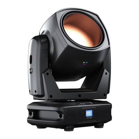
DTS Alchemy 7 User manual


RDM – DMX – Manual Ver. 1.01 1 di 47
ALCHEMY 7
Release 1.01
For more information
Language EN
Art-Net™ Designed by and Copyright Artistic Licence Holdings Ltd
All other trademarks, both marked and not marked, are the property of their respective owners.

RDM – DMX – Manual Ver. 1.01 2 di 47
ALCHEMY 7
ITA
Le informazioni contenute in questo documento sono state attentamente redatte e controllate. Tuttavia non è
assunta alcuna responsabilità per eventuali inesattezze. Tutti i diritti sono riservati e questo documento non può
essere copiato, fotocopiato, riprodotto per intero o in parte senza previo consenso scritto della D.T.S.
Illuminazione.
D.T.S. Illuminazione si riserva il diritto di apportare senza preavviso cambiamenti e modifiche estetiche funzionali
o di design a ciascun proprio prodotto. D.T.S. Illuminazione non assume alcuna responsabilità sull’uso o
sull’applicazione dei prodotti o dei circuiti descritti.
ENG
The information contained in this publication has been carefully prepared and checked. However, no
responsibility will be taken for any errors. All rights are reserved and this document cannot be copied,
photocopied or reproduced, in part or completely, without prior written consent from D.T.S. Illuminazione
D.T.S. Illuminazione reserves the right to make any aesthetic, functional or design modifications to any of its
products without prior notice. D.T.S. Illuminazione takes no responsibility for the use or application of the products
or circuits described herein.
FRA
Les informations contenues dans le présent manuel ont été rédigées et contrôlées avec le plus grand soin. Nous
déclinons toutefois toute responsabilité en cas d'éventuelles inexactitudes. Tous droits réservés. Ce document
ne peut être copié, photocopié ou reproduit, dans sa totalité ou partiellement, sans le consentement préalable
de D.T.S. Illuminazione.
D.T.S. Illuminazione. se réserve le droit d'apporter toutes modifications et améliorations esthétiques,
fonctionnelles ou de design, sans préavis, à chacun de ses produits. D.T.S. Illuminazione décline toute
responsabilité sur l'utilisation ou sur l'application des produits ou des circuits décrits.
ESP
Las informaciones contenidas en este documento han sido cuidadosamente redactadas y controladas. Con todo,
no se asume ninguna responsabilidad por eventuales inexactitudes. Todos los derechos han sido reservados y
este documento no puede ser copiado, fotocopiado o reproducido, total o parcialmente, sin previa autorización
escrita de D.T.S. Illuminazione.
D.T.S. Illuminazione se reserva el derecho a aportar sin previo aviso cambios y modificaciones de carácter
estético, funcional o de diseño a cada producto suyo. D.T.S. Illuminazione no se asume responsabilidad de
ningún tipo sobre la utilización o sobre la aplicación de los productos o de los circuitos descritos.
RDM – DMX – Manual Ver. 1.01 3 di 47
ALCHEMY 7
Table of Contents
1DMX Signal Connection ............................................................................................................................... 4
1.1 DMX Modes ......................................................................................................................................... 4
1.2 Setting Up the DMX Address ............................................................................................................... 5
2Art-Net / sACN Signal Connection ............................................................................................................... 5
2.1 Direct Ethernet Operation .................................................................................................................... 5
2.2 Ethernet to RDM/DMX Operation ........................................................................................................ 6
3RDM Functions............................................................................................................................................. 7
4Updating the Firmware............................................................................................................................... 10
5Rotating Framing System........................................................................................................................... 11
6Display Functions....................................................................................................................................... 12
7Error Messages.......................................................................................................................................... 19
8DMX Protocol ............................................................................................................................................. 21
8.1 DMX Personality 1 ............................................................................................................................. 21
8.2 DMX Personality 2............................................................................................................................ 26
8.3 DMX Personality 3............................................................................................................................ 31
8.4 DMX Personality 4............................................................................................................................ 36
8.5 DMX Personality 5............................................................................................................................ 41
8.6 All DMX Personality ......................................................................................................................... 46
NOTES ............................................................................................................................................................... 47

RDM – DMX – Manual Ver. 1.01 4 di 47
ALCHEMY 7
1 DMX Signal Connection
• The unit operates using the digital USITT DMX512 signal.
• Connection between the light controller and the projector, or between projectors, must be carried out using a
two-pair screened ø 0.5 mm cable, and a XLR 5 or 3 pins connector.
• Ensure that the conductors do not touch each other. Do not connect the ground cable to the XLR chassis.
The housing of the plug must be isolated.
• Connect the light controller to the DMX IN panel connector of the projector; to create a link to the next
projector, simply connect the DMX OUT plug of the former to the DMX IN plug of the new fixture in line.
Following this procedure, all the projectors will be cascade connected.
PS. If the display showing the DMX address flashes, then one of the following errors has occurred:
- DMX signal not present
- DMX reception problem
For installations where long distance DMX cable connections are needed, the use of a DMX terminator is
recommended.
The DMX terminator is a male XLR 3- or 5-pins connector with a 120 Ω resistor between pin 2 and pin 3.
The DMX terminator must be plugged in into the last unit’s DMX OUT panel connector of the DMX line.
Place a 120 Ω resistor between pin 2 and 3 of a male XRL
connector;
Plug the resistor into the DMX OUT panel connector of the last unit
connected to the DMX line.
1.1 DMX Modes
ALCHEMY 7 can be used in five different DMX modes:
•CCT (default mode);
•Advanced;
•Basic;
•Expo;
•CMY Emulation
e.g., when using the unit in “CCT” mode (20/25 DMX channels) (default), set the following addresses on the
light desk:

RDM – DMX – Manual Ver. 1.01 5 di 47
ALCHEMY 7
Projector 1 A001
Projector 2 A045 If you want to select the next projector, just add “44” to the former DMX address
Projector 3 A089
….. A….
projector 6 A221
1.2 Setting Up the DMX Address
1 Press the UP and DOWN key until you reach the desired DMX address. The numbers on the display will
start flashing (new DMX address hasn't yet been set).
2 Press ENTER to confirm your selection. The numbers on the display will stop flashing; the projector is now
set to the new DMX address.
TIP: if you keep pressed down the UP or DOWN keys, address scrolling will be quicker allowing thus for a
faster selection.
2 Art-Net / sACN Signal Connection
ALCHEMY 7 can be controlled through Art-Net / sACN signals.
Connection between the light controller and the projector must be carried out using a category 5 network cable
and a standard RJ45 connector.
2.1 Direct Ethernet Operation
For direct Ethernet operation, connect the light controller’s Art-Net / s-ACN output signal via Ethernet switch to
each unit’s etherCON RJ45 IN connector.
For each unit, scroll to “NETWORK” menu (refer to the paragraph “Display Function” for further details):
•Inside the “INPUT” menu, select “Art-Net” or “sACN” as input control signal.
•Inside the “IP ADDRESS MODE” menu, select “Default” or “Static” mode.
•Inside the “ETH TO DMX” menu, select ON.
•Set the IP address and Net Mask. IP address must be different for each unit on a network.
•Set the Art-Net or sACN Universe.

RDM – DMX – Manual Ver. 1.01 6 di 47
ALCHEMY 7
DMX address: 1 DMX address: 45 DMX address: 89
IP address: 002.214.192.007 IP address: 002.214.192.008 IP address: 002.214.192.009
Universe: 1 Universe: 1 Universe: 1
2.2 Ethernet to RDM/DMX Operation
For Ethernet to RDM/DMX operation, connect the light controller’s Art-Net / s-ACN output signal via Ethernet
switch to the etherCON RJ45 input connector of the first unit only.
In this configuration, the first unit works as an Ethernet-to-DMX converter and sends RDM/DMX signal to its
DMX output connector. All the other units must be connected as a DMX chain with standard DMX settings.
Only for the first unit, scroll until reaching “NETWORK” menu (refer to DISPLAY FUNCTIONS for details):
•Inside the “INPUT” menu, select “Art-Net” or “sACN” as input control signal.
•Inside the “IP ADDRESS MODE” menu, select “Default” or “Static” mode.
•Inside the “ETH TO DMX” menu, select ON.
•Set the IP address and Net Mask. IP address must be different for each unit on a network.
•Set the Art-Net or sACN Universe.
DMX address: 1 DMX address: 45 DMX address: 89
IP address: 002.214.192.007
Universe: 1
DMX address: 1 DMX address: 45 DMX address: 89
IP address: 002.214.192.008
Universe: 2
For installations where long-distance DMX cable connections are needed, the use of a DMX terminator is
recommended.
Please refer to page 4 for further information DMX terminators.

RDM – DMX – Manual Ver. 1.01 7 di 47
ALCHEMY 7
3 RDM Functions
By using a RDM controller, it is possible to read/set DMX addresses, DMX modes and other parameters.
ALCHEMY 7 accepts the following RDM commands:
RDM Device Model ID: - ALCHEMY 7: 0x001B
- ALCHEMY 7F: 0x001A
RDM PID DESCRIPTION RDM PID VALUE GET SET
Category – Network Management
DISC_UNIQUE_BRANCH 0x0001
DISC_MUTE 0x0002
DISC_UN_MUTE 0x0003
Category – Status Collection
STATUS_MESSAGES 0x0030 X
STATUS_ID_DESCRIPTION 0x0031 X
Category - RDM Information
SUPPORTED_PARAMETERS 0x0050 X
PARAMETERS_DESCRIPTION 0x0051 X
Category – Product Information
DEVICE_INFO 0x0060 X
DEVICE_MODEL_DESCRIPTION 0x0080 X
MANUFACTURER_LABEL 0x0081 X
DEVICE_LABEL 0x0082 X X
SOFTWARE_VERSION_LABEL 0x00C0 X
Category - DMX512 Setup
DMX_PERSONALITY 0x00E0 X X
DMX_PERSONALITY_DESCRIPTION 0x00E1 X
DMX_START_ADDRESS 0x00F0 X X
Category – Sensors
SENSOR_DEFINITION 0x0200 X
SENSOR_VALUE 0x0201 X X
Category – Power/Lamp Settings
DEVICE_HOURS 0x0400 X
LAMP_HOURS 0x0401 X
Category – Display Settings
DISPLAY_INVERT 0x0500 X X
Category – Configuration
PAN_INVERT 0x0600 X X
TILT_INVERT 0x0601 X X
Category – Control
IDENTIFY_DEVICE 0x1000 X X
Category – Dimmer Settings
CURVE 0x0343 X X
CURVE_DESCRIPTION 0x0344 X
OUTPUT_RESPONSE_TIME 0x0345 X X

RDM – DMX – Manual Ver. 1.01 8 di 47
ALCHEMY 7
RDM PID DESCRIPTION
RDM PID VALUE
GET
SET
OUTPUT_RESPONSE_TIME_DESCRIPTION 0x0346 X
MODULATION_FREQUENCY 0x0347 X X
MODULATION_FREQUENCY_DESCRIPTION 0x0348 X
Category – Custom PID
ETHERNET_TO_DMX 0x8000 X X
INPUT_PRIORITY 0x8001 X X
DISPLAY_STANDBY 0x8002 X X
FURTHER RDM MESSAGES:
CURVE
CURVE DESCRIPTION
1
LINEAR
2
QUADRATIC (default)
3
GAMMA 2.2
4
S-CURVE
OUTPUT RESPONSE TIME OUTPUT_RESPONSE_TIME_DESCRIPTION
1
SMOOTH OFF
2
SMOOTH 1 ( 25 ms)
3
SMOOTH 2 ( 50 ms)
4
SMOOTH 3 ( 75 ms)
5
SMOOTH 4 (100 ms) (default)
6
SMOOTH 5 (125 ms)
7
SMOOTH 6 (150 ms)
8
SMOOTH 7 (175 ms)
9
SMOOTH 8 (200 ms)
10
SMOOTH 9 (225 ms)
11
SMOOTH 10 (250 ms)
12
SMOOTH 11 (275 ms)
13 SMOOTH 12 (300 ms)
14
SMOOTH 13 (325 ms)
15
SMOOTH 14 (350 ms)
16
SMOOTH 15 (375 ms)
17
SMOOTH 16 (400 ms)
18
SMOOTH 17 (425 ms)
19
SMOOTH 18 (450 ms)
20
SMOOTH 19 (475 ms)
21
SMOOTH 20 (500 ms)

RDM – DMX – Manual Ver. 1.01 9 di 47
ALCHEMY 7
FURTHER RDM MESSAGES:
MODULATION FREQUENCY MODULATION FREQUENCY DESCRIPTION
1
610 Hz
2
800 Hz
3
1.000 Hz (default)
4
1.500 Hz
5
2.000 Hz
6 2.500 Hz
7
3.000 Hz
8
3.500 Hz
9
4.000 Hz
10
4.500 Hz
11
5.000 Hz
RDM MANUFACTURER’S SPECIFIC PIDs:
RDM CUSTOM PID DESCRIPTION
0x8000_ETHERNET_TO_DMX
Set parameter NETWORK – ETH TO DMX
0 = OFF (default)
1 = ON
0x8001_INPUT_PRIORITY
Set parameter NETWORK – PRIORITY
0 = DMX PORT (default)
1 = ETHERNET PORT
0x8002_DISPLAY_STANDBY
Set parameter DISPLAY – STANDBY
0 = DISABLED
1 = ENABLED (default)
2 = FORCED ENABLED
RDM STATUS MESSAGE IDs:
Status Message ID Data Value 1 Data Value 2 Status ID Description
0x8000
ERROR PAN MOTOR/ENCODER
0x8001
ERROR PAN LOCKED
0x8002
ERROR PAN ZERO SENSOR
0x8003
ERROR TILT MOTOR/ENCODER
0x8004
ERROR TILT LOCKED
0x8005
ERROR TILT ZERO SENSOR
0x8006
ERROR DMX ADDRESS
0x8007
ERROR PARAMETERS MEMORY
0x8008
ERROR SUPPLY VOLTS TOO LOW
0x8009
ERROR SUPPLY VOLTS TOO HIGH
0x800A
ERROR BUS ARTNET CARD
0x800B card number
ERROR BUS LED DRIVER CARD %d
0x800C card number
ERROR BUS MOTORS CARD %d
0x8013
ERROR ZOOM
0x801A
ERROR PROFILER INDEX (only ALCHEMY 7F)
0x801B
ERROR EFFECTS
0x801D prism number
ERROR PRISM %d INDEX
0x801F
ERROR TEMPERATURE LED MODULE
0x8020 sensor number
ERROR TEMPERATURE LED DRIVER %d

RDM – DMX – Manual Ver. 1.01 10 di 47
ALCHEMY 7
Status Message ID
Data Value 1
Data Value 2
Status ID Description
0x8021
ERROR TEMPERATURE MICRO
0x8027 sensor number
ERROR TEMPERATURE SENSOR %d
0x8028
1=data non present
ERROR COLOUR DATA INTEGRITY CODE %d
2=read error
3=incomplete data
4 Updating the Firmware
In order to update to the latest firmware release of ALCHEMY 7, you will need:
•DTS firmware uploader dongle (code 03.LA.206).
•“DTS Firmware Upgrade Utility v.2.02” program installed on PC (Windows OS).
•Latest firmware release available for the ALCHEMY 7 unit.
Updating to the latest firmware release:
To perform the update, please follow the procedure as described below:
1 Connect the DTS Firmware Uploader Dongle to a spare USB port on the PC.
2 Connect the unit’s DMX IN to the DTS Firmware Uploader Dongle’s DMX OUT with a standard DMX cable
and turn on the fixture.
3 Send the new firmware release into the unit by using “DTS Firmware Upgrade Utility v.2.02” program. At
the end of the procedure, the unit will commence a reset.
For more information, please refer to an authorized DTS service center.

RDM – DMX – Manual Ver. 1.01 11 di 47
ALCHEMY 7
5 Rotating Framing System
PAN DMX value = 128
TILT DMX value = 224
PAN DMX value = 128
TILT DMX value = 224
PAN DMX value = 128
TILT DMX value = 224
255
DMX
value
128
DMX
value
128
DMX
value
128
DMX
value
0
DMX
value
-100° Full system rotation +100° Full system rotation
0° Full system rotation

RDM – DMX – Manual Ver. 1.01 12 di 47
ALCHEMY 7
6 Display Functions
The ALCHEMY 7 display panel shows all the available control menus.
By selecting the available functions on these menus, you will be able to change the fixture’s settings and
behavior.
Beware that changing these settings may vary the operating functions of the unit so that it may not respond
correctly to the signal given to it. Carefully read the instructions and tables below before carrying out any
variations or selections.
MENU
•To access the control menus in the display panel.
•To return to the previous level in the menu structure without making a
change.
•To exit the menus.
ENTER
•To select any required menu.
•To confirm any changes.
UP / DOWN
•To navigate the menus structure.
•To change or scroll between any values.
Motors Firmware Release
LED Firmware Release
10
1.00
RDM Device Model ID
ALCHEMY 7: 0x001B
ALCHEMY 7F: 0x001A
DMX Personality IDs
0x01 “CCT”
0x02 “ADVANCED”
0x03 “BASIC”
0x04 “EXPO”
0x05 “CMY EMULATION”

RDM – DMX – Manual Ver. 1.01 13 di 47
ALCHEMY 7
“Display Key-Lock” Function
This function can be enabled/disabled by contemporary pressing ENTER + DOWN keys for 3 seconds.
“Zero Skip” Function
“Zero skip” function can be activated by contemporary pressing MENU + UP during initial reset.
This function allows to have the display active while all motors are turned off. This can be useful when the unit,
while still being inside the flightcase, needs to be DMX-addressed or when its other parameters need to be set.
MAIN MENU
LEVEL 1
LEVEL 2
LEVEL 3
FUNCTION
NETWORK
INPUT
DISABLED
Allows to disable Ethernet
operation (Default).
ARTNET
Allows to select Art-Net as input
control signal protocol.
SACN
Allows to select sACN as input
control signal protocol.
IP ADDR MODE
DEFAULT
Allows to select the mode to set
the IP address and the Net
Mask.
Fixed IP address with manual
setting of first byte only and
fixed Net Mask (Default).
STATIC
Manual setting of IP address
and Net Mask.
DEFAULT IP IP 2.214.192. 7
MASK 255. 0. 0. 0
Fixed IP address and Net
Mask. It is possible to set only
first byte of the IP address.
IP address must be different
for each unit on a network.
ARTNET UNIV. 00000 - 32767
Allows to set the Art-Net
Universe (range 0÷32767).
SACN
UNIVERSE
00001 - 63999
Allows to set the sACN
Universe (range 1÷63999).
PRIORITY DMX512
Allows to set the priority
between input control signals
when the unit is connected via
DMX and via ETHERNET at the
same time.
RDM / DMX signal has the
priority on the Art-Net / sACN
signal (Default).

RDM – DMX – Manual Ver. 1.01 14 di 47
ALCHEMY 7
MAIN MENU
LEVEL 1
LEVEL 2
LEVEL 3
FUNCTION
ETHERNET
Art-Net / sACN signal has the
priority on the DMX signal.
ETH TO DMX
OFF
Allows to enable ETHERNET to
RDM/DMX operation.
Default = OFF.
ON
In this configuration the first unit
works as an Ethernet to DMX
converter and sends RDM/DMX
signal to its DMX output
connector.
NO SIGNAL KEEP LAST
Allows to set the desired
unit’s behavior in case Art-Net
or sACN signal is missing or not
available.
Keep last valid Art-Net or
sACN signal (Default).
BLACKOUT
Black-out.
PAN
DIRECTION
NORMAL
Allows to set the Pan
movement.
Normal or Reverse.
Default = Normal
REVERSE
TILT
DIRECTION
NORMAL
Allows to set the Tilt movement.
Normal or Reverse.
Default = Normal
REVERSE
ZOOM
DIRECTION
NORMAL
Allows to set the Zoom
movement.
Normal or Reverse.
Default = Normal
REVERSE
OPERATING
MODE
SILENT
Reduced Pan-Tilt-Zoom-Fans
speed for low noise operation
(Default).
ULTRASILENT
Reduced Pan-Tilt-Zoom-Fans
speed for ultra low noise
operation.
STANDARD
Pan-Tilt-Zoom-Fans standard
speed.
FAN MODE
(FAN MODE will
work relatively
to OPERATING
MODE)
CONSTANT
Same fans speed in any
working condition in SILENT,
ULTRASILENT and
STANDARD operating mode
(Default).
AUTOMATIC
Automatic fans speed.
If LED temperature <40°C: fans
OFF.
If LED temperature >40°C:
If OPERATING MODE =
SILENT, fans speed is
increased within the values
range set in SILENT mode;
If OPERATING MODE =
ULTRASILENT, fans speed is
increased within values range
set in ULTRASILENT mode;
If OPERATING MODE =
STANDARD, fans speed is
increased within values range
set in STANDARD mode.
DISPLAY
FLIP
AUTO
Reverses display’s reading
depending on the mounting
position. Automatic, on the
ground or suspended.
Automatic (Default).
ON THE GROUND
SUSPENDED
STANDBY
DISABLED
Display stand-by disabled
(Default).
ENABLED
Display goes OFF after 5
seconds.

RDM – DMX – Manual Ver. 1.01 15 di 47
ALCHEMY 7
MAIN MENU
LEVEL 1
LEVEL 2
LEVEL 3
FUNCTION
FORCED ENABLED
Display forced OFF even if
control signal is missing or error
messages are shown.
CONTRAST 20 - 35
Display contrast regulation.
Range 20-35. Default = 25.
DMX MODE
Personality
CCT
Allows to select CCT mode
(20/25 DMX channels).
Default.
-ALCHEMY 7: 20 channels;
-ALCHEMY 7F:25 channels.
ADVANCED
Allows to select ADVANCED
mode (28/32 DMX channels).
-ALCHEMY 7: 28 channels;
-ALCHEMY 7F:32 channels.
BASIC
Allows to select BASIC mode
(23/27 DMX channels).
-ALCHEMY 7: 23 channels;
-ALCHEMY 7F:27 channels.
EXPO
Allows to select EXPO mode
(13/19 DMX channels).
-ALCHEMY 7: 13 channels;
-ALCHEMY 7F:19 channels.
CMY
EMULATION
Allows to select CMY
EMULATION mode (23/27
DMX channels).
-ALCHEMY 7: 23 channels;
-ALCHEMY 7F:27 channels.
NO DMX
ACTION
KEEP LAST
DMX
Allows to set the desired unit’s
behavior in case DMX signal is
missing or not available.
Keep last valid DMX signal
(Default).
PROGRAM
1 - 48 1 - 48
48 pre-programmed steps.
Speed time values (range 0.5x -
3x) selectable by user (default
1x).
SINGLE CUE
PAN MSB 0 - 255
Fixed cue with values
selectable by user.
Default = 128
PAN LSB
0 - 255
Default = 128
TILT MSB
0 - 255
Default = 128
TILT LSB
0 - 255
Default = 128
SPEED MOVEMENT
0 - 255
Default = 0
SHUTTER
0 - 255
Default = 15
DIMMER MSB
0 - 255
Default = 255
DIMMER LSB
0 - 255
Default = 255
CCT
0 - 255
Default = 0
GEL LIBRARY
0 - 255
Default = 0
RED
0 - 255
Default = 255
GREEN
0 - 255
Default = 255
BLUE
0 - 255
Default = 255
AMBER
0 - 255
Default = 255
CYAN
0 - 255
Default = 255
LIME
0 - 255
Default = 255
EFFECT WHEEL
0 - 255
Default = 0
BEAM SHP R - I
0 - 255
Default = 0
BLADE SYS ROT.
(only
ALCHEMY 7F)
0 - 255 Default = 128
BLADE 1 INS.
(only ALCHEMY 7F)
0 - 255 Default = 0
BLADE 1 ROT.
(only ALCHEMY 7F)
0 - 255 Default = 128

RDM – DMX – Manual Ver. 1.01 16 di 47
ALCHEMY 7
MAIN MENU
LEVEL 1
LEVEL 2
LEVEL 3
FUNCTION
BLADE 2 INS.
(only ALCHEMY 7F) 0 - 255 Default = 0
BLADE 2 ROT.
(only ALCHEMY 7F)
0 - 255 Default = 128
ZOOM
0 - 255
Default = 128
RESTORE DEF.
To restore parameters default
settings.
BLACKOUT
Black-out.
RESET
BY DMX
ENABLED
Reset via DMX enabled
(Default).
DISABLED
Reset via DMX disabled.
NOW
Instant unit motors reset.
LED
SMOOTH OFF - 20
Allows to select the value of
delay (in ms) for DIMMER
channel reaction to DMX
dimming command.
OFF = Instant response.
4 = 100 ms smooth response
(Default).
20 = 500 ms smooth response.
GAMMA CORR.
QUAD
Allows to set quadratic
current output for LED
(Default).
2.2
Allows to set gamma curve 2.2
.
S-CURVE
Allows to set S-curve to
emulates light intensity
characteristics of the tungsten
halogen lamps.
LINE
Allows to set linear light output.
FREQUENCY 610 - 5000 HZ
Allows to adjust the PWM
frequency value (Hz) in order to
reduce flickering in the process
of camera recordings.
Range = 610 Hz - 5 KHz
Default = 1000 Hz
TUNGSTEN
EMU.
DISABLED
Allows to enable Tungsten
Emulation. Variation in the
dimmer intensity will affect CCT
values.
Disabled (Default).
ENABLED
TRANSITION
INTERMEDIATE
Allows to set Crossfade
Intermediate for ‘GELS X-
FADE’ channel 12 of
“ADVANCED” DMX mode
(Default).
TRANSITION
Allows to set Crossfade
Transition for ‘GELS X-FADE’
channel 12 of “ADVANCED”
DMX mode.
“GAMMA CORR.” graphics:

RDM – DMX – Manual Ver. 1.01 17 di 47
ALCHEMY 7
“CROSSFADE” graphics:
MAIN MENU
LEVEL 1
LEVEL 2
LEVEL 3
FUNCTION
SYSTEM INFO
SOFTWARE
ALCHEMY 7 / 7F
10 SEP 2019
MOTOR: V.1.0
LED: V.1.0
Unit model, motors firmware
release date, Motors board
and LED Driver board
firmware release.
TEMP. 1
LED: 041°C
DRV-1: 043°C
DRV-2: 044°C
MICRO: 040°C
DRV-1: 043°C
DRV-2: 044°C
MICRO: 040°C
LED: LED temperature
monitoring.
DRV-1: output 1/4 of Master
LED Driver board temperature
monitoring.
DRV-2: output 5/8 of Master
LED Driver board temperature
monitoring.
DRV-1: output 1/4 of Slave
LED Driver board temperature
monitoring.
DRV-2: output 5/8 of Slave
LED Driver board temperature
monitoring.
MICRO: Micro controller
temperature monitoring.
TEMP. 2
5M-1: 025°C
5M-2: 024°C
5M-3: 026°C (only
ALCHEMY 7F)
Temperatures detected by
5Motors-1 / 2 / 3.*
TIME COUNTERS
UNIT: 0082H
DRIVER: 0080H
RED: 0045H
GREEN: 0068H
BLUE: 0023H
AMBER: 0037H
CYAN: 0067H
LIME: 0058H
Unit, LED Driver board and
LED channels life time.*
ADDRESSES
RDM:
0710:0001196B
MAC:
70:B3:D5:D7:C7:DF
RDM and MAC Ids.
RESERVED
ENTER CODE
0 - 255
(code 100)
PAN LOCK NO
Lock the Pan to the desired
value.
Default = NO
YES
TILT LOCK
NO
Lock the Tilt to the desired
value.
Default = NO
YES
PAN FREE
NO
Remove power to Pan motor.
Default = NO
YES
TILT FREE
NO
.Remove power to Tilt motor.
Default = NO
YES
LOCK DETECTOR
ON
Allows to activate the Lock
detector on Pan and Tilt.
If for any reason there is
something blocking the
movement for Pan&Tilt motors
during the initial reset
(example unit into the flight
OFF

RDM – DMX – Manual Ver. 1.01 18 di 47
ALCHEMY 7
MAIN MENU
LEVEL 1
LEVEL 2
LEVEL 3
FUNCTION
case and power connected), it
automatically will stop to reset
Pan&Tilt motors after 5
seconds from the startup and
a warning message (Pan
locked-Tilt-locked) will appear
on unit display.
Default = ON.
REBOOT
Unit reboot without needing of
turning OFF the unit.
EXIT TO MAIN
Exit from Reserved menu.
DEFAULT
To restore factory settings.
MANUAL
CONTR.
RESET
HEAD MOTORS
To reset head motors only.
PAN TILT
To reset Pan and Tilt only.
ALL MOTORS
To reset all motors.
RESTORE DEF.
To restore parameters default
settings.
PAN MSB 0 - 255
Manual mode with functions
value selectable by user.
Default = 128
PAN LSB
0 - 255
Default = 128
TILT MSB
0 - 255
Default = 128
TILT LSB
0 - 255
Default = 128
SPEED MOV.
0 - 255
Default = 0
DIMMER MSB
0 - 255
Default = 15
DIMMER LSB
0 - 255
Default = 255
SHUTTER
0 - 255
Default =255
CCT
0 - 255
Default = 0
GEL LIBRARY
0 - 255
Default = 0
RED
0 - 255
Default = 255
GREEN
0 - 255
Default = 255
BLUE
0 - 255
Default = 255
AMBER
0 - 255
Default = 255
CYAN
0 - 255
Default = 255
LIME
0 - 255
Default = 255
EFFECTS WHEEL
0 - 255
Default = 0
BEAM SHP R-I
0 - 255
Default = 0
BLADE SYS.
ROT.
(only ALCHEMY 7F)
0 - 255 Default = 128
BLADE 1 INS.
(only ALCHEMY 7F)
0 - 255 Default = 0
BLADE 1 ROT.
(only ALCHEMY 7F)
0 - 255 Default = 128
BLADE 2 INS.
(only ALCHEMY 7F)
0 - 255 Default = 0
BLADE 2 ROT.
(only ALCHEMY 7F)
0 - 255 Default = 128
ZOOM
0 - 255
Default = 128
* Refer to User Manual for Motors and LED Driver PCBs details.
Other manuals for Alchemy 7
1
Table of contents
Other DTS Lighting Equipment manuals

DTS
DTS DELTA 12 HEAD User manual

DTS
DTS SCENA COMPACT LED 50 User manual

DTS
DTS NicKWash 600 User manual

DTS
DTS DELTA R FULL COLOR User manual

DTS
DTS MOON 575 User manual

DTS
DTS Delta 8 White + Amber R User manual

DTS
DTS A.R.C. User manual

DTS
DTS NICK NRG1200 CT User manual

DTS
DTS Thomas & Betts NT 06 Manual

DTS
DTS SCENA COMPACT LED 50 User manual