2
Instruction Leaflet IL29C149B
Effective December 2011
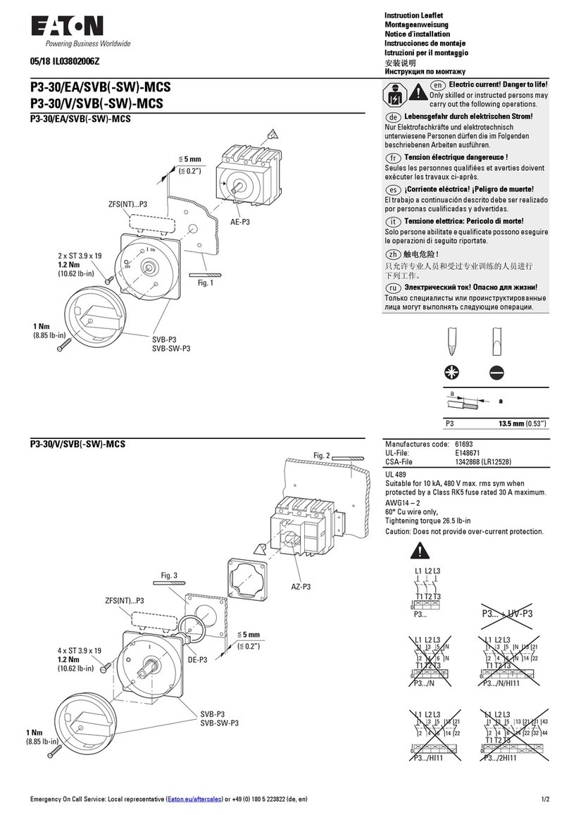
Installation Instructions for Low Energy ShuntTrip for NDB, ND,
NDC, HND, NW, HNW, NWC Circuit Breakers, Series C Molded
Case Switches, and Motor Circuit Protectors (HMCP)
EATON CORPORATION www.eaton.com
CONTACT WITH ENERGIZED EQUIPMENT CAN
RESULTIN DEATH, SEVERE PERSONAL INJURY,
OR SUBSTANTIAL PROPERTY DAMAGE. DO NOT
ATTEMPT TO INSTALL OR PERFORM MAINTE
-
NANCE ON EQUIPMENT WHILE IT IS ENERGIZED.
ALWAYS VERIFY THATNO VOLTAGE IS PRESENT
BEFOREPROCEEDING WITH THE TASK, AND
ALWAYS FOLLOW GENERALLY ACCEPTED SAFE
-
TY PROCEDURES.
THEEATON CORPORATION IS NOTLIABLE
FOR THEMISAPPLICATION OR MISINSTAL-
LATION OF ITS PRODUCTS.
The user is cautioned to observe all recommendations,
warningsandcautions relating to the safety of person
-
nel and equipment well as as general andlocal health
andsafety laws, codes andprocedures.
The recommendationsandinformation contained herein
are based on Eaton experience andjudgment, but
should not be considered to be all
-
inclusive or covering
everyapplication or circumstance which mayarise. If
anyquestions arise, contact Eaton for further inform-
ation or instructions.
1
-
0
INTRODUCTION
General Information
The low energy shunt trip (LEST) is designed to inter
-
face with a customerground fault detection system
(Figure 1-1). The LEST consists of an intermittent
rated solenoid with a plunger and a reset leverassem
-
bled to a plug
-
in module. The plug
-
in module is mount
-
ed in slots in the top of the trip unit andoccupies the
accessory cavity in the circuit breaker frame. The reset
lever resets the LEST when the trip signal is removed
and the circuit breaker handle is moved to the reset
(extreme OFF) position.
The LEST is designed to trip the circuit breaker when a
100
microfarad capacitor charged to 28 Vdc is dis
-
charged through the solenoid.
For this publication, the termcircuit breaker shall also
include molded caseswitch andmotor circuit protector.
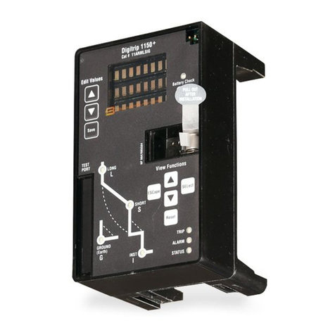
Figure 1 1
-
Low
EnergyShunt Trip Installed in N
-
Frame
Circuit Breaker.
Depending on the model ordered, connections for the
LEST are in one of four forms. The standard wiring con
-
figuration is pigtail leads exiting the rear of the base
directly behind the LEST. Optionalconfigurations
include a terminal block mounted on the sameside of
the baseas the accessory, leads exiting the side of the
base where the accessory is mounted,andleads exiting
rear of the base on the side opposite the accessory.
The 18
-
inch (457.2 mm) long pigtail leads arecolorcoded
for identification; identification labels areprovided for pig-
tail leadsand terminal block points. For allowable locat-
ions of all accessories, refer to Frame Book 29
-
1
04.
When the walking beam interlock is used with the
circuit breaker, the rear trough cannot be used for
accessory pigtail leads.
Thisinstruction leaflet (IL) gives detailed procedures for
installing the LEST.

