manuals.online logo
Brands
  1. Home
  2. •
  3. Brands
  4. •
  5. Eaton
  6. •
  7. Circuit Breaker
  8. •
  9. Eaton 4000A MiniMod User manual

Eaton 4000A MiniMod User manual

66A5400H01
1
Instruction Booklet for the Installation, Operation and Maintenance
of Type 5-15 kV VCP-WG Vacuum Circuit Breaker 4000A MiniMod
Eaton Corporation
Moon Twp, PA. U.S.A. 15108
66A5400H01
2
INTRODUCTION
READ AND UNDERSTAND THESE INSTRUCTIONS BEFORE ATTEMPTING TO
USE THIS DEVICE. IMPROPER USE CAN RESULT IN DEATH, BODILY INJURY
AND/OR PROPERTY DAMAGE.
SAFETY PRECAUTIONS:
All safety codes, safety standards and/or regulations must be strictly observed in the installation, operation and
maintenance of this device.
WARNING
THE WARNINGS AND CAUTIONS INCLUDED AS PART OF THE PROCEDURAL STEPS IN THIS DOCUMENT ARE
FOR PERSONNEL SAFETY AND PROTECTION OF EQUIPMENT FROM DAMAGE. AN EXAMPLE OF A TYPICAL
WARNING LABEL HEAD-
ING IS SHOWN ABOVE IN REVERSE TYPE TO FAMILIARIZE PERSONNEL WITH THE STYLE OF
PRESENTATION. THIS WILL HELP TO INSURETHAT PERSONNEL ARE ALERT TO WARNINGS, WHICH MAY
APPEAR THROUGHOUT THE DOCUMENT. IN ADDITION, CAUTIONS ARE ALL UPPER CASE AND BOLDFACE
AS SHOWN BELOW.
CAUTION
COMPLETELY READ AND UNDERSTAND THE MATERIAL PRESENTED IN THIS DOCUMENT BEFORE
ATTEMPTING INSTALLATION, OPERATION OR APPLICATION OF THE EQUIPMENT. IN ADDITION, ONLY
QUALIFIED PERSONS SHOULD BE PERMIT-TED TO PERFORM ANY WORK ASSOCIATED WITH THE EQUIPMENT.
ANY WIRING INSTRUCTIONS PRESENTED IN THIS DOCUMENT MUST BE FOLLOWED PRECISELY. FAILURE TO
DO SO COULD CAUSE PERMANENT EQUIPMENT DAMAGE.
WARNING
SATISFACTORY PERFORMANCE OF THESE MINIMOD AND OR BREAKERS IS CONTINGENT UPON PROPER
APPLICATION, CORRECT INSTALLATION AND ADEQUATE MAINTENANCE. THIS INSTRUCTION BOOK MUST BE
CAREFULLY READ AND FOLLOWED IN ORDER TO OBTAIN OPTIMUM PERFORMANCE FOR LONG USEFUL LIFE
OF THE MINIMOD AND OR CIRCUIT BREAKER ELEMENTS.
66A5400H01
3
DESCRIPTION
The Eaton 4000A Mini-Mod is an integrated assembly for drawout vacuum circuit breakers, bus
and control devices coordinated electrically and mechanically for medium voltage circuit protection
and control. The metal-clad integrity provides maximum circuit separation and safety.
All circuit breakers are equipped with self-aligning and self-coupling primary and secondary
disconnecting devices, and arranged with a mechanism for moving it physically between connected
and disconnected positions.
All major primary components, such as circuit breaker, voltage transformer, control power
transformer and buses are completely enclosed and grounded by metal barriers.
A metal barrier in front of the circuit breaker and auxiliary drawer ensures that, when in the
connected position, no live parts are exposed by opening the compartment door.
Automatic shutters cover primary circuit elements when the removable element is in the
disconnected, test or removed position.
All primary bus conductors and connections are insulated with track-resistant fluidized bed epoxy
coating for rated maximum voltage of the assembly.
Mechanical interlocks are provided to maintain a proper and safe operating sequence.
Instruments, meters, relays, secondary control devices and their wiring are isolated, where
necessary, by grounded metal barriers from all primary circuit elements.
Corona emissions within the Mini-mod assemblies have been eliminated or reduced to very low
levels by special fabrication and assembly techniques.
By making switchgear assemblies corona free, Eaton Corporation has made its switchgear more
reliable.
Circuit Breaker Compartment
The mechanism for levering the breaker is a unique cell mounted design. It incorporates all the
safety interlocks to render the breaker mechanically and electrically trip free during the levering
procedure.
A silver plated copper ground bus provided on the levering pan assembly is engaged by a spring
loaded ground contact on the circuit breaker to ensure that the circuit breaker remains grounded
throughout its travel.
66A5400H01
4
Figure #1: View of the 4000A MiniMod with part descriptions.
66A5400H01
5
Figure #2: Outline drawing with reference dimensions.
66A5400H01
6
Figure #3 and #4: View of the breaker in the text and connected positions.
66A5400H01
7
Figure #5: View of the breaker on the rails getting ready to be racked in the MiniMod.
Figure #6: View of the breaker racked in the MiniMod.
66A5400H01
8
Figure #7: View inside the MiniMod.
66A5400H01
9
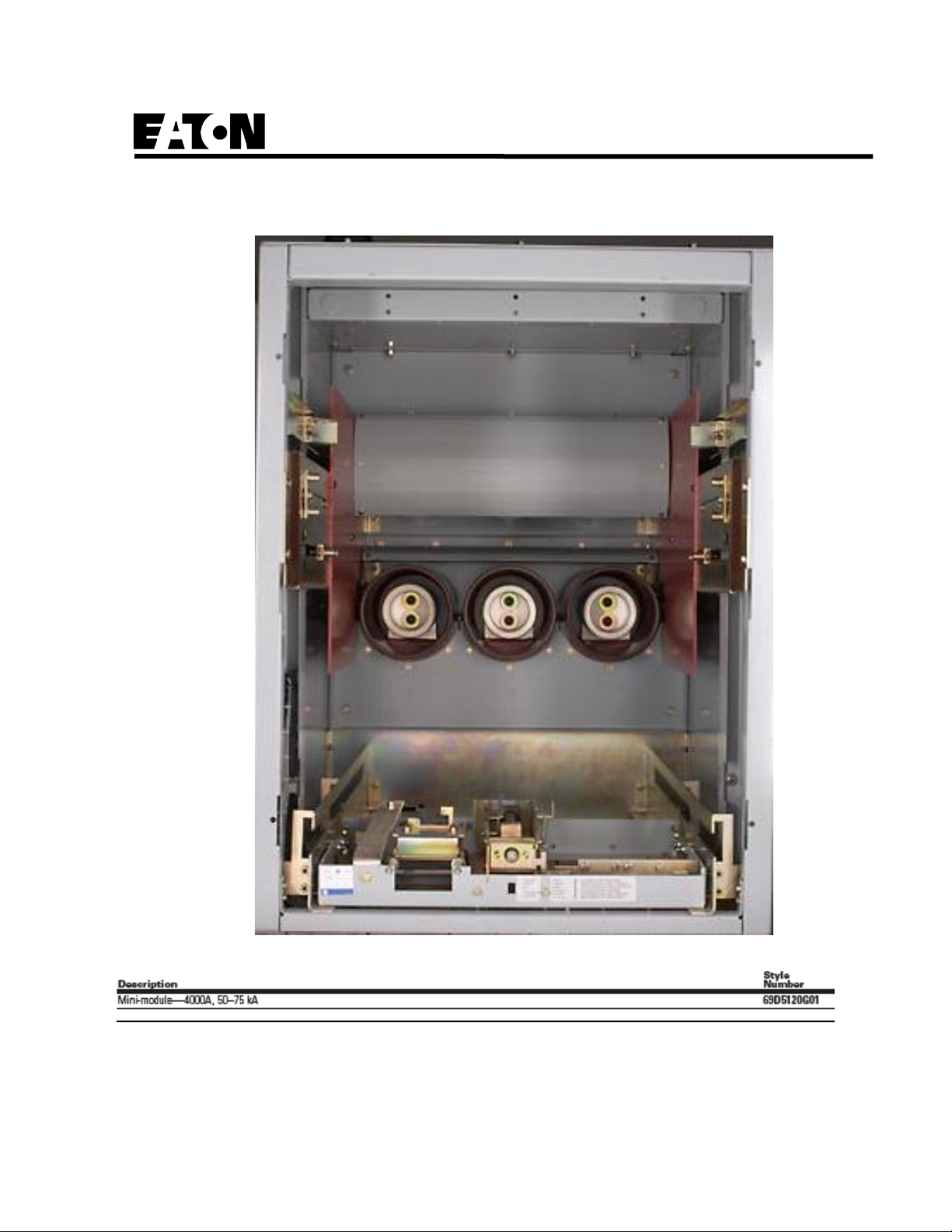
MiniMod Un-Packing and Incoming Inspection:
If the MiniMod is to be placed in storage, maximum protection can be obtained by keeping it packed as
shipped. Before placing it in storage, checks should be made to make sure that the unit is free from shipping
damage and is in satisfactory operating condition.
The MiniMod is shipped within a wood crate. When it arrives and needs to be unpacked then the
top of the crate should be removed first. Then the sides should be removed. The unit should be
kept on the bottom pallet temporarily. Inspect the unit for shipping damage and or missing parts.
Make sure the red brick colored spouts in the back of the units do not have any significant cracks.
If any problems are found then please contact your local Eaton Salesman or EESS for repair /
replacement parts. The unit can now be moved around via a pallet jack and or fork lift truck.
Eaton suggests moving the unit around attached to the pallet. This is due to the large size of the
unit and the unbalanced weight of the unit. Eaton suggests the wood crate be saved in storage as
long as possible in case it is needed. The MiniMod is supplied with lifting hooks and or lifting
metal strips located on the top of the unit. A large overhead crane can be used to life the unit.
These lifting hooks or lifting metal straps can be removed during the installation process.
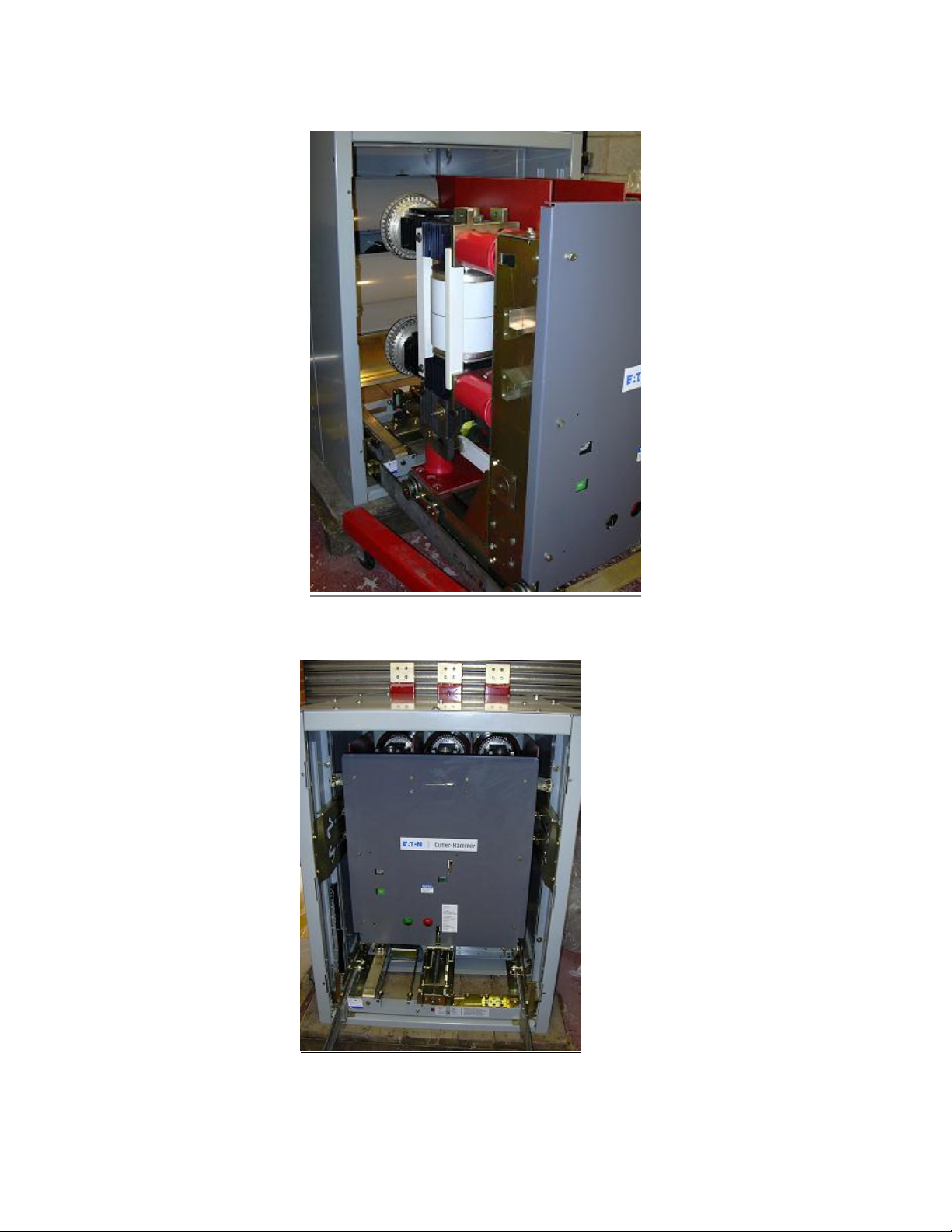
MiniMod Operational Inspection:
It is best to perform this testing with the MiniMod on the pallet outside of the switchgear. We do not
suggest you mount the MiniMod in the switchgear and then perform these tests. Testing with just the
breaker and MiniMod allows for the user to see the operation from all sides and avoid any damage to the
breaker and or MiniMod.
Test the operation of the left hand and right hand shutter drivers by pushing them by hand forward and
backwards. If binding is found then try to remove the foreign item causing the binding. If required grease
the parts to improve the operation.
Frequency of Inspection and Maintenance:
Periodic inspections and associated maintenance are essential to the safe and reliable operation of the
MiniMod and VCP-WG Vacuum Circuit Breaker Elements. The inspection frequency and associated
maintenance recommended are intended to insure the best possible ongoing service. It is imperative that an
established schedule be followed. To establish an exact schedule for a specific installation, use the following
guidelines:
1. Customers such as Utilities having extensive experience with Power Distribution components should
schedule their inspection and maintenance intervals using well established best practices in their industry.
2. All other customers should use the following guidelines as good conservative practice:
a. In a clean, non-corrosive environment, inspect and maintain each MiniMod annually or after
every 100 levering in operations, whichever comes first.
66A5400H01
10
b. For special conditions such as frequent levering in operations, contaminated environments, and
high temperature/humidity conditions, the inspection frequency should be a minimum of twice
per year.
3. Fault interruptions have the greatest impact on the MiniMod. MiniMod that have been subjected to 15
full rated fault interruptions should be immediately inspected and the schedule for inspection and
maintenance should be re-evaluated based upon the inspection results. Additionally, because of the
variability of system fault characteristics, if there are any customer uncertainties in the records of the
magnitude, duration, or other fault details, increased inspection frequency should be considered.
4. The unit should be visually examined to make sure there is no cracking of the insulation parts and
damage done to the internal components.
5. Create and maintain a dated permanent record of all inspections, maintenance performed, actions taken,
observations made, and measurements taken. Not only will this provide valuable historical information, it
can help to establish whether or not the present schedule needs to be adjusted.
6. Perform ongoing visual inspections, when possible, of all equipment on a regular basis. Be alert for an
accumulation of dirt in and around the primary contacts, loose hardware and or discolored insulation.
For assistance in establishing or updating a detailed Inspection and Maintenance schedule for a specific
application, please contact your local Eaton representative.
General Torque Guidelines:
Bolts and screws must be properly torqued. This is especially true if part and/or accessories are added or
replaced. The table below provides guidelines on torque levels. The table is intended as a general guideline
and should be applied in conjunction with the experience and good judgment of the individual performing
the work.
Bolt Size
Torque (LB-IN)
8 - 32
24
10 - 32
36
1/4 - 20
72
5/16 - 18
144 (12 lb-ft)
3/8 - 16
300 (25 lb-ft)
1/2 - 13
540 (45 lb-ft)
66A5400H01
11
Troubleshooting:
a) Insulation: Visually inspect the insulators, barriers, spouts, boots,… for dirt, dust, and cracking. If
problems are identified then clean and or replace the components are required.
b) Corona: Visually inspect the insulators, barriers, spouts, boots,… for signs of corona discharge.
This can normally be identified by holes in the insulation, white powder like substance on the
insulation, burn marks,… If problems are identified then clean and or replace the components are
required. Adjust the design to improve the corona performance by contacting your local Eaton
Salesman and or use switchgear common best practices.
c) Insulation Integrity: Insulation integrity should be checked on a yearly basis via performing a
standard industry HiPot test via a HiPot test machine.
d) Control Circuit Wiring: Visually inspect all secondary control voltage wiring. Make sure the
components work correctly and operate smoothly. Replace any worn or defective wiring.
e) Shutter operating mechanism: Visually inspect the proper operation of the shutter drivers. If
binding is found then remove the foreign elements causing the binding. If parts are found bent or
damaged then replace the damaged parts. If required grease the moving components.
f) Levering In operating mechanism: Visually inspect the proper operation of the levering in system.
If binding is found then remove the foreign elements causing the binding. If parts are found bent or
damaged then replace the damaged parts. If required grease the moving components.
Quality Test:
In order to perform a quality test of the MiniMod a standard 31” frame VCP-WG breaker should be racked in
and out of the MiniMod. Perform this test five times. After the end of the fifth operation the testing is
complete. The unit can then be mounted into the switchgear.
Check to make sure the breaker can successfully be racked in and out of the MiniMod without any of the
components binding, rubbing, and or breaking. If problems are identified then contact your local Eaton
Salesman or EESS for repair / replacement parts.
66A5400H01
12
This instruction booklet is published solely for information purposes and should not be considered all inclusive. If
further information is required, you should consult Eaton.
Sale of product shown in this literature is subject to terms and conditions outlined in appropriate Eaton selling
policies or other contractual agreement between the parties. This literature is not intended to and does not enlarge or
add to any such contract. The sole source governing the rights and remedies of any purchaser of this equipment is
the contract between the purchaser and Eaton.
NO WARRANTIES, EXPRESSED OR IMPLIED, INCLUDING WARRANTIES OF FITNESS FOR A PARTICULAR
PURPOSE OR MERCHANTABILITY, OR WARRANTIES ARISING FROM COURSE OF DEALING OR USAGE OF
TRADE, ARE MADE REGARDING THE INFORMATION, RECOMMENDATIONS AND DESCRIPTIONS
CONTAINED HEREIN. In no event will Eaton be responsible to the purchaser or user in contract, in tort (including
negligence), strict liability or otherwise for any special, indirect, incidental or consequential damage or loss
whatsoever, including but not limited to damage or loss of use of equipment, plant or power system, cost of capital,
loss of power, addition-al expenses in the use of existing power facilities, or claims against the purchaser or user by
its customers resulting from the use of the information, recommendations and description contained herein.

This manual suits for next models

1

Other Eaton Circuit Breaker manuals

Eaton ZB-XPLH Manual

Eaton

Eaton ZB-XPLH Manual

Eaton P1 /I2 Series Manual

Eaton

Eaton P1 /I2 Series Manual

Eaton QSA63N1 Series Manual

Eaton

Eaton QSA63N1 Series Manual

Eaton D6 WMZS2D06 User manual

Eaton

Eaton D6 WMZS2D06 User manual

Eaton NZMB Series Manual

Eaton

Eaton NZMB Series Manual

Eaton CPKZ0 Series Manual

Eaton

Eaton CPKZ0 Series Manual

Eaton xComfort CSEZ-01/17 User manual

Eaton

Eaton xComfort CSEZ-01/17 User manual

Eaton L-PKZ0 Series Manual

Eaton

Eaton L-PKZ0 Series Manual

Eaton VCPW-HD SMG User manual

Eaton

Eaton VCPW-HD SMG User manual

Eaton Z-ASA Guide

Eaton

Eaton Z-ASA Guide

Eaton Power Defense PD3 Operating and safety instructions

Eaton

Eaton Power Defense PD3 Operating and safety instructions

Eaton NZM2-XKAM-NA Manual

Eaton

Eaton NZM2-XKAM-NA Manual

Eaton XTPE(A)036BCSNLSOND533 Series Manual

Eaton

Eaton XTPE(A)036BCSNLSOND533 Series Manual

Eaton NZM1-4-XFI300R Manual

Eaton

Eaton NZM1-4-XFI300R Manual

Eaton LN3 Series Manual

Eaton

Eaton LN3 Series Manual

Eaton IKA-SOL20 Series Manual

Eaton

Eaton IKA-SOL20 Series Manual

Eaton NZM2-XKR Manual

Eaton

Eaton NZM2-XKR Manual

Eaton Series NRX Manual

Eaton

Eaton Series NRX Manual

Eaton CH 3/4" Series Manual

Eaton

Eaton CH 3/4" Series Manual

Eaton Power Defense PDG5 Manual

Eaton

Eaton Power Defense PDG5 Manual

Eaton Cutler Hammer C30CN Series User manual

Eaton

Eaton Cutler Hammer C30CN Series User manual

Eaton DILMS17 Series Manual

Eaton

Eaton DILMS17 Series Manual

Eaton Power Defense IZMX40 Manual

Eaton

Eaton Power Defense IZMX40 Manual

Eaton Power Defense PDC9-ETU User manual

Eaton

Eaton Power Defense PDC9-ETU User manual

Popular Circuit Breaker manuals by other brands

NHP TERASAKI TEMBREAK PRO operating instructions

NHP

NHP TERASAKI TEMBREAK PRO operating instructions

OEZ LTS Instructions for use

OEZ

OEZ LTS Instructions for use

Siemens 3ZX1012-0RV01-1AA1 operating instructions

Siemens

Siemens 3ZX1012-0RV01-1AA1 operating instructions

Siemens SIRIUS 3RV2 3 Series Original operating instructions

Siemens

Siemens SIRIUS 3RV2 3 Series Original operating instructions

Circutor RECmax-CVM series instruction manual

Circutor

Circutor RECmax-CVM series instruction manual

Toshiba HV6FS-MLD instruction manual

Toshiba

Toshiba HV6FS-MLD instruction manual

Siemens ETU745 Application guide

Siemens

Siemens ETU745 Application guide

ABB R-MAG Series instructions

ABB

ABB R-MAG Series instructions

ETI ETITEC B T12 installation instructions

ETI

ETI ETITEC B T12 installation instructions

CHINT NXMLE Series User instruction

CHINT

CHINT NXMLE Series User instruction

Siemens VT160 operating instructions

Siemens

Siemens VT160 operating instructions

GenInterlock SYL-200 manual

GenInterlock

GenInterlock SYL-200 manual

Siemens SBA 800 Information and Instruction Guide

Siemens

Siemens SBA 800 Information and Instruction Guide

Siemens UL 1066 operating instructions

Siemens

Siemens UL 1066 operating instructions

Doepke DRCCB 5 Series Installation and operating instructions

Doepke

Doepke DRCCB 5 Series Installation and operating instructions

Siemens 5ST303 Series operating instructions

Siemens

Siemens 5ST303 Series operating instructions

Schrack BES3 Series operating instructions

Schrack

Schrack BES3 Series operating instructions

Monicon GTR-600 user manual

Monicon

Monicon GTR-600 user manual

manuals.online logo
manuals.online logoBrands
  • About & Mission
  • Contact us
  • Privacy Policy
  • Terms and Conditions

Copyright 2025 Manuals.Online. All Rights Reserved.