eKey Home Manual

YOUR FINGER. YOUR KEY.
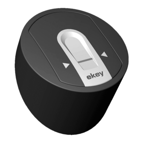
an ekey home set nger scanner integra into an ekey dLine set
Information sheet for converting

2
YOUR FINGER. YOUR KEY.
Conversion
ekey home set
nger scanner integra
ekey dLine set

3
The conversion is only possible for the ekey home nger scanner integra including its control panel.
It is not possible to replace the ekey nger scanner arte.
It is recommended to have the conversion carried out by specialist personnel.
In addition to the ekey home nger scanner integra, the cable transfer may also have to be removed so that you can
get to the control panel.
If the micro control panel is installed on the lock side, the complete multi-point lock must be removed and reinstalled,
which is labor-intensive and time-consuming.
There are two sets, which dier in the dierent adapter cables depending on the installed control panel (CP IN or CP
micro):
291021 ekey dLine ngerprint adapter set FS IN/CP IN
291022 ekey dLine ngerprint adapter set FS IN/CP micro
Therefore, it is important to know which control panel was in use.
Note: The ekey dLine control unit has only one relay. If an SE IN with two relays was installed, the scope of
functions will change.
YOUR FINGER. YOUR KEY.
Important information

4
Instructions for tters or electricians YOUR FINGER. YOUR KEY.
291021 ekey dLine ngerprint adapter set FS IN/CP IN
201001 ekey dLine ngerprint scanner incl. ekey dLine
ngerprint scanner adapter integra
291121 ekey dLine design element adapter integra SG
201201 ekey dLine control unit
291301 ekey dLine ngerprint scanner/control unit
adapter cable 0.13 m
291331 ekey dLine control unit adapter cable CP micro
0.13 m
291022 ekey dLine ngerprint adapter set FS IN/CP micro
201001 ekey dLine ngerprint scanner incl. ekey dLine
ngerprint scanner adapter integra
291121 ekey dLine design element adapter integra SG
201201 ekey dLine control unit
291301 ekey dLine ngerprint scanner/control unit adapter
cable 0.13 m
291332 ekey dLine control unit adapter cable CP micro 0.13 m
201001 291121 291301 291331 291332
201201

5
Optional – if a CP IN was installed, a suitable mounting plate:
101905 ekey mounting plate round-cut 20 x 272 mm
101906 ekey mounting plate round-cut 24 x 272 mm
101907 ekey mounting plate square-cut 20 x 272 mm
101908 ekey mounting plate square-cut 24 x 272 mm
Note: Use the correct faceplate depending on the faceplate width of the CP IN.
You must replace the ekey home nger scanner integra including the design element and
the respective control panel, CP IN or CP micro.
The wiring, the cable transfer and the motorized lock remain from the existing ekey system (ekey home).
What other parts do you need?
What do you have to replace?
What can remain in the door?
YOUR FINGER. YOUR KEY.

6
CP micro – from page 7 on
CP integra – from page 13 on
FS IN into ekey dLine ngerprint scanner – from page 18 on
Disconnect the devices from the power supply before you start removing them.
It may be that the ekey dLine control unit including the adapter cable does not have enough space.
With wooden doors, but also behind the cable transfer or the lock, the space is usually very limited.
First check whether the new parts have space before continuing the conversion.
Carry out the test mode as soon as the devices have been replaced and before they are installed in the door:
Restore the power supply. Wait until the top-left LED segment on the ekey dLine ngerprint scanner ashes blue.
Place any nger within 10 minutes on the sensor. The motorized lock switches.
Then disconnect the power supply again and complete the installation of the ekey dLine ngerprint scanner and
control unit.
How to replace the control panel
How to replace the nger scanner integra
Important information for the conversion
YOUR FINGER. YOUR KEY.

7
How to nd the CP micro YOUR FINGER. YOUR KEY.
There are several places where the CP micro could be installed: behind the cable transfer, on the plastic
faceplate (mounting plate) or on the locking side.

8
How to replace the CP micro
YOUR FINGER. YOUR KEY.
In most cases, the CP micro is located behind the cable transfer, so you have to remove it.
Pull out the adapter cable until the CP micro (in a
housing or heat-shrink tubing) is out.
Unplug both connection cables.

9
How to replace the CP micro YOUR FINGER. YOUR KEY.
Plug the two adapter cables (291301 and 291332) into the ekey dLine control unit.
In this case, you do not have to connect anything
to the 4-core motor plug.
Beware!
Remove the jumper
(without the jumper, the
output is a dry contact)

10
How to replace the CP micro YOUR FINGER. YOUR KEY.
Plug the existing adapter cable or A cable into the two adapter cables (291301 and 291332) in the door.
Hide the cables and the ekey dLine control unit back in the door.
Reinsert the cable transfer and screw it on.

11
How to replace the CP micro YOUR FINGER. YOUR KEY.
Unscrew the CP micro if it is located behind the plastic faceplate.
Remove the CP micro from the faceplate.
Unplug the two connection cables.
You can mount the ekey dLine control unit onto the existing mounting plate.
The rest of the replacement is now as described previously.

12
How to replace the CP micro YOUR FINGER. YOUR KEY.
If the CP micro is on the motorized lock side, the conversion is very time-consuming: In most cases, the complete
multi-point lock has to be removed.
Have the conversion carried out by specialist personnel only.
Apart from that, the procedure is the same as on the cable transfer side.

13
How to replace the CP integra YOUR FINGER. YOUR KEY.
The CP integra is located in the door rebate on the hinge side.
You must loosen the two fastening screws to remove the CP integra.
Pull out the CP integra and unplug all connection cables.

14
How to replace the CP integra YOUR FINGER. YOUR KEY.
Plug the two adapter cables (291301 and 291332) into the ekey dLine control unit and the A cable and the cable
from the cable transfer into the other ends.

15
How to replace the CP integra YOUR FINGER. YOUR KEY.
Connect the cores from the green plug to the 4-core plug for the connection to the motorized lock (labeled 1 2 3 4).
Connection according to wiring diagram:
In the case of locks that work with a switching impulse, you must switch from the green plug to the ekey dLine
plug as follows: 1 to 1, 2 to 2, 3 to 3. 4 remains free on the ekey dLine plug.
Beware!
Do NOT remove the
jumper
Color
ekey dLine cable transfer
Wiring diagram ekey dLine/GU-SECURY Automatic
Connection to the motorized lock
Connection to the electrical installation
Description
white VDC (+) (12-24)
brown GND (-)
green
yellow
blue
gray
pink
Input
red
Input Potential-free
request-to-exit
button for manual
door opening
Color
ekey bus
ekey bus
For testing purposes
For testing purposes
4
2
1
ekey dLine ngerprint
450007
ekey dLine cable FP
ekey dLine controller
450008
GU motorized lock cable
48 cm 2,5 m
201401
1
2
3
4
5
5
3
M
Connection to the control unit
Description
ColorPin
4 - -
3 black Switching impulse (+)
2 gray GND (-)
1 brown VDC (+)
Description
Pin
3black Switching impulse (+)
2gray GND (-)
1brown VDC (+) Risk of electrocution: All ekey devices
are to be operated with Safety Extra
Low Voltage (SELV). Only use power
supplies rated protection class 2 with
safety approval according to
EN 62368-1.
Failure to do so will create a risk of
fatal electrocution.
Only certied electricians are
authorized to carry out electrical
installation work on mains systems.
DANGER
ATTENTION
Property damage in the event of
incorrect mounting and wiring: The
system devices are operated using
electricity.
They could be destroyed if they are
mounted and wired incorrectly.
Mount and wire the system devices
correctly before connecting the
power.
Each unused core must be insulated separately!
This wiring diagram is not subject to
updating. We reserve the right to make
technical modications and change the
product‘s appearance; any liability for
errors and misprints is excluded.
NOTICE
ID360/746/0/712: Version 1, 2020-10-06
4321
Use the cable for the motorized lock from GU.

16
How to replace the CP integra YOUR FINGER. YOUR KEY.
Connect the cores from the green plug to the 4-core plug for the connection to the motorized lock (labeled 1 2 3 4).
Connection according to wiring diagram:
In the case of locks that work with a dry contact, you must switch from the green plug to the ekey dLine plug as follows:
1 to 3, 3 to 4. 1 and 2 remains free on the ekey dLine plug.
Beware!
Remove the jumper
(without the jumper,
the output is a dry
contact)
Wiring diagram ekey dLine/MACO A-TS
Connection to the motorized lock
Connection to the electrical installation
Description
white VDC (+) (12-24)
brown GND (-)
green
yellow
blue
gray
pink
Input
red
Input Potential-free
request-to-exit
button for manual
door opening
Color
ekey bus
ekey bus
For testing purposes
For testing purposes
4
2
1
5
3
M
Connection to the control unit
Risk of electrocution: All ekey devices
are to be operated with Safety Extra
Low Voltage (SELV). Only use power
supplies rated protection class 2 with
safety approval according to
EN 62368-1.
Failure to do so will create a risk of
fatal electrocution.
Only certi�ed electricians are
authorized to carry out electrical
installation work on mains systems.
DANGER
ATTENTION
Property damage in the event of
incorrect mounting and wiring: The
system devices are operated using
electricity.
They could be destroyed if they are
mounted and wired incorrectly.
Mount and wire the system devices
correctly before connecting the
power.
Each unused core must be insulated separately!
This wiring diagram is not subject to
updating. We reserve the right to make
technical modi�cations and change the
product‘s appearance; any liability for
errors and misprints is excluded.
NOTICE
ID368/757/0/718: Version 1, 2021-03-01
Description
ColorPin
4 yellow Opening signal
3 green Opening signal
2white VDC (+)
1 brown GND (-)
Description
ColorPin
4 green Opening signal
3 yellow Opening signal
2brown GND (-)
1white VDC (+)
4321
Jumper must be removed!
ekey dLine cable transfer
ekey dLine ngerprint
450007
ekey dLine cable FP
ekey dLine controller
450008
ekey dLine cable MT MACO
48 cm 2,5 m
201401
1
2
3
4
5
201351, 201352

17
How to replace the CP integra YOUR FINGER. YOUR KEY.
Attach the appropriate mounting plate to the ekey dLine control unit.
Stow the cables in the door leaf and screw the mounting plate back on.

18
How to replace the FS integra YOUR FINGER. YOUR KEY.
Remove the design element. Loosen the screws until the retaining clips have rotated to the side.
Remove the finger scanner.
Unplug the connection cable.

19
How to replace the FS integra YOUR FINGER. YOUR KEY.
Take the ekey dLine ngerprint scanner adapter for the integra nger scanner.
Plug in the A cable. The adapter for the A cable is on the RJ-45 plug.

20
How to replace the FS integra YOUR FINGER. YOUR KEY.
Insert the ekey dLine ngerprint scanner adapter for the integra nger scanner.
Screw it back on.
Stick on the design element and press rmly.
Other manuals for Home
3
This manual suits for next models
1
Other eKey IP Access Controllers manuals
eKey
eKey TOCAhome integra User manual
eKey
eKey Home CP WM 1 User manual
eKey
eKey home FS IN User manual
eKey
eKey ekey home CP WM 1 User manual
eKey
eKey FS UP User manual
eKey
eKey home Series User manual
eKey
eKey FS OM Crestron Series User manual
eKey
eKey Home User manual
eKey
eKey TOCAhome Installation instructions
eKey
eKey FS WM 2.0 User guide
Popular IP Access Controllers manuals by other brands

UNIVIEW
UNIVIEW OET-213H-BTS1 quick guide
Lock Control
Lock Control ST-980 Series Operation and installation manual

DESi
DESi PiKS FC 60 user manual
Honeywell
Honeywell NetAXS-123 user guide
TH COMMUNICATIONS
TH COMMUNICATIONS MZ11D7 quick start guide
Dahua Technology
Dahua Technology DH-PFM888S-AC user manual

