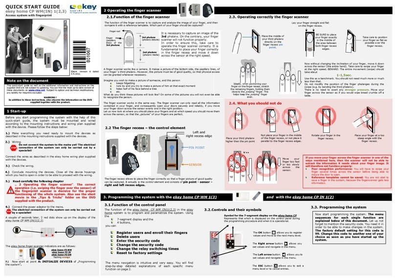
eKey FS UP User manual

1.
HINWEIS ZUM DOKUMENT
Diese Montageanleitung als auch die zusätzlichen Informationen und Anleitungen auf
der beiliegenenden DVD unterliegen keinem Änderungsdienst. Die letztgültige
Version dieser Dokumente finden Sie unter www.ekey.net. O tische und
technische Änderungen, Satz- und Druckfehler bleiben vorbehalten.
Bitte beachten Sie zu die er Anleitung unbedingt auch die Informationen
auf der beiliegenden DVD.
2.
LIEFERUMFANG
PRODUKT-GRUPPE FIN GER-
SCANNER
DICHTUN GS-
FLANSCH
EIN-
LEGETEIL
TRAG-
RIN G
SCHRAUBEN-
SATZ
MONTAGE-
ANLEITUNG
ARTIKEL-
NUMMER
PRODUKT-GRUPPE
101148
HOME
X X X X X X
101150
NET
Achtung!
Zum Betrieb
von ekey net
Finger canner
i t eine
SOFTWA RE-
LIZENZ
erforderlich!!
X X X X X X
101151 X X X X X X
101152 X X X X X X
101153 X X X X X X
101154 X X X X X X
101155 X X X X X X
101156 X X X X X
101157 X X X X X
101158 X X X X X
101159 X X X X X
101160 X X X X X
101161 X X X X X
DIE DEKORBLENDE UND DIE DEKORRAHMEN SIND NICHT
TEI L DES LIEFERUMFA NGES SONDER N MÜSSEN GESO NDER T BESTELLT WERDEN!
3.
WERZEUGLISTE ZUR MONTAGE
zur Montage de ekey FS UP benötigen Sie folgende Werkzeuge:
Schraubendreher
Schlitz 2.5mm
Abi olierzange
4.
CHECKLISTE ZUR MONTAGE EKEY HOME
1
.) Netz pannung ab chalten!
2.) Lieferumfang (Ver ackungsinhalt) rüfen (Ka .2.)
3.) sind der Dekorrahmen und der eventuell notwendige
Zwischenrahmen (50x50) Ihres Schalter rogrammes
vorhanden (Ka 5)
4.) haben Sie einen ekey net Fingerscanner, so benötigen Sie
zu dessen Betrieb eine SOFTWARE-LIZENZ. Haben Sie
diese noch nicht, so ordern Sie diese umgehend bei
Ihrem Partner.
5.) Ist die Dekorblende in der assenden Farbe vorhanden
(Ka 5)
6.) Unter utzdose ge rüft und montiert (Ka . 7)
7.) Verkabelung lt. Verkabelungs lan hergestellt
8.) Tragringstellung (A oder B) ermitteln und Tragring samt
Dichtungsflansch montieren (Ka . 5)
9.) Montageteile (Dekorrahmen der Schalterhersteller) in
Kabel einfädeln(Ka . 5)
10.) Terminierung an ekey FS UP ge rüft
11.) Terminierung an ekey SE REG ge rüft
12.) elektrischer Anschluss ekey FS UP herstellen
13.) Montage ekey FS UP (Feineinstellung der Höhe mittels
Einlegeteilen) und festschrauben (Ka . 5)
14.) Dekorblende aufschna en
15.) elektrischer Anschluss ekey SE REG herstellen
16.) elektrischer Anschluss Netzteil herstellen
17.) nochmalige Prüfung der gesamten Verkabelung
18.) Netz pannung ein chalten!
19.) Nehmen Sie das System mit Hilfe der Bedienung -
bzw. Kurzanleitung nun in Betrieb.
5.
MONTAGE EKEY FS UP
Abme ungen ekey FS UP
6.
SYSTEMKONFIGURATION UND MONTAGEHÖHE
EKEY FS UP
Beachten Sie bitte bei der Montage, da auf beiden Seiten de Finger canner
etwa eine handbreit Platz bleiben oll, um o e ine problem lo e Funkt ion de
Geräte mit allen Fingern zu gewährlei ten
7.
MINDESTABMESSUNGEN UP-DOSE
8.
REINIGUNG UND WARTUNG
9.
ENTSORGUNG
Au zug kompatible Schalterprogramme
In die folgende n Schalterprogramme der geli teten Her teller i t der ekey FS UP
einbaubar.
Sie brauchen üblicherwei e immer den Zwi c henrahmen für die Au nehmung
50x50.
Her teller Schalter-
programm
Di tanz
D [mm ]
Di tanz
E [mm]
Tragring-
montage
Stellung
Berker
B.1 9,9 4,5 A
K.1 10 4,5 A
K.5 10 4,5 A
S.1 10,2 4,5 A
Modul2 10,1 4,6 A
Bu h&Jaeger
Solo 11,7 6 B
Reflex SI 11 5,2 B
PUR 11,9 6,2 B
Future 11,6 6 B
Future linear 11,6 6 B
Axcent 11,6 6 B
Hager Kally so ur 10,4 4,7 A
Jung
CD500/ CD Plus 10 3,9 B
LS990 / LS Design 11,5 5 B
AS500 / A500 /
ACreation
10,6 4,5 B
Merten
ARTEC Edelsta hl 11,7 5,4 B
ARTEC 11,7 5,4 B
M-Star 10,5 4,4 B
1-M 11,2 4,4 B
M-Plan 10,5 4,4 B
Siemen Style 11,3 5,4 A
Die hier darge tellten Sc halterprogramme ind nur ein Au zug. Sie können den ekey FS
UP prinzipiell in jede Sc halterprogramm einbaue n, welche eine Au nehmung von 50 x
50 (mit oder ohne Adapterrahmen) be itzt.
10.
TECHNISCHE DATEN
Maximum Rating
Elektri che Eigen chaften
1) Stromaufnahme variiert m it Versorgungss ann ung ( Leistung saufnahme bleibt im Be reich ±10% konstan t)
2) Leistungsaufnahme variie rt ü ber ge samten Versorgungss an nungsbe reich ±10%
3) nur g ültig bei Einsatz der em fohlene n Kabel
11.
KONFORMITÄTNG UND KONFORMITÄT
Der ekey FS UP ents richt den Richtlinien 2004/108/EG(CE) und 2002/95/EC (RoHs)
Tec hni che Daten Einheit Werte
Ver orgung AC V 0-24
DC V ±30
Temperat urbereich
La ger °C -20 bis +75
Betrieb °C -20 bis +75
Tec hni che Daten
Ein-heit ekey FS UP ekey FS UP
indoor
Ver orgung (nur m it Sicherhe itstrafo =>
SELV )
AC V 8-24
DC V 8-24
Stromaufnahme [12VDC]
1
Ruhezustand mA 85
Matching m A 90
Lei tung aufnahme
2
Ruhezustand W ca. 1
Matching W ca. 1
Temperat urbereich La ger °C -20 bis +70
Betrieb °C -20 bis +70
Speicher Finger home: 99
Net: S(40), M(200), L(2000)
Sicherhe it FAR 1x 10
-6
FRR 1,4x 10
-2
Schutzart (im
ordnung gemäß
montierten Zu tand)
mit ekey fremdem
Schalterprogramm
IP33/IP43
mit ekey- Ra hmen IP44
Ge chwindigkeit s 1-4
Leben dauer Fingerscans max.10 Mio
max. Kommunikation Leitung länge (KLEMME
1,2)
3
m 500
max. Kommunikation Leitung länge (KLEMME
1,2)
3
bei Indu tr ieanwe ndung
m 30
max. Leit ung länge an Spannung ver orgung
bei Indu trieanwe ndung (K lemme 3,4)
m 30
Abme ungen LxBx T mm 50 x 50 x 35mm
Montage höhe cm 155
Montageanleitung
ekey FS UP
D24: 801329: Version 2
vom 9.12.2010
SCHNITT
D
E
Dekorrahmen
Zwischenrahmen
auf 50 x50
T ra gring
Zwi chenrahmen 50x 50.
abhängig vom Schalter ro gra mm
ist ein Zischenrahmen auf
50x50mm notwendig
Schrauben Sie de
n
ekey FS UP
am Tragring
entweder an den A- Positionen oder B
Positionen fest. A oder B ergibt sich aus der
Montage des Tragringes (siehe
Tragringmontage nebenstehend)
Unterschiedliche Hersteller von Schalter rogrammen haben auch verschiedene Abstände vom Tragring
bis zur Frontseite der Dekorrahmen. Damit der ekey FS UP möglichst lan mit der Frontseite
abschließt, ist es möglich diesen Abstand des ekey FS UP anzu assen.
grobe Anpa ung mit Tragringeinbau um 90° ver etzt.
Feinanpa ung mittel einem oder mehrerer Einlegeteileteile.
klein
Tragringmontage
(grobe Ab tand po itionierung)
A
B
Tragring von
Stellung A
um 90° drehen
=
Stellung B
Stellung B
= große Distanz
gross
Stellung A
= kleine Distanz
Dekorrahmen
Dekorblende
(nicht im Lieferumfang.
muss gesondert
bestellt we rden)
ekey FS up
Der Tragring ist in
Abhängigkeit des
Schalter rogra mms
einzubauen. Siehe
Tragringmontage
Kabel
Siehe Kabel-
emp fehlung
UP
-
Do e
nach
DIN49072 im
Mauerwerk
Dichtung flan ch
für Montage im
Außenbereich
unbedingt notwendig!
Dekorrahmen und Zwi chenrahmen
erhalte n Sie
bei Ihrem Elektrike r!
1.) Verwenden Sie Standard- Rahmen von
Schalterher tellern wie Bu h&Jäger,
Gira, Jung u w. So erre ichen Sie
maximal eine Scutzart vonIP33/IP43
(abhängig vom Schalterprogramm )
2.) ekey bietet einen eigenen Rahmen al
Zubehörteil an. Damit erre ichen Sie
eine Schutzart von IP44
Einlegeteil
Für Höhenan assung
35mm
50mm
50mm
Reinigung Sen or
Durchführung der Reinigung
Der Sensor ist grundsätzlich resistent gegen eine Vielzahl von Reinigungsmittel und
chem. Stoffe. Wir em fehlen aber trotzdem s eziell im Hinblick auf die
Fingerführung und die Dekorblende mit einem feuchten, weichen, nicht
kratzendenden(scheuernden) Tuch den Fingerscanner zu säubern. Zum Anfeuchten
des Tuches verwenden Sie bitte reines warmes Wasser.
Sensor
Fingerführung
Dekorblende
Der Sen or
Die Beschichtung des Sensors ist sehr widerstandsfest gegen chem. Einflüsse und
mechanische Belastung durch z.B. Staub :
Die Sensorfläche selbst ist gegen folgende Chemikalien resistent:
Reinigungsmittel( Seife, Armor All ( lastic cleaner / reservativ), Formula
409,..)
S eisen & Getränke (Cola,Kaffee,Juice…)
Alkohol
Verschmutzungen durch Öl ,Fett, Benzin, Bremsflüssigkeit…
Hand Lotion
Wartung
Ihr Fingerscanner ist grundsätzlich wartungsfrei. Ausnahme bildet eine
s
ichtbare
Verschmutzung am Sensor bzw. wenn die Erkennungsleistung sinkt. Führen Sie
in diesem Fall eine Reinigung des Sensors wie oben beschrieben durch.
Setzen Sie eine Unter utzdose nach
DIN 49072. Achten Sie dabei auf die
vorgeschriebene Montagehöhe von
ca. 155cm bzw 100cm!
Die Unter utzdose muss die
nebenstehenden Innenabmessungen
als Mindestgröße aufweisen (nach
DIN49072)
Innerhalb der Euro äischen Gemeinschaft wird für elek trisch betriebene Geräte die
Entsorgung durch nationale Regelungen vorgegeben, die auf der EU-Richtlinie
2002/96/EC über Elektro-und Elek tronik-Altgeräte (WEEE) basieren. Danach dürfen
alle nach dem 13.08.2005 gelieferte n Geräte , in den die ses Produkt e ingeordnet ist,
nicht mehr mit dem kommunalen oder Hausmüll entsorgt we rden. Für die hier
beschriebenen P rodukte gilt diese Ve rordnung.
mind.
3
(abhängig von
M otorsc hloss )
Die vorge chriebene
Montagehöhe für den
ekey FS UP
liegt bei
enkrechter Fingerführung bei ca. 155cm
waagrechter Fingerführung bei mind 100cm
Standfläche
Motor chlo
Kabelübergang
ca
155cm
bzw. 100cm
4
ekey FS UP
Netzteil
E
-
Verteiler
ekey SE REG
e
key home 1 SE REG
und
da Netzteil sind im
Schaltschrank zu montieren!
Nicht für jedes Schalter rogramm ist ein Einbau
lan mit dem
Dekorrahmen möglich. In diesem Fall wird der ekey FS UP den
Dekorrahmen nach vorne überragen.
Für ekey net Fingerscanner mit RFID-Kartenleser dürfen nur Dekorblenden
bzw. Gehäusefronten aus Kunststoff verwendet werden (ausgenommen
RFID s ezifiziertes
original ekey Zubehör
aus Metall
)

1.
REFERENCE NOTE FOR THIS DOCUMENT
This installation manual as well as the additional information rovided on the
accom anying DVD is not subject to u dating. The latest version of this document is
available for download under www.ekey.net. Subject to o tical and technical
change, ty esetting and rinting errors ex ected.
Related to thi manual, plea e pay pecial attention to the information
upplied on the accompanying DVD.
2.
DELIVERY SCOPE
PRODUKT-GRUPPE FIN GER
SCANNER
SEALING
FLANCH
MOUNT.
BRAC KET
INSERTS SCREW SET
INSTALL.
MANUAL
PART
NUMBER
PRODUCT GROUP
101148
HOME
X X X X X X
101150
NET
Attention!
To operate an
ekey net finger
canner you
are require to
purcha e a
SOFTWA RE
LICENSE!!
X X X X X X
101151 X X X X X X
101152 X X X X X X
101153 X X X X X X
101154 X X X X X X
101155 X X X X X X
101156 X X X X X
101157 X X X X X
101158 X X X X X
101159 X X X X X
101160 X X X X X
101161 X X X X X
THE BE ZEL A S WELL AS THE INSTALLATIO N FRA ME A RE NOT SUPPLIED WITHIN THE
DELIVERY SCOPE AND HAVE TO BE ORDERED SEPARA TELY!
3.
TOOLS REQUIRED FOR INSTALLATION
You will need below di p layed to ol to in ta ll your ekey FS O M:
Flat crew
driver 2.5mm
Wire tripper
4.
CHECK LISTE TO INSTALLATION EKEY HOME
1
.) Di connect the electrical upply (main )!
2.) Check the delivery sco e ( ackaging content) for
com leteness (Cha . 2)
3.) Do do have a bezel as well as – if necessary - a suitable
spacer (50 x 50) for your switch? (Cha . 5)
4.) In case you install an ekey net finger scanner, you will need
a SOFTWARE LICENSE for o eration. If you do not have any,
lease contact your reseller to urchase the corres onding
amount.
5.) Does your bezel have the correct colour? (Cha . 5)
6.) Back box (single gang box) checked and mounted (Cha 7)
7.) Have you wired the devices according to s ecifications ?
8.) Determine correct ositioning (A or B) for the mounting
bracket and osition the sealing flanch accordingly
(Cha . 5)
9.) Wire the com onents (switch manufacturer’s design frame)
(Cha . 5)
10.) Check bus termination (di switch) on ekey FS OM
11.) Check bus termination (di switch) on ekey CO DRM
12.) Establish electric wiring of the ekey FS OM
13.) Install ekey FS OM (fine tuning height) and
fasten ro erly (Cha . 5)
14.) Position bezel
15.) Establish electric wiring of the the ekey CP DRM
16.) Connect the ower su ly to socket
17.) Final check of all cables
18.) Re-connect the electrical upply (main )!
19.) To take the system into o eration, lease refer to the
operating manual res ectively the quick reference
guide.
5.
INSTALLATION EKEY FS OM
Dimen ion ekey FS OM
6.
SYSTEM CONFIGURATION AND INSTALLATION
HEIGHT FOR EKEY FS OM
Plea e make ure to have ufficie nt pace (palm) on bot h ide of the finger
canner to allow proper operat ion with a ll finger .
7.
MINIMUM DIMENSIONS FOR GANG BOX
8.
CLEANING AND MAINTAINANCE
1.
DISPOSAL
Excerpt of compatible witche
Plea e find below an excerpt of elected witch manufacturer who are compatible with
the ekey FS OM.
Generally peaking, you will need a pacer for a 50x50 mm opening.
Manufacturer Product range Di tanc
e D
[mm]
Di tance
E [mm]
Po ition
of the
bracket
Berker
B.1 9,9 4,5 A
K.1 10 4,5 A
K.5 10 4,5 A
S.1 10,2 4,5 A
Modul2 10,1 4,6 A
Bu h&Jaeger
Solo 11,7 6 B
Reflex SI 11 5,2 B
PUR 11,9 6,2 B
Future 11,6 6 B
Future linear 11,6 6 B
Axcent 11,6 6 B
Hager Kally so ur 10,4 4,7 A
Jung
CD500/ CD Plus 10 3,9 B
LS990 / LS Design 11,5 5 B
AS500 / A500 /
ACreation
10,6 4,5 B
Merten
ARTEC Edelsta hl 11,7 5,4 B
ARTEC 11,7 5,4 B
M-Star 10,5 4,4 B
1-M 11,2 4,4 B
M-Plan 10,5 4,4 B
Siemen Style 11,3 5,4 A
Above di played prod uct range corre pond only to an excerpt. A a matter of principle,
you can mount the ek ey FS OM in any witch with 50x 50 mm dime n ion (with or without
pacer.
2.
TECHNICAL DATA
Maximum rating
Electric propertie
1) Power in ut varies based on the su ly voltage ( ower consum tion will remain constant ±10%)
2) Power consum t ion will va ry over the entire su ly vol tage ra nge ±10%
3) An in ut signal can be t rigge red by sh ort-wi ring a dry relay out ut on P IN10 a nd 11. The conta ct can show a maximum
resistance fo r an ON signal and a minimum resistance for an OFF signal. The s tated values a ly for a minimu m su ly
voltage of 8VDC.
4) only valid when using the recomme nded cab les.
3.
CONFORMITYNG UND KONFORMITÄT
The ekey FS OM meets the guidelines 2004/108/EG(CE) and 2002/95/EC (RoHs)
Tec hnichal data Unit Value
Power upply AC V 0-24
DC V ±30
Temperat ur range On sto ck °C -20 u to +75
In o e ra tion °C -20 u to +75
Tec hni che Daten
Unit ekey FS
OM
ekey FS
OM indoor
Ver orgung (only u e SELV- Supply ) AC V 8-24
DC V 8-24
Power input [12VDC]
1
Passive sta te mA 85
Matching mA 90
Power con umpt ion
2
Passive sta te W ca. 1
Matching W ca. 1
Temperat ur range On stck °C -20 u to +70
In o e ra tion °C -20 u to +70
Memory Finger Home: 99
Net: S(40), M(200), L(2000)
Security FAR 1x 10
-6
FRR 1,4x 10
-2
IP rating (when
in talled according to
pecification )
ekey foreign de ign
frame
IP33/IP 43
ekey de ign frame IP44
Matching pee d s 1-4
Life expectancy Swi es max. 10 mio
Max. bu length for comm unication
(CLAMP 1,2)
4
m 500
Max. bu length for comm unication
(CLAMP 1,2)
4 in
indu trial e nvironment
m 30
Max. ca ble length for electric upply in indu trial
environme nt (CLAMP 3,4)
m 30
Dimen ion LxWxD mm 50 x 50 x 35mm
In tallation height cm 155
In tallation manual
ekey FS UP
Cleaning the en or
How to clean
Generally s eaking, the sensor is highly durable against a large number of
detergents and other chemical substances. With regard to the finger mould and the
bezel, we recommend using a soft rag and clean water, though.
Sensor
Fin
ger mould
Bezel
Sen or
The sensor coating is highly resistant against chemical susbstances and mechanical
damage e.g. dust.
The sensor surface is resistant against below written chemicals::
Detergent (soa , armor all ( lastic cleaner / reservativ), Formula 409,..)
Food (cola, coffee, juice, etc.)
Alcohol
Dirt (oil, grease, etrol, etc.)
Hand lotion
Maintainance
Your finger scanner does
normally
not require any maintainance.
The only exce tion
is a severe visible amount of dirt on the sensor, res ectively if the recognition rate
deteriotated. Clean the sensor following the instructions above.
Use a gang box according to DIN
49072.
Pay attention to the minimum
installation height of a rox. 155 cm
from ground level!
The gang box has to stick to the
minimum dimensions as outlined in
the drawing (DIN49072)
Within the Euro ean Union the dis osal of electrically o erated devices is regule d
by national regulations, which are based o n the EU directive 2002/96/EC for
waste e lectrical and electronic equi m ent (WEEE). Equi ment delivered after
Augst 13
th
, 2005 allowe d - in which this roduct is classified – must not be
dis osed with munici al o r household wa ste . This dis osal ist valid für the here
liste d roducts.
min. 3 (de ending on
motor
loc king s ystem)
The
ekey FS UP
ha to be in talled at a height of approximately
155cm vertical finger rece
100cm horizontal finger rece
Ground level
locking y tem
Cable tran fer
ca.
155cm
or
100cm
4
ekey FS UP
Power
Switch box
ekey CP
DRM
ekey home 1 SE REG
und
da Netzteil have to be
mounted in the switch box.
Your electrician can su ly you with both the de ign
frame and the pacer you need!
3.) If you use the basic frames of manufacturers
such a s Bush&Jä ger, Gira, Jung, etc. then you
will only be able to reach a rotection class of
IP33/43 (de ending on the switch model).
4.) ek ey offers, a mong o ther accessories, a frame
of its own which allows a rote ction class of
IP44.
S ec tio n
D
E
Design frame
S acer
50x50
Bracket
Spacer 50x50
De ending on the
res ective switch, a s acer
fo r 50x50mm
will be necessa ry
Tighten the
ekey FS OM
via screws either in
osition A or B. The final osition of A or B will
result from the direction of the mounting
bracket ( lease refer to the drawing below)
Different switch manufacturers will have different distances from the mounting bracket to the front side
of of the design frame. To level the ekey FS OM with the design frame, it is ossible to adjust and fine
tune the height in two ways:
Turn the mounting bracket by 90° for paced po itioning.
For fine adju tment , u e one or more in ert
In talling the mounting bracket
( paced po itioning)
A
B
Turn bracket in
osition A by
90° =
osition B
Position B
= large dista nce
large
small
Position A
= small distance
35mm
50mm
50mm
De ign frame
Bezel
(no t su lie d in the
delivery sco e. To be
ordered se erately)
ekey FS
OM
To install the
mounting bracket,
ay attention to the
res ective switch
dim ensions.
C
abl
e
Refer to cable
pec
Gang box
according
to DIN49072 to be
installed
Sealing flanch
Necessary for
installation in an
outdoor
environment.
In ert
fo r height adjustment
You might not be able to level the scanner and the
design
frame
with all switches. In this case, the ekey FS OM will stick out in
the front.
You may only use lastic bezels or cover lates together with
ekey net finger scanners featuring RFID card readers (exce t
for original ekey metallic accessories es ecially designed for
RFID).
D24/15: 801329: Version
2 vom 9. 12. 2010
Table of contents
Languages:
Other eKey IP Access Controllers manuals
eKey
eKey FS OM Crestron Series User manual
eKey
eKey Home User manual

eKey
eKey TOCAhome integra User manual
eKey
eKey TOCAhome Installation instructions

eKey
eKey Home User manual

eKey
eKey TOCAhome User manual
eKey
eKey Multi User manual
eKey
eKey Home Manual
eKey
eKey FS WM 2.0 User guide
eKey
eKey ekey home CP WM 1 User manual
