Contents
1. Introduction ..................................................................................................................................................... 5
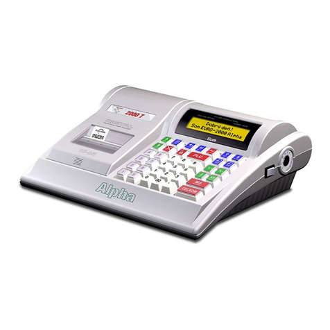
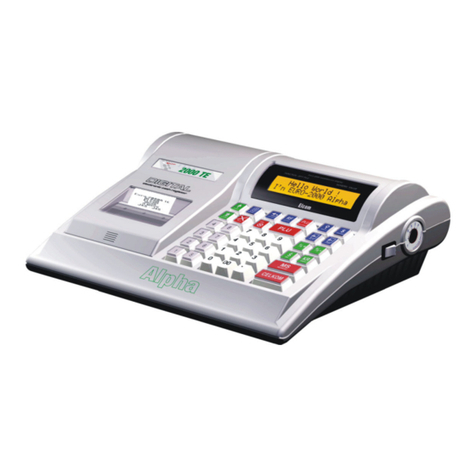
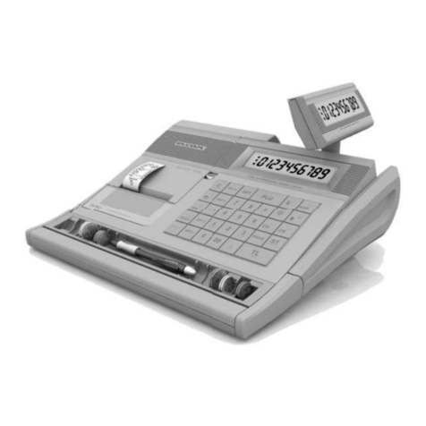
1.1. Euro-2000T Alpha/1000T specifications .......................................................................................................................... 5
1.2. System configuration ........................................................................................................................................................ 5
1.3. Block diagrams .................................................................................................................................................................. 6
2. Circuits description ........................................................................................................................................ 7
2.1. Power supply circuits ....................................................................................................................................................... 7
2.1.1. External power source ......................................................................................................................................... 7
2.1.2. Primary power circuit. ........................................................................................................................................... 7
2.1.3. Voltage regulator ................................................................................................................................................... 8
2.1.4. Printer power circuit.................................................................................................................................. ......... 8
2.1.5. Secondary power circuit ...................................................................................................................................... 9
2.1.6. Fiscal memory power circuit ................................................................................................................................. 9
2.1.7. Power voltages description ................................................................................................................................. 9
2.2. Microcontroller and its supporting circuits. .................................................................................................................... 10
2.2.1. Microcontroller E-2000N. ..................................................................................................................................... 10
2.2.2. Memory circuits. .................................................................................................................................................. 12
2.2.3. Reset system. ..................................................................................................................................................... 13
2.2.4. Real time clock circuit. ......................................................................................................................................... 13
2.3. I/O circuits. ...................................................................................................................................................................... 14
2.3.1. Printer control circuits. ........................................................................................................................................ 14
2.3.2. Keyboard. ............................................................................................................................................................ 16
2.3.3. Displays. .............................................................................................................................................................. 18
2.3.4. Euro-2000T Alpha control lock............................................................................................................................ 22
2.3.5. Communication circuits ....................................................................................................................................... 22
2.3.6. FM circuit connection .......................................................................................................................................... 25
2.3.7. Other circuits ........................................................................................................... ............................................ 25
3. Line thermal printer LT-286. ............................................................................................................................ 27
3.1. General specifications. ................................................................................................................................................... 27
3.2. Thermal head. ................................................................................................................................................................. 27
3.2.1. Thermal head constitution. .................................................................................................................................. 27
3.2.2. Head division processing. ................................................................................................................................... 28
3.2.3. Print data and print position ................................................................................................................................. 28
3.2.4. Specifications of thermistor ................................................................................................................................ 28
3.2.5. Timing chart. ........................................................................................................................................................ 28
3.3. Paper feed ....................................................................................................................................................................... 29
3.3.1. Specifications of stepping motor ........................................................................................................................ 29
3.3.2. Excitation sequence ............................................................................................................................................ 29
3.3.3. Motor control circuit ............................................................................................................................................. 29
3.4. Head-up sensor .............................................................................................................................................................. 30
3.5. Paper end sensor circuit ................................................................................................................................................ 30
3.6. Total timing chart ............................................................................................................................................................ .30
3.7. Connecting terminals ...................................................................................................................................................... 31
3.7.1. Thermal head terminal ......................................................................................................................................... 31
3.7.2. Motor and sensor terminal ............................................................................................................................ ......32
3.8. How to clean the thermal head ...................................................................................................................................... 32
4. Installation of modules ..................................................................................................................................... 33
4.1. Removing and installing the top cabinet ......................................................................................................................... 33
4.2. Lead acid accumulator replacement .............................................................................................................................. 35
4.3. Printer replacement ......................................................................................................................................................... 36
4.4. Winding motor replacement. ........................................................................................................................................... 37
4.5. Mainboard replacement. ................................................................................................................................................. 38
4.6. EPROM replacement. ...................................................................................................................................................... 39
4.7. SRAM replacement. ........................................................................................................................................................ 39
4.8. NiCd battery replacement. .............................................................................................................................................. 40
4.9. Keyboard replacement ................................................................................................................................................... 41
4.9.1. Euro-2000T Alpha keyboard replacement .......................................................................................................... 41
4.9.2. Euro-1000T keyboard replacement .............................................................................................................. ......42
4.10. Display replacement. ...................................................................................................................................................... 43
4.10.1.Euro-2000T Alpha alpha-numerical and segment display module replacement ............................................... 43
4.10.2.Euro-1000T display module replacement ..................................................................................................... ......44
4.11. Euro-2000T Alpha control lock replacement. ................................................................................................................. 45
4.12. Peripherals to mainboard connection . .......................................................................................................................... 46
4.12.1.Euro-2000T Alpha peripherals to mainboard connection .................................................................................. 46
4.12.2.Euro-1000T peripherals to mainboard connection ...................................................................................... ......47
3
© Elcom s.r.o.
Euro-2000T Alpha/1000T Service manual
