manuals.online logo
Brands
  1. Home
  2. •
  3. Brands
  4. •
  5. ELCOM
  6. •
  7. Cash Register
  8. •
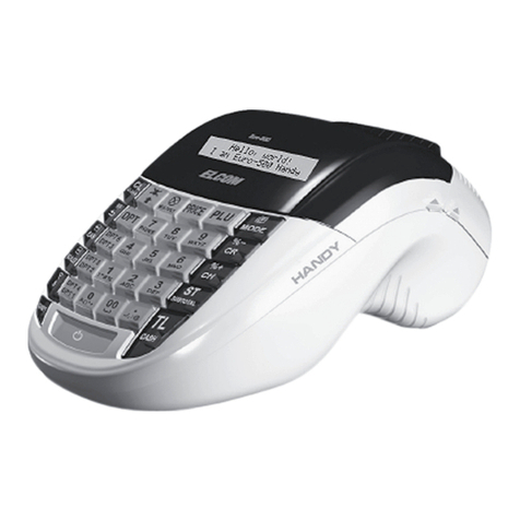
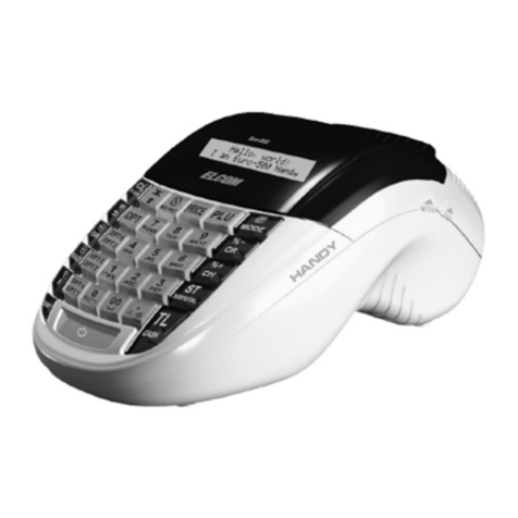
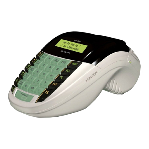
  9. ELCOM Euro-500T Handy User manual

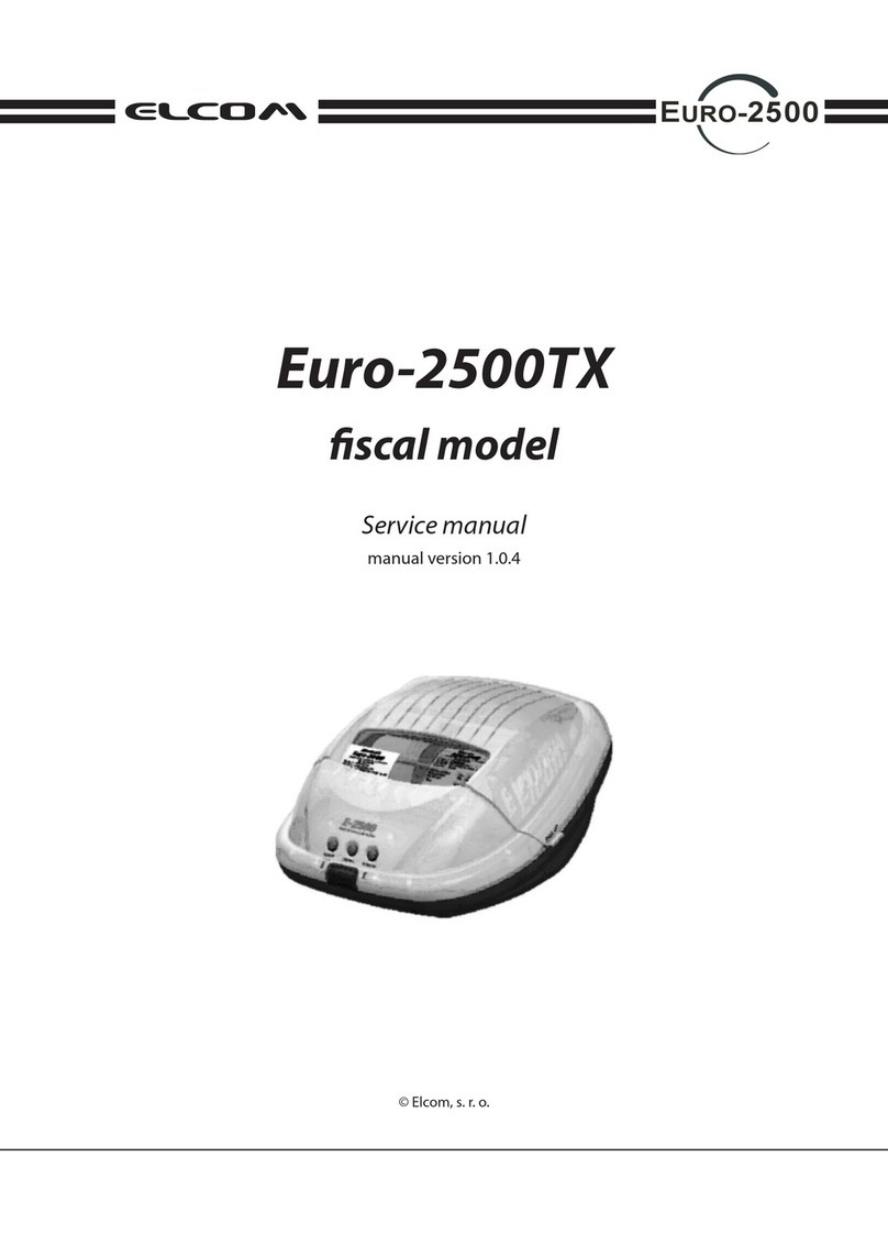
ELCOM Euro-500T Handy User manual

Euro-500T Handy
Service manual
© Elcom Ltd.
Version 1.0
Euro-500 Handy
Neither this manual, or any part of it, may be copied or distributed without
the consent of the Elcom company.
All rights of Elcom Ltd. are reserved.
© Elcom Ltd.
Service manual
3
Euro-500T Handy
Table of contents
1 INTRODUCTION ............................................................................................................................ 5
1.1 Euro-500T Handy cash register technical parameters ............................................................ 5
1.2 System configuration ................................................................................................................. 5
1.3 Cash register block diagram...................................................................................................... 5
2 CIRCUIT SCHEMES AND FUNCTIONS ........................................................................................ 6
2.1 Connection circuits .................................................................................................................... 6
2.1.1 External power supply ..................................................................................................... ............. 6
2.1.2 Primary connection circuit ............................................................................................................ 6
2.1.3 Voltage stabilizer .......................................................................................................................... 7
2.1.4 Printer connection circuit .............................................................................................................. 8
2.1.5 Secondary connection circuit ....................................................................................................... 8
2.1.6 Circuit for connecting the fiscal memory ....................................................................................... 9
2.1.7 Power supplies characterisation ................................................................................................... 9
2.2 Micro-controller and its support circuits ................................................................................ 10
2.2.1 E-500N micro-controller ............................................................................................................. 10
2.2.2 Memory circuits .......................................................................................................................... 12
2.2.3 System start and outage ................................................................................................... ......... 13
2.2.4 Current time circuit ..................................................................................................................... 13
2.3 Input-Output circuits ................................................................................................................. 14
2.3.1 Print control circuits .................................................................................................................... 14
2.3.2 Keyboard .................................................................................................................................... 16
2.3.3 Displays ..................................................................................................................................... 17
2.3.4 Communication circuits .............................................................................................................. 20
2.3.5 Interconnection of FM circuits ..................................................................................................... 21
2.3.6 Other circuits ............................................................................................................................. 22
3 THE MLT-288 THERMAL PRINTER ............................................................................................ 24
3.1 Basic layout ............................................................................................................................... 24
3.2 Thermal head ............................................................................................................................ 24
3.2.1 Thermal head composition ......................................................................................................... 24
3.2.2 Thermal head data processing ................................................................................................... 25
3.2.3 Print data and their position ........................................................................................................ 25
3.2.4 Thermistor layout ....................................................................................................................... 25
3.2.5 Time chart .................................................................................................................................. 25
3.3 Paper shifting ............................................................................................................................ 26
3.3.1 Stepping motor layout ................................................................................................................. 26
3.3.2 Excitation sequence ................................................................................................................... 26
3.3.3 Control circuit ............................................................................................................................. 26
3.4 Sensor of head position ........................................................................................................... 27
3.5 Sensors of paper ribbon end ................................................................................................... 27
3.6 Overall time chart ...................................................................................................................... 27
3.7 Printer connectors .................................................................................................................... 28
3.7.1 Thermal head connector ............................................................................................................ 28
3.7.2 Motor and sensors terminal ........................................................................................................ 29
3.8 How to clean thermal head ...................................................................................................... 29
4 MODULE (RE)INSTALLATION .................................................................................................... 30
4.1 Dismantling the cash register .................................................................................................. 30
4.2 Accumulator replacement ........................................................................................................ 32
4.3 Printer replacement .................................................................................................................. 33
4.4 Motor replacement .................................................................................................................... 34
4.5 Electronics mainboard replacement ....................................................................................... 35
4.6 EPROM replacement ................................................................................................................ 36
4.7 Replacement of damaged SRAM or replacement of SRAM with higher capacity .............. 36
4
© Elcom Ltd.
Service manual
Euro-500T Handy
4.8 NiCd battery replacement ........................................................................................................ 37
4.9 Keys and keyboard replacement ............................................................................................ 37
4.10 Replacement of displays .......................................................................................................... 39
4.10.1 Replacement of Euro-500T Handy (segment/segment) displays ................................................ 39
4.10.2 Replacement of Euro-500T Handy (alpha/segment) displays ..................................................... 40
4.11 Cash register connectors ........................................................................................................ 41
4.11.1 Connectors on mainboard of electronics ....................................................................................41
4.11.2 Connectors for connecting external appliances .......................................................................... 41
4.12 Back-light installation of segmented LCD display ................................................................ 42
4.13 Connecting of external drawer ................................................................................................ 43
4.14 Connecting of external keyboard ............................................................................................ 44
4.15 Interconnecting of Euro-500T Handy and PC through RS-232 interface ............................ 45
4.16 Connecting of scanner and scales through RS-232 interface ............................................. 45
5 CASH REGISTER TESTING ........................................................................................................ 46
5.1 Test of displays ......................................................................................................................... 46
5.2 Printer test ................................................................................................................................. 47
5.2.1 Testing of printing ....................................................................................................................... 47
5.2.2 Testing of scanning the thermal printer head position .................................................................. 47
5.2.3 Testing of paper ribbons sensors .......................................................................................... ...... 48
5.3 Keyboard tests .......................................................................................................................... 48
5.3.1 Keyboard test 1 .......................................................................................................................... 48
5.3.2 Keyboard test 2 .......................................................................................................................... 49
5.4 Communication interface tests ............................................................................................... 50
5.4.1 Test of RS-232C serial interface for the PC ................................................................................50
5.4.2 Test of RS-232C serial interface for the scanner and electronic scales ...................................... 50
5.4.3 The test of serial interface for the external PC keyboard ............................................................. 51
5.5 Test of cash register drawer .................................................................................................... 52
5.6 Fiscal memory tests .................................................................................................................. 52
5.6.1 Tests of data reading from the fiscal memory ............................................................................. 52
5.6.2 Test of data recording to the fiscal memory ................................................................................53
5.6.3 The operating voltage control for the fiscal memory .................................................................... 53
5.6.4 The test of the control signals I for the fiscal memory ................................................................. 54
5.6.5 The test of the control signals II for the fiscal memory................................................................. 54
5.7 Test of the control sum of EPROM memory ........................................................................... 55
5.8 Battery tests .............................................................................................................................. 55
5.8.1 The test of battery condition ........................................................................................................ 55
5.8.2 The test of VCC1 supply ............................................................................................................. 55
6 FAILURE REMOVAL .................................................................................................................... 56
6.1 Failures in supply section ........................................................................................................ 56
6.2 Failures of micro-processing system ..................................................................................... 57
6.3 Failures of print ......................................................................................................................... 58
6.4 Failures of visual display ......................................................................................................... 60
6.5 Failures of keyboard ................................................................................................................. 60
6.6 Failures of communication ...................................................................................................... 61
6.7 Failures of current date and time............................................................................................. 61
6.8 Other failures ............................................................................................................................. 61
7 THE LISTS OF PCB COMPONENTS .......................................................................................... 62
7.1 Classification of cash register components .......................................................................... 62
7.2 List of electronics mainboard components ........................................................................... 62
7.3 List of keyboard components..................................................................................................69
7.4 List of display segmented module components ................................................................... 69
7.5 List of components on board of connectors ......................................................................... 70
7.6 List of components on interconnection board ...................................................................... 70
7.6.1 List of components on interconnection board of Euro-500T Handy (segment/segment) .............. 70
7.6.2 List of components on interconnection board of Euro-500T Handy (alpha/segment) ................... 71
© Elcom Ltd.
Service manual
5
Euro-500T Handy
1 Introduction
1.1 Euro-500T Handy cash register technical parameters
The Euro-500T Handy is a portable electronic cash register with the following technical parameters:
primary connection external adapter 230 V, 50-60 Hz/12 V, 1200 mA
internal connection NiMh accumulator 7,2 V, 1500 mAh
or lead accumulator 6 V, 1200 mAh
maximum power consumption 10 W
micro-processing system 16-bit micro-controller, 256 kB EPROM, 128 or 512 kB
memory backup NiCd accumulator 3,6 V, 60 mAh
printer electrothermal, CITIZEN MLT-288
customer and cashier display 2x segmented LCD
alphanumeric LCD 2x20 characters for cashier, segmented LCD for customer
keyboard 30 regular keys and 1 double key
1.2 System configuration
The Euro-500T Handy is designed as a portable electronic cash register. The main parameters of a portable cash register are: low
weight, small size and a guarantee of longevity without an external connection.
The E-500N 16-bit micro-controller with 11 I/O ports and 2 portable channels is the center of the cash register. The cash register
program is stored in the 256 kB EPROM. Depending on the program version in EPROM memory, the micro-controller works with
RAM memory with a capacity of either 128 or 512 kB.
System contains:
connecting circuits
micro-processing system
current time circuit
reset controller (reset control circuit)
circuit controlling power supply value
keyboard interface
display interface
printer interface
RS-232 serial interfaces for PC, scanner and electronic scales
interface for connecting external PC keyboard
circuits for power reduction
circuit for drawer opening
circuit for scanning paper ribbon end
back-light of cashier display (optional for segment cashier display)
back-light of customer display (optional)
fiscal memory with support circuits (optional)
external accumulator - battery box (optional)
1.3 Cash register block diagram
EPROM
256 kB
SRAM
128 (512) kB
8-bit data bus
19-bit address busA 0 - A 1 8
D 0 - D 7
Current
time circuit
RS 232
interface for PC
RS 232 inter-
face for scanner
and scales
External
PC keyboard
Power voltage
checking
Paper ribbon
present
checking
Display
Fiscal
memory
Printer
Keyboard
Control bleeding
current circuit
MICROCONTROLLER
E-500N

Other manuals for Euro-500T Handy

2

Other ELCOM Cash Register manuals

ELCOM Euro-500TE User manual

ELCOM

ELCOM Euro-500TE User manual

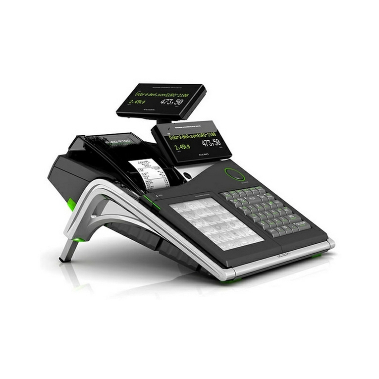
ELCOM Euro-2100TE User manual

ELCOM

ELCOM Euro-2100TE User manual

ELCOM Euro-2000T Alpha User manual

ELCOM

ELCOM Euro-2000T Alpha User manual

ELCOM Euro-150TE Flexy F User manual

ELCOM

ELCOM Euro-150TE Flexy F User manual

ELCOM Euro-2500 Series User manual

ELCOM

ELCOM Euro-2500 Series User manual

ELCOM Euro-500 Handy Series User manual

ELCOM

ELCOM Euro-500 Handy Series User manual

ELCOM Euro-2000TE Alpha User manual

ELCOM

ELCOM Euro-2000TE Alpha User manual

ELCOM Euro-1000M User manual

ELCOM

ELCOM Euro-1000M User manual

ELCOM Euro-100T User manual

ELCOM

ELCOM Euro-100T User manual

ELCOM Euro-2000M Alpha User manual

ELCOM

ELCOM Euro-2000M Alpha User manual

ELCOM Euro 500TE Handy User manual

ELCOM

ELCOM Euro 500TE Handy User manual

ELCOM Euro-2000T Alpha User manual

ELCOM

ELCOM Euro-2000T Alpha User manual

ELCOM Euro-2000T Alpha User manual

ELCOM

ELCOM Euro-2000T Alpha User manual

ELCOM Euro-2100TE User manual

ELCOM

ELCOM Euro-2100TE User manual

ELCOM Euro-50T Mini User manual

ELCOM

ELCOM Euro-50T Mini User manual

ELCOM Euro-50 User manual

ELCOM

ELCOM Euro-50 User manual

ELCOM Euro-2100 User manual

ELCOM

ELCOM Euro-2100 User manual

ELCOM Euro-2500T User manual

ELCOM

ELCOM Euro-2500T User manual

ELCOM Euro-1000T User manual

ELCOM

ELCOM Euro-1000T User manual

ELCOM Euro-200TE User manual

ELCOM

ELCOM Euro-200TE User manual

ELCOM Euro-200T User manual

ELCOM

ELCOM Euro-200T User manual

ELCOM Euro-150TE Flexy F User manual

ELCOM

ELCOM Euro-150TE Flexy F User manual

ELCOM Euro-50iTE Mini User manual

ELCOM

ELCOM Euro-50iTE Mini User manual

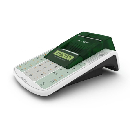
ELCOM Euro-500T Handy User manual

ELCOM

ELCOM Euro-500T Handy User manual

Popular Cash Register manuals by other brands

Royal 480nt operating manual

Royal

Royal 480nt operating manual

Olivetti ECR 8200 S user guide

Olivetti

Olivetti ECR 8200 S user guide

TEC TEC FS-3600 owner's manual

TEC

TEC TEC FS-3600 owner's manual

Integrated System Laboratory ISL 4006 user manual

Integrated System Laboratory

Integrated System Laboratory ISL 4006 user manual

Sam4s ER-380 Operation and program manual

Sam4s

Sam4s ER-380 Operation and program manual

Sharp XE-A206 Guía de inicio Rápido

Sharp

Sharp XE-A206 Guía de inicio Rápido

Samsung ER 5215 Operator's manual

Samsung

Samsung ER 5215 Operator's manual

Toast Toast Quick setup guide

Toast

Toast Toast Quick setup guide

QUORION CR 1200 user manual

QUORION

QUORION CR 1200 user manual

Olivetti ECR 7700 LD eco Plus user guide

Olivetti

Olivetti ECR 7700 LD eco Plus user guide

Sharp XE-A137-WH Operation Basic user manual

Sharp

Sharp XE-A137-WH Operation Basic user manual

Sharp XE-A203 - Cash Register Thermal Printing Graphic Logo... instruction manual

Sharp

Sharp XE-A203 - Cash Register Thermal Printing Graphic Logo... instruction manual

TEC TEC MA-1060 owner's manual

TEC

TEC TEC MA-1060 owner's manual

American Changer CLASSIC Series Operation manual

American Changer

American Changer CLASSIC Series Operation manual

Sharp XE-A130 Bedienungsanleitung

Sharp

Sharp XE-A130 Bedienungsanleitung

Sam4s ER-5100? SERIES Service manual

Sam4s

Sam4s ER-5100? SERIES Service manual

Casio PCR-T273 user manual

Casio

Casio PCR-T273 user manual

Sharp ER-2540 Service manual

Sharp

Sharp ER-2540 Service manual

manuals.online logo
manuals.online logoBrands
  • About & Mission
  • Contact us
  • Privacy Policy
  • Terms and Conditions

Copyright 2025 Manuals.Online. All Rights Reserved.