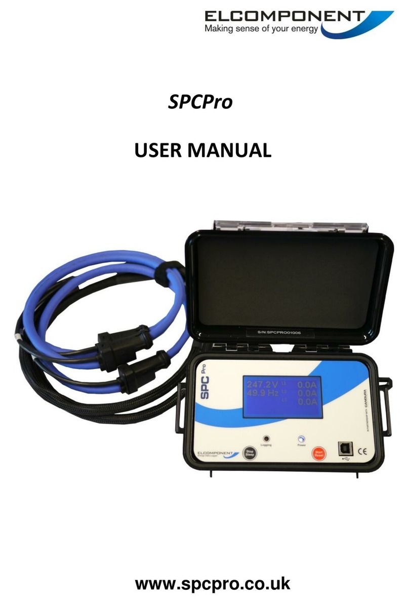
Elcomponent PQPro User manual

Copyright © 2012 ELCOMPONENT Ltd.
All Rights Reserved.
The information in this document is subject to change without notice.
Elcomponent has made every effort to ensure the accuracy of this manual. However, Elcomponent makes no
warranties with respect to this documentation and disclaims any implied warranties of merchantability and fitness
for a particular purpose. Elcomponent assumes no responsibility for any errors that may appear in this document.
Trademarks
PQPro and PV II are registered trademarks of Candura Instruments.
All other product names are copyright and may be trademarks and/or registered trademarks of their respective
companies.
Manufactured by:
Elcomponent Ltd
Unit 5 Southmill Trading Centre
Southmill Road Document number: CID1008.01
Bishop’s Stortford Date: 2 November, 2012
Herts CM23 3DY Printed in the UK
PQPro™User Manual

AEM35 Energy Meter
PQPro™User Manual
Table of Contents
Introduction.......................................................................................................................................1
Safety...............................................................................................................................................2
Quick Start........................................................................................................................................3
Hookup Configurations.....................................................................................................................4
Hookup Diagnostic Warnings...........................................................................................................5
PQPro™ Firmware Features............................................................................................................7
RMS and Waveform Data Storage.........................................................................................7
Harmonics ..............................................................................................................................7
Interharmonics........................................................................................................................8
Power Calculations.................................................................................................................8
Frequency...............................................................................................................................8
Event Capture ........................................................................................................................8
Under/Over Voltage Events....................................................................................................9
High Speed Voltage Transients .............................................................................................9
Current Inrush ........................................................................................................................9
Voltage and Current Unbalance.............................................................................................9
PQPro™ Back Panel......................................................................................................................10
PQPro™ Front Panel .....................................................................................................................11
PQPro™ Operation ........................................................................................................................12
Turning On and Off...............................................................................................................12
Memory Card........................................................................................................................12
PQPro™ Setup ..............................................................................................................................13
Phase CT Range..................................................................................................................13
CH 4 CT Range....................................................................................................................13
Connection ...........................................................................................................................13
1P2W - 1 Phase 2 Wire .............................................................................................................13
1P3W - 1 Phase 3 Wire (Edison circuit).......................................................................................13
3P3W - 3 Phase 3 Wire (Delta circuit) ........................................................................................13
3P4W - 3 Phase 4 Wire (Wye circuit)..........................................................................................13
2.5E - 2½ Element ....................................................................................................................13
PQPro™ Data Storage...................................................................................................................14
Storage Rate ........................................................................................................................14
Recording Mode...................................................................................................................14
Interharmonics......................................................................................................................15
Voltage Spike Waveforms....................................................................................................15
Under/Over Voltage Waveforms ..........................................................................................15
Current Inrush Waveforms...................................................................................................15
RMS Capture........................................................................................................................15
PQPro™ Trigger Levels .................................................................................................................16
Event Enable........................................................................................................................16
Phase Current Inrush ...........................................................................................................16
Channel 4 Current Inrush.....................................................................................................16
Phase Voltage Nominal........................................................................................................16
Channel 4 Voltage Nominal..................................................................................................16
Voltage Spike .......................................................................................................................16
Phase Voltage Over .............................................................................................................16
Phase Voltage Under...........................................................................................................17
Channel 4 Voltage Over.......................................................................................................17
Channel 4 Voltage Under.....................................................................................................17

AEM35 Energy Meter
PQPro™User Manual
PQPro™ Operation – Setup (continued) .......................................................................................17
Ext PT/CT.............................................................................................................................17
System Freq.........................................................................................................................17
Clock.....................................................................................................................................17
Bluetooth ..............................................................................................................................17
Calibrate...............................................................................................................................18
Language..............................................................................................................................18
Display..................................................................................................................................18
Record..................................................................................................................................19
Specifications.................................................................................................................................20

- 1 -
PQPro™User Manual
Introduction
The PQPro™ is the third generation of power quality analyzers developed by Elcomponent for the
measurement of power quality and for power system diagnostics. From the instrument’s front panel or,
for more detail use Elcomponent’s PV II™software, you can view:
▪AC and DC Voltage, Current, Power and Frequency
▪Waveforms, harmonics and vector diagrams for both voltage and current
▪Three phase voltage and current unbalance
▪Voltage sags and swells
▪High speed voltage transients
▪Current inrush
▪Flicker (IEC 61000-4-15)
▪Power Quality (IEC 61000-4-30 Class A)
The PQPro™ is an 8 channel power quality analyzer / data recorder. It monitors three phases of voltage
and current as well as a fourth channel of voltage and current. Measured parameters are updated every
½ cycle to ensure that nothing is missed. Most measurements can be viewed on the front panel LCD in
the field and recorded data can be transferred to a computer using the removable memory card. The
instrument is powered from the V1 voltage measurement input, or if V1 is a weak source, an auxiliary
power supply may be used. The PQPro™ has an internal rechargeable battery that can power the
instrument for up to 4 hours in the event of a power outage. The entire unit is enclosed in a rugged
weather proof case for use in harsh environments.

- 2 -
PQPro™User Manual
Safety
Although this instrument is designed to be as safe as possible, safety is ultimately the responsibility of
the operator. This instrument should only be operated as specified by the manufacturer and by
authorized personnel.
Please read and UNDERSTAND the following information before operating this instrument
▪The PQPro™ uses a membrane keypad that could be damaged if a sharp object is brought into
contact with it.
▪Frequently inspect the test leads and the instrument for damage. If the instrument shows any signs
of physical damage or functions improperly, it should not be used. Clean with a damp cloth only.
▪Never work alone. Ensure that a qualified observer is mindful of your activities.
▪When performing any measurements, all connections should be made to the circuits while the
power is off. To ensure personnel safety, the test leads and related connectors should not be
handled while the circuit is energized.
▪Do not attempt to measure any voltage higher than the maximum rating of 600V RMS. Failure to
observe the maximum rating could result in damage to the equipment or personnel injury.
▪Refer servicing of this instrument to qualified personnel only. Disconnect supply power before
servicing. Potentially lethal voltages may be present inside the case. If any of the protective circuitry
is improperly repaired, the safety of this product could be compromised.
▪Do not expose the PQPro™ directly to outdoor elements.
▪The following international symbol is used on the equipment and in this manual:
See explanation in manual to find out the nature of
the potential HAZARD and any actions to be taken.

- 3 -
PQPro™User Manual
Quick Start
Connecting the PQPro™ to the circuit to be measured is a straightforward process.
1. Connect the voltage leads for each phase to be measured. For proper operation V1 must always be
used. Three phase circuits can be connected in either a ‘wye’ or 'delta’ configuration. Refer to the
‘Hookup Configurations’ section for the various methods of connecting the voltage leads.
2. Connect the clamp CTs or flex CTs. Channels 1, 2 and 3 must use the same type and rating of CT,
channel 4 may use a different type and/or rating CT (Ensure that the correct CTs have been selected
in the SETUP menu).
3. Turn the instrument on by pressing the On/Off button.
4. Ensure a memory card is installed.
5. Use the ‘SETUP’ key and function keys to check and modify any of the setup parameters.
6. Press the ‘Record’ key and then F1 to start recording synchronized to the real time clock or F2 (if
recording interval is continuous) to start recording immediately. If there are any error messages,
please refer to the ‘Hookup Diagnostic Warnings’ section.
7. The measured values can be viewed from the instrument using the 'DISPLAY' key and function keys.
8. To stop recording press the ‘RECORD’ key and then F2 followed by F1 to confirm the stop command.
Note: Static discharges may occur when connecting leads or the memory card,
depending on environmental conditions. This is not hazardous and will not damage
the instrument. However it may affect the integrity of the data if the instrument is
recording. Connection and disconnection of leads etc. should be done while the
instrument is not recording. Before handling an instrument that is recording the
operator should discharge any potential static by touching a grounded object.
9. Data is transferred to a computer using the memory card. When recording has been stopped the
memory card can be removed from the instrument. The memory card can be inserted directly into
an SD card reader. Run PV II™and select 'File', 'Open' and then go to the drive that has been
configured for the memory card. If there is data on the card you will then see a file that can be
opened. After opening the file on the data card the file is processed and stored on the computer’s
hard drive.
Retract Shroud to Release

- 4 -
PQPro™User Manual
Hookup Configurations
The PQPro™ can be used to monitor any single phase or three phase power configuration. Following are
descriptions of the five most common field setups:

- 5 -
PQPro™User Manual
Hookup Diagnostic Warnings
From the ‘RECORD’ screen the operator can select ‘SYSTEM CHECK’. The instrument does a number of
checks on the connected signals, if it detects a potential problem a message will be displayed in the
RECORD screen. The operator can elect to ignore these messages and start anyway in which case these
messages will not appear while the instrument is recording. If the operator makes changes to the
instrument setup or the connections to the power system and the condition clears then the messages
will clear when the operator selects ‘SYSTEM CHECK’ again.
Possible messages and descriptions:
‘CH1 VOLTAGE TOO LOW’
‘CH2 VOLTAGE TOO LOW’
‘CH3 VOLTAGE TOO LOW’
Voltage being measured is less than 10V
‘CH1 VOLTAGE TOO HIGH’
‘CH2 VOLTAGE TOO HIGH’
‘CH3 VOLTAGE TOO HIGH’
‘CH4 VOLTAGE TOO HIGH’
Voltage being measured is greater than 120% of rated value.
‘CH1 CURRENT TOO HIGH’
‘CH2 CURRENT TOO HIGH’
‘CH3 CURRENT TOO HIGH’
‘CH4 CURRENT TOO HIGH’
Current being measured is greater than 120% of the CT rating.

- 6 -
PQPro™User Manual
‘-VE POWER CHECK CT1’
‘-VE POWER CHECK CT2’
‘-VE POWER CHECK CT3’
‘-VE POWER CHECK CT4’
This usually means that the relevant CT has been connected in reverse. To fix the problem
remove the CT, rotate it 180 degrees, reconnect it and then press ‘SYSTEM CHECK’ again. In
some cases this is not an error (i.e. when measuring a generator output).
‘VOLTAGE PHASE SEQ ERROR’
Voltage phase sequence is checked when voltage on channels 1, 2 and 3 are greater than 30V
and error occurs when phase sequence is not A B C. To fix this problem, swap the voltage
connections to channels 2 and 3 and then press ‘SYSTEM CHECK’ again.
‘CURRENT PHASE SEQ ERROR’
Current phase sequence is checked when currents on channels 1, 2 and 3 are greater than 5% of
range and error occurs when phase sequence is not A B C. To fix this problem exchange CT’s for
channels 2 and 3 and then press ‘SYSTEM CHECK’ again.
‘VOLTAGE OUTSIDE TRIG WINDOW’
This indicates that at least one of the four measured voltages is above the over voltage trigger
level or at least one of channels 1, 2 or 3 voltage is below the under voltage trigger level.
Note: Channel 4 under voltage is not included in the system check.
‘CURRENT GREATER THAN TRIG LEVEL’
This indicates that one or more currents are greater than the current inrush threshold.
‘CT TYPE ERROR - PHASE’
The type of CT (Flex or Clamp) connected to the phase CT inputs is not the same as selected.
‘CT TYPE ERROR - CHANNEL 4’
The type of CT (Flex or Clamp) connected to channel 4 inputs is not the same as selected.

- 7 -
PQPro™User Manual
PQPro™ Firmware Features
RMS and Waveform Data Storage
The PQPro™ stores RMS data at set intervals which can be adjusted from 0.2 (continuous) to 30 seconds
or 1 to 30 minutes. The minimum, maximum and average values are stored at the end of each storage
interval. The averaged values are calculated from the sum of the RMS values (updated every ½ cycle)
over the preceding storage interval. The minimum and maximum values are updated every ½ cycle over
the preceding storage interval.
The PQPro™ has a continuous store mode which stores RMS minimum, maximum and average data
every 200 milliseconds and waveform data continuously. During continuous store mode event capture
functions are disabled, and Bluetooth communication is disabled.
Data is stored in files with a maximum size of 409M. There are two different implementations of the
continuous store function.
For data cards 64G and larger the Connection Type is set to 3P4W (3P3W systems may be
measured but the power measurements will not be correct) and three channels of voltage and
three channels of current data are stored. The Storage Mode is automatically set to ‘Restart
When Full’. When the maximum file size of 409M is reached a new file is automatically started
until the card is full. The user may stop recording at any time. There is no gap in waveform data
between the end of one file and the start of the next file. At 60 Hz it will take 3.3 days to fill a
64G data card.
For data cards 32G and smaller the Connection Type and Storage Mode are user configurable. If
the user selects a Storage Mode of ‘Circular’ then the PQPro™ will keep recording until the user
stops recording. When the 409M file is full the oldest data will be overwritten. At 60 Hz a full
file will have 28 minutes of data. If the user selects a Storage Mode of ‘Restart When Full’ there
will be a small gap in the waveform data between the end of one file and the start of the next
file.
Harmonics
The PQPro™ displays up to the 41st harmonic on its display while the software displays up to the 128th
harmonic. Total Harmonic Distortion (THD) is calculated as the ratio between the square root of the
squared sum of the harmonic magnitudes (for harmonics 2…128) divided by the fundamental value. THD
is calculated over a 200 millisecond window.

- 8 -
PQPro™User Manual
Interharmonics
Interharmonics are calculated by the software from the waveform snapshots that are stored every
storage interval. The Interharmonic calculation requires multiple cycles of waveforms. If Interharmonics
are turned off only one cycle of waveforms is captured and the software can only calculate the
harmonics. If Interharmonics are turned on 10 cycles (for 50 Hz systems), 12 cycles (for 60 Hz systems)
or 40 cycles (for 400 Hz systems) are stored every storage interval. Interharmonics can be resolved to 5
Hz resolution from 10 cycles or 12 cycles and to 10 Hz resolution from 40 cycles.
In Continuous storage mode the 10 cycles, 12 cycles or 40 cycles of waveforms are stored continuously
with no missing cycles. This enables the software to be able to calculate Interharmonics over a longer
period. For example the software could use 120 cycles resulting in a resolution of 0.5 Hz (in 60 Hz
systems) for the Interharmonics. Note that in Continuous storage mode there is no option to turn
Interhamonics On or Off.
Power Calculations
The power calculations are updated every ½ cycle. The average values of power are recorded. Power
factor displayed is the true power factor (not the displacement power factor which is determined from
the phase angle shift between fundamental values of voltage and current) and is calculated as the ratio
of the real power (kW) divided by the apparent power (kVA).
Frequency
The system frequency is measured from the signal on V1 input. Frequency will not be measured if the
voltage is below 10V.
Event Capture
Under/over voltage events, high speed voltage transients and current inrush events are stored when
they occur. The trigger levels are set from the Setup menu under ‘TRIGGER LEVELS’. When an event is
triggered data for all four voltage and current channels is stored, if configured for a 3 phase system,
irrespective of which channel triggered the event.

- 9 -
PQPro™User Manual
Under/Over Voltage Events
Under/over voltage events are tagged as sags/swells if they are under 2 seconds in duration and
under/over if they are longer. The PV II™ software reports their duration in number of cycles,
with ½ cycle resolution, for events less then 2 seconds and in seconds for longer events. The
PQPro™ uses a hysteresis value of 0.1% of full scale to determine when the event has finished.
For example if the under voltage trigger level is set at 228.0 volts the instrument will start
recording an event when the voltage goes under 228.0 volts and will stop recording the event
when the voltage goes over 228.8 volts. For under/over voltage events both event waveforms
and RMS data, with ½ cycle resolution, are recorded. Pre-trigger data is ¼ of the event buffer for
waveforms and 64 cycles for RMS data. The Event Waveform buffer is user adjustable between
4 and 100 cycles. The Event RMS buffer is user adjustable between 120 and 3600 cycles.
Under/Over Voltage and Current Inrush events have the same Waveform and RMS buffer
lengths.
High Speed Voltage Transients
The PQPro™ captures high speed voltage transients that are 20 microseconds (50Hz) / 16
microseconds (60Hz) / 39 microseconds (400Hz) or longer. When a transient is detected on any
of the four voltages, high resolution (1024 samples/cycle) waveform data is stored. Only
waveform data for all voltage and current channels is stored with a user adjustable buffer of
between 2 and 10 cycles. Pre-trigger recording is fixed to ½ cycle.
Current Inrush
Current inrush data for all voltage and current channels is stored when the current on any of the
four channels exceeds the threshold setting. The trigger level setting for channel 4 can be set
independently from channels 1,2 and 3. Both event waveforms and RMS data, with ½ cycle
resolution, are recorded. Pre-trigger data is ¼ of the event buffer for waveforms and 64 cycles
for RMS data. The Event Waveform buffer is user adjustable between 4 and 100 cycles. The
Event RMS buffer is user adjustable between 120 and 3600 cycles. Under/Over Voltage and
Current Inrush events have the same Waveform and RMS buffer lengths.
Voltage and Current Unbalance
This is for three phase systems. Unbalance is calculated as the ratio of the negative sequence
component divided by the positive sequence component. Unbalance is calculated over a 200 millisecond
window.

- 10 -
PQPro™User Manual
PQPro™ Back Panel
The voltage and current connections are colour coded according to phase and polarity (for voltage).
Channel 1 or Phase A
Red
Channel 2 or Phase B
Yellow
Channel 3 or Phase C
Blue
Channel 4 Current
Grey
Channel 4 Voltage
White
There is an auxiliary connector that is used to connect to an external DC power supply (for use when V1
is connected to a weak source).
When measuring less than 4 voltages V1 must always be used. V1 zero crossing is used to synchronize
the data sampling and measure frequency. In the event of an outage on V1 the logger has an internal
digital phase lock loop that simulates the zero crossing until V1 is restored.

- 11 -
PQPro™User Manual
PQPro™ Front Panel
The front panel of the PQPro™ has a colour graphics display, a 10 button keypad and a memory card
interface.
The colour graphics display is 270x480 pixels.
The keypad has two types of buttons. The bottom row of 4 keys are fixed function buttons and the top
row of 6 keys are function keys that change function depending on the active screen on the display. In
most screens the bottom line of the display is used to describe the functions associated with the six
function keys.
The memory card interface is used to store recorded data on a memory card and also to load new
firmware. The PQPro™ will not begin a survey without a memory card installed. Once a survey has
been started the memory card may not be removed until the survey has been stopped.

- 12 -
PQPro™User Manual
PQPro™ Operation
Turning On and Off
The PQPro™ has a dedicated On/Off button. If the instrument is running on battery power, is not
recording and there has been no key pressed or Bluetooth activity for two minutes the instrument will
automatically turn off in order to conserve battery capacity. If the instrument is running on battery
power and recording is on the instrument will not turn off until the battery capacity is below 15%. At
that time the data file will be closed and the instrument will automatically turn off –no data will be lost.
After turning off due to low battery voltage the battery will have enough capacity to keep the real time
clock functioning for over a month.
Memory Card
The PQPro™ continually checks the memory card interface to see if a card has been inserted or
removed. When it detects a card being inserted (or a card in the socket immediately after power up)
the instrument checks the card size and the number of files on the card. The PQPro™ supports from
2GB to 64GB SD memory cards. Each file is allocated approximately 0.5GB on the card so that a 2GB
card can hold up to 4 data files and a 64GB card can hold up to 128 data files.
When the instrument detects a card being removed it changes the screen to the initial screen if the
instrument was not recording. If the instrument was recording when the memory card is removed
recording is stopped and an error message is displayed:
MEMORY CARD REMOVED WHILE RECORDING
RECORDING STOPPED
RE-INSERT CARD TO CLOSE FILE PROPERLY
If the memory card is not re-inserted the data file on the card will have the name Q999XXXX.TSQ and PV
II™ software may be able recover the trend data.
The Memory card should NEVER be removed while recording is on, ALWAYS stop
recording before removing the Memory card.
The Memory card offers a fast and convenient method to transfer recorded data to a computer. To
transfer data from the memory card to a computer, remove the card from the logger and insert into an
SD card reader. Run PV II™ and select 'File', 'Open' and then go to the drive that has been configured for
the memory card. If there is data on the card you will then see a file that can be opened. After opening
the file, the processed file can be saved on the computer’s hard drive.

- 13 -
PQPro™User Manual
PQPro™ Setup
Pressing the ‘SETUP’ button calls up the main setup screen. From the main setup screen you can select:
PHASE CT RANGE
CH 4 CT RANGE
CONNECTION
DATA STORAGE
TRIGGER LEVELS
EXT PT/CT
SYSTEM FREQ
CLOCK
BLUETOOTH
CALIBRATE
LANGUAGE
Phase CT Range
User selects the clamp CT or flex CT that is being used on channels 1, 2 and 3. The same type and rating
is used for all three channels.
CH 4 CT Range
User selects the clamp CT or flex CT that is being used on Ch 4. The type and rating can be different
from the phase CT.
Connection
User selects the type of phase connection, in all configurations channel 4 voltage and current is
recorded:
1P2W - 1 Phase 2 Wire
User can select 1, 2, 3 or 4 CTs to be associated with V1 in order to monitor multiple single phase
loads
1P3W - 1 Phase 3 Wire (Edison circuit)
Channels 1 and 2 for voltage and current are used for monitoring a residential type split phase
service.
3P3W - 3 Phase 3 Wire (Delta circuit)
Line to line voltages (Vab, Vbc and Vca) and line currents (Ia, Iband Ic) are measured directly. Only Ia
and Ic are required for three phase power calculations.
3P4W - 3 Phase 4 Wire (Wye circuit)
Line to neutral voltages (Van, Vbn and Vcn) and line currents (Ia, Iband Ic) are measured directly
2.5E - 2½ Element
Line to neutral voltages (Van and Vcn) and line currents (Ia, Iband Ic) are measured directly. Line
to neutral voltage Vbn is calculated from Van and Vcn.

- 14 -
PQPro™User Manual
PQPro™ Data Storage
User can configure various data store parameters:
▪STORAGE RATE
▪RECORDING MODE
▪INTERHARMONICS
▪VOLT SPIKE WVFRM (Voltage Spike Waveforms)
▪VOLT U/O WVFRM (Under/Over Voltage Waveforms)
▪CURR INRSH WVFRM (Current Inrush Waveforms)
▪RMS CAPTURE
Storage Rate
The storage rate has the following settings:
30, 15, 10, 5, 1 minute
30, 15, 10, 5, 1 second
Continuous
RMS calculations are updated every ½ cycle using a sliding one cycle window. At each storage
interval the minimum, maximum and average RMS values based on the ½ cycle update are
stored. For Continuous storage rate the RMS values are stored every 200 (50 or 60 Hz systems)
milliseconds, or every 200 milliseconds (400Hz systems). Event capture and Bluetooth
communication are disabled.
Waveforms for each channel are stored every storage interval. For storage rates 1 second or
longer one cycle of waveforms are stored if interharmonics are turned off and 10 cycles (50 Hz
systems), 12 cycles (60 Hz systems), 40 cycles (400Hz systems) if interharmonics are turned on.
For Continuous storage rate 10 cycles (50 Hz systems) or 12 cycles (60 Hz systems) of waveforms
are stored every 200 milliseconds. For 400 Hz systems and continuous storage rate 40 cycles of
waveforms are stored every 100 milliseconds.
Recording Mode
There are three different recording modes:
Stop when full
When the data file is full (approximately 409MB) recording is turned off.
Circular
When the data file is full newer data overwrites the oldest data. Trend data is stored separately
from event data so it is possible that Trend data could be full while event data is not resulting in
recorded events that occur prior to the start of the recorded Trend data.

- 15 -
PQPro™User Manual
Restart when full
When the data file is full the file is closed and a new file is automatically started. For storage
rates 1 second or longer the new file will start on an even minute boundary so there could be a
gap of up to a minute between the end of one data file and the start of the next one. For
continuous storage rate with data cards 32G or smaller the new file will start immediately with a
1 to 2 second gap between the end of one data file and the start of the next one. For continuous
storage with data cards 64G or higher the new file will start immediately with no gap. When the
memory card is full or when the Stop button is pressed, recording will stop.
Interharmonics
Interharmonics are calculated by the software from the waveform snapshots that are stored
every storage interval. If Interharmonics are turned off one cycle of waveforms are stored every
storage interval and the software can only calculate the harmonics. If Interharmonics are
turned on then multiple cycles of waveforms are stored every storage interval, 10 cycles (for 50
Hz systems), 12 cycles (for 60 Hz systems) or 40 cycles (for 400 Hz systems).
Interharmonics use a lot of memory and should only be used if required. For example, in a 60
Hz system at 1 minute storage it will take 45 days to fill a data file with Interharmonics off and
4..0 days with Interharmonics on. On power up Interharmonics are off and the user must turn
on Interharmonics if desired
Voltage Spike Waveforms
For high speed voltage transients (>20 microseconds for 50 Hz systems >16 microseconds for 60
Hz systems or >39 microseconds for 400Hz) user can adjust the number of waveform cycles
stored from 2 to 10 cycles. There will be ½ cycles of pre-trigger data.
Under/Over Voltage Waveforms
For under or over voltage transients that are ½ cycle or longer the user can adjust the number of
waveforms cycles stored from 4 to 100 cycles. Pre-trigger data is ¼ of the waveform buffer. Both
Under/Over voltage and current Inrush waveform buffers will be set to the same length.
Current Inrush Waveforms
For current inrush transients that are ½ cycle or longer the user can adjust the number of
waveforms cycles stored from 4 to 100 cycles. Pre-trigger data is ¼ of the waveform buffer. Both
Under/Over voltage and current Inrush waveform buffers will be set to the same length.
RMS Capture
This setting affects the RMS transient data stored for both under/over voltage transients and
current inrush. The pre-trigger buffer size is fixed at 64 cycles. User can adjust the length of the
post- trigger RMS storage from 120 to 3600 cycles.

- 16 -
PQPro™User Manual
PQPro™ Trigger Levels
The event trigger levels are set here. The options are:
▪EVENT ENABLE
▪PHASE CURRENT INRUSH
▪CH4 CURRENT INRUSH
▪PHASE VOLT NOMINAL
▪CH4 VOLT NOMINAL
▪VOLTAGE SPIKE
▪PHASE VOLT OVER
▪PHASE VOLT UNDER
▪CH4 VOLT OVER
▪CH4 VOLT UNDER
Event Enable
The three events types (Voltage Spike, Under/Over Voltage and Current Inrush) can be
individually disabled. On power up all events are automatically enabled. All events are disabled
if the storage Interval is set to continuous.
Phase Current Inrush
This trigger level is an RMS value. If any of the three phase currents (channels 1, 2 or 3) exceeds
this level then a Current Inrush Event is triggered.
Channel 4 Current Inrush
This trigger level is an RMS value. If the current on channel 4 exceeds this level then a Current
Inrush Event is triggered.
Phase Voltage Nominal
This is the expected nominal voltage for channels 1, 2 and 3. If measuring Line –Neutral this is
the line to neutral nominal voltage, If measuring Line –Line this is the line to line nominal
voltage. This is used as a reference for channels 1, 2 and 3 voltage event trigger levels.
Channel 4 Voltage Nominal
This is the expected nominal voltage for channel 4. This is used as a reference for channel 4
voltage event trigger levels.
Voltage Spike
Trigger setting for the high speed voltage transient capture function.
Phase Voltage Over
The RMS over voltage trigger level for channels 1, 2 and 3.
Note: This menu is not accessible if the
storage rate is set to continuous.

- 17 -
PQPro™User Manual
Phase Voltage Under
The RMS under voltage trigger level for channels 1, 2 and 3.
Channel 4 Voltage Over
The RMS over voltage trigger level for channel 4.
Channel 4 Voltage Under
The RMS under voltage trigger level for channel 4.
PQPro™ Operation –Setup (continued)
Ext PT/CT
For use when measuring on the secondary sides of external PTs and CTs. Entering these values enables
user to view voltage, current and power as they are on the primary side of the external PTs and CTs.
With the ratios set 1:1 user would see them as they are on the secondary side. The maximum voltage
ratio that can be entered is 999,999:1. The maximum current ratio that can be entered is 99,999:1.
System Freq
User can select one of three frequencies. These frequencies are factory set. In most cases these
frequencies will be 60 Hz, 50 Hz, and 400 Hz but could be different for special cases.
The frequency setting will affect the operation of some of the instrument functions. These functions are:
i) Flicker calculation. The PQPro™ calculates flicker according to the IEC 61000-4-15 standard
which has different requirements for 50 Hz and 60 Hz systems. For frequencies other than
50 Hz and 60 Hz flicker is not calculated.
ii) Interharmonic calculation. PV II™calculates interharmonics according to the IEC 61000-4-30
standard which has different requirements for 50 Hz and 60 Hz systems. For both
frequencies a 200 millisecond window is used which corresponds to 10 cycles at 50 Hz and
12 cycles at 60 Hz resulting in an interharmonic resolution of 5 Hz. For 400 Hz systems a 100
millisecond window is used which corresponds to 40 cycles resulting in an interharmonic
resolution of 10 Hz
iii) Continuous recording, for 50 and 60 Hz systems the PQPro™ stores RMS data every 200
milliseconds and waveforms, with 256 samples/cycle, continuously. For 400 Hz systems the
PQPro™ stores RMS data every 100 milliseconds and waveforms, with 64 samples/cycle,
continuously
Clock
This enables the user to set the PQPro™ internal clock from the front panel. The internal clock can also
be set from a computer using PV II™ software and a Bluetooth interface.
Bluetooth
User can turn off the internal Bluetooth radio transmitter.
Table of contents
Other Elcomponent Measuring Instrument manuals

Elcomponent
Elcomponent AEM32 User manual

Elcomponent
Elcomponent EnergyPro EP600 User manual

Elcomponent
Elcomponent AEM35 User manual

Elcomponent
Elcomponent SPCMini User manual

Elcomponent
Elcomponent EnergyPro EP600i User manual

Elcomponent
Elcomponent SPCPro2 User manual

Elcomponent
Elcomponent AEM32 DIN User manual

Elcomponent
Elcomponent SPCMini User manual

Elcomponent
Elcomponent SPCPro User manual

Elcomponent
Elcomponent AEM33 User manual