manuals.online logo
Brands
  1. Home
  2. •
  3. Brands
  4. •
  5. Elko
  6. •
  7. Security Sensor
  8. •
  9. Elko iNELS RFWD-100 User manual

Elko iNELS RFWD-100 User manual

02-30/2017 Rev.1
RFWD-100
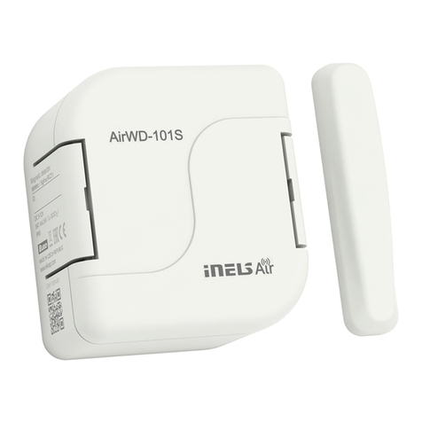
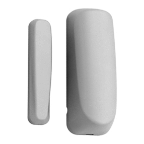
Window / Door detector
EN
Made in Czech Republic
ON
1 2
+
CR2032
Click!
Characteristics /
• The window / door detector is used to detect opening where activation occurs when the mag-
net and the sensor become separated.
• Use:
- in combination with the switching unit for automatic light control (cellar, garage, etc.), or
switching on a GSM gate
- by means of the Smart RF box, detection can be displayed on your smart phone in the form
of a notification; alarms are stored in the history, which is visualized in the application iHC.
• Anti-tamper function: an alarm is triggered if there is an unauthorized interference to detector
(disassembly, power outage...).
• Power supply: battery 3 V / CR2032, the battery life is min. 1 year, … thanks to the ability to turn
off the LED indicator it is possible to extend up to 3 years.
• “Low Battery” Alerts on Your iHC App.
• The detectors are compatible with switching components marked with the iNELS RF Control2
RFIO2communication protocol and the eLAN-RF system components.
• Communication frequency with bidirectional protocol iNELS RF Control2(RFIO2).
Assembly /
12
Push a screwdriver into the
opening at the top of the de-
tector and open the cover.
Push the beaks (mouldings)
at the bottom of the device
down and remove the device
from the base.
3Extrude the mouldings from
the base (e.g. with a screw-
driver).
4Insert the programmed de-
vice into the base and snap
into place with pressure, gen-
tly. Check the correct battery
location.
Replace and snap the front
cover.
56
Place the base at the desired
location (moving window
or door leaf) and fasten with
suitable bonding material *
according to the substrate.
7
1/5
Program the instrument - see
Programming chapter.
Detector /
13
Push a screwdriver into the
opening at the top of the
module and open the cover.
Extrude the mouldings from
the base (e.g. with a screw-
driver).
Place the base at the desired
location (On window or door
frames) and fasten with suit-
able bonding material* ac-
cording to the substrate.
2
Magnetic module /
4Replace and snap the front
cover.
ON
1 2
+
CR2032
ON
1 2
+
CR2032
Click!
Click!
Fenster / Tür Detektor
DE
www.elkoep.com / www.elkoep.de / www.elkoep.at
ELKO EP, s.r.o. | Palackého 493 | 769 01 Holešov, Všetuly | Czech Republic | e-mail: [email protected] | Support: +420 778 427 366
ELKO EP Germany GmbH | Minoritenstr. 7 | 50667 Köln | Deutschland | E-mail: elko@elkoep.de | Tel: +49 (0) 221 222 837 80
ELKO EP Austria GmbH | Laurenzgasse 10/7 | 1050 Wien | Österreich | E-mail: elko@elkoep.at | Tel: +43 (0) 676 942 9314
Eigenschaften
Installation
Drücken Sie den Schrauben-
dreher in die Öffnung im
Oberteil des Detektors und
öffnen Sie die Elementabdec-
kung.
Drücken Sie die Schnäbel
(Formteile) im unteren Teil
des Geräts nach unten und
entfernen Sie das Gerät von
dem Grundgestell.
Brechen Sie die Formteile vom
Grundgestell aus (z. B. mit
Hilfe des Schraubendrehers).
Legen Sie das einprogram-
mierte Gerät in das Grundge-
stell und rasten Sie es unter
leichtem Druck vorsichtig ein.
Überprüfen Sie die korrekte
Position der Batterie.
Befestigen und rasten Sie die
vordere Abdeckung ein.
Programmieren Sie das Gerät
ein - siehe Kapitel Program-
mierung.
Platzieren Sie das Grundgestell
an einer gewünschten Stelle
(beweglicher Fenster- oder
Türflügel) und befestigen Sie
ihn mit einem geeignetem
Verbindungsmaterial * in Ab-
hängigkeit vom Untergrund.
Detektor
Drücken Sie den Schrau-
bendreher in die Öffnung
im Oberteil des Moduls und
öffnen Sie die Elementabdec-
kung.
Brechen Sie die Formteile vom
Grundgestell aus (z. B. mit
Hilfe des Schraubendrehers). Platzieren Sie das Grundge-
stell an einer gewünschten
Stelle (an Fenster- oder
Türrahmen) und befestigen
Sie ihn mit einem geeignetem
Verbindungsmaterial * in Ab-
hängigkeit vom Untergrund.
Befestigen und rasten Sie die
vordere Abdeckung ein.
Magnetischer Modus
• Der Fenster- / Türdetektor dient zur Erkennung des Öffnens, zur Aktivierung kommt es, wenn
der Magnet vom Sensor entfernt wird.
• Gebrauch:
- in Verbindung mit einem Schaltelement zur automatischen Lichtsteuerung (Keller, Garage...)
oder das Schalten des GSM-Gateways,
- Durch intelligente RF-Box kann die Erkennung auf dem Smartphone inForm einer Benachrichtigung
angezeigt werden, die empfangenen Alarme werden in einer Historie gespeichert, die in der iHC-
Anwendung visualisiert wird.
• Antisabotage-Funktion: Bei einem unbefugten Eingriff in denDetektors (Demontage,Unterbrechung
der Stromversorgung...) ertönt der Alarm.
• Stromversorgung: Batterie 3 V / CR2032, Batterielebensdauer min. 1 Jahr, kann durch Ausschalten
der Signalisierungs-LED auf bis zu 3 Jahre verlängert werden.
• Anzeige ausgeladener Batterie mittels der iHC-Anwendung.
• Die Detektoren sind kompatibel mit den Schaltelementen, welche durch Kommunikationsprotokoll
iNELS RF Control2RFIO2und den eLAN-RF Systemelementen bezeichnet sind.
• Kommunikation mit beiderseitigem Protokoll iNELS RF Control2-Protokoll (RFIO2).
02-30/2017 Rev.1
RFWD-100
Window / Door detector
EN
Made in Czech Republic
ON
1 2
• For correct operation of the detector, the correct location position must be maintained so that the
sensing distance is maintained when the window or doors are closed. Therefore, test the position
of the detector and the magnetic modulus before installation.
• The detector is intended for indoor use.
• Before installation, consult with the window or door manufacturer regarding the most suitable
bonding material for where want to place the detector.
• In the appropriate location (at the bottom of the window) you can also use the window in the
ventilation position.
• For 5 minutes after inserting the battery, each connection of the magnet is indicated by the blink-
ing of the red LED.
* countersunk head, screw Ø 3 mm
Assembly recommendations /
60 - 90 % 80 - 95 % 20 - 60 % 0 - 10 % 80- 90 %
brick walls wooden structures
with plaster boards reinforced concrete metal partitions common glass
Radio frequence signal penetration through various construction materials /
☺
☺
☺
☺

☺
RFRP-20
Indications, settings, functions /
Before starting to program, open the detector cover using a screwdriver.
Indicators and adjustment components are located inside the box.
• Red LED - 1x blinks - indicates when the magnet connection is closed / open for 5 minutes after
inserting the battery.
• Red LED - 2x blinks - indicates the case of a weak battery, when the magnetic connection is
either closed / open - if the detector is assigned to a compatible switching component (if the
detector is connected to a (eLAN, RF Touch, iNELS) system, the battery level is indicated in
the system).
TAMPER
Battery holder /
DIP
LED
Magnet /
ON
1 2
• DIP switch setting
DIP1:
OFF - Normal function - magnet open activation.
ON - Inverse function - magnet proximity activation.
DIP2:
OFF - The detector is paired with a compatible component - it does not periodi-
cally send information about the current status
ON - The detector is connected to the system (eLAN, RF Touch, iNELS headquar-
ters) - it sends information in case of a change in status and periodically after
120 minutes.
• Any change to the DIP setting must be saved.
ON
1 2
1
Save the DIP switch settings /
Set the DIP switch (e.g. with a
screwdriver). Insert the battery into the bat-
tery holder in the detector. Be-
ware of the polarity. The red LED
on the detector will blink - set-
ting the DIP switch setting.
2
ON
1 2
+
CR2032
Detector / Magnetic module /
2/5
Fenster / Tür Detektor
DE
www.elkoep.com / www.elkoep.de / www.elkoep.at
ELKO EP, s.r.o. | Palackého 493 | 769 01 Holešov, Všetuly | Czech Republic | e-mail: [email protected]om | Support: +420 778 427 366
ELKO EP Germany GmbH | Minoritenstr. 7 | 50667 Köln | Deutschland | E-mail: [email protected] | Tel: +49 (0) 221 222 837 80
ELKO EP Austria GmbH | Laurenzgasse 10/7 | 1050 Wien | Österreich | E-mail: elko@elkoep.at | Tel: +43 (0) 676 942 9314
Detektor Magnetischer Modus
Batteriehalter
Magnet
Ziegelwände Holzkonstruktionen
mit
Gipskartonplatten
Stahlbeton Metallwände Glas
Radiofrequenzsignal dringt durch verschiedene Baumaterialien
Anzeige, Einstellungen, Funktionen
• Für die korrekte Funktion des Detektors muss die korrekte Positionierung so eingehalten werden,
damit bei geschlossenem Fenster/Tür der Aufnahme-Abstand eingehalten ist. Testen Sie vor der
Installation die Lagen der Positionierung des Detektors und des Magnetmoduls.
• Der Detektor ist für den Gebrauch im Innenbereich vorgesehen.
• Wenden Sie sich vor der Installation des Sensors an den Hersteller des Fensters (Tür), an das Sie
den Detektor platzieren möchten.
• Bei geeigneter Platzierung (im unteren Teil des Fensters) kann der Detektor auch am Fenster in der
Lüftungsposition verwendet werden.
• 5 Minuten nach dem Einlegen der Batterie wird jede Näherung und Entfernung des Magnets mit
kurzes Blinken der roten LED angezeigt.
* Senkholzschraube, Holzschraubendurchschnitt 3 mm
Empfehlung für die Montage
Vor Beginn der Programmierung ist die Detektorabdeckung mit einem Schraubenzieher zu öffnen.
Anzeigen und Einstellungen befinden sich innerhalb der Box.
• Die rote LED - blinkt 1x - 5 Minuten nach dem Einlegen der Batterie wird jede Näherung und
Entfernung angezeigt.
• Rote LED - blinkt 2x bei der Näherung / Entfernung des Magnets bei schwacher Batterie -
wenn der Detektor an das kompatible Schaltelement angeschlossen ist (ist der Detektor an
das System (eLAN, RF Touch, iNELS-Zentrale), wird die schwache Batterie im System angezeigt).
• Einstellung des DIP-Umschalters
DIP1:
OFF - normale Funktion - Aktivierung bei dem Entfernen des Magnets.
ON - inverse Funktion - Aktivierung bei der Magnetnäherung.
DIP2:
OFF - der Detektor ist mit einem kompatiblen Element gepaart - es sendet nicht
regelmäßig Informationen über den aktuellen Zustand
ON - der Melder ist an das System angeschlossen (eLAN, RF Touch, iNELS Zentrale)
- sendet bei der Änderung des Zustandes sowie periodisch nach 120 Minuten
eine Information.
• Jede Änderung der DIP-Einstellung muss gespeichert werden.
Einstellung des DIP-Schalters
(z. B. mit einem Schrauben-
zieher).
Legen Sie die Batterie in den
Batteriehalter im Detektor ein.
Achten Sie auf die Polarität. Die
rote LED am Detektor blinkt -
damit wird die Einstellung des
DIP-Schalters eingestellt.
Speicherung der Einstellung des DIP-Umschalters
02-30/2017 Rev.1
RFWD-100
Window / Door detector
EN
Made in Czech Republic
Compatibility /
• control units
eLAN-RF-003, eLAN-RF-Wi-003
• switches
RFSA-61B, RFSA-62B, RFSAI-61B, RFSA-61M, RFSA-66M, RFSC-61, RFUS-61
• The detector can only be assigned to components marked with the iNELS RF
Control2RFIO2communication protocol.
13
PROG > 1s
1 x PROG < 1s
1 x
Functions and programming with compatible switches /
Function ON/OFF /
Description of ON/OFF /
The output contact of the switching component switches on when the detector activates, and
switches off when deactivated.
Programming /
Press of programming button
on compatible actuator for
1 second will activate actua-
tor into programming mode.
LED is flashing in 1s interval.
Slide the battery into the bat-
tery holder in the detector. Be-
ware of the polarity. The red LED
on the detector will blink. The
LED on a compatible compo-
nent will blink at a faster interval
- thereby assigning the detector
to the component.
Press of programming but-
ton on compatible actuator
shorter then 1 second will fin-
ish programming mode, LED
switches off.
2
ON
1 2
+
CR2032
ON
1 2
+
CR2032
ON
1 2
+
CR2032
31
PROG > 1s
1 x
Function "delayed return with time setting" /
Description of the delayed return function with time setting /
The output contact of the switching component switches on when the detector activates, it
opens after the set time interval has elapsed.
Programming /
Press of programming button
on compatible actuator for
1 second will activate actua-
tor into programming mode.
LED is flashing in 1s interval.
Slide the battery into the bat-
tery holder in the detector.
Beware of the polarity. The
red LED on the detector will
blink. The LED on a compat-
ible component will blink at
a faster interval - thereby as-
signing the detector to the
component.
Remove the battery from the
detector and reinsert it after
30 seconds. The red LED on
the detector will blink. The
LED on a compatible com-
ponent will flash at a faster
interval.
2
30 s
t = 2s . . . 60min

54 Remove the battery from the detector again. After
30 seconds, press the programming button for more than
5 seconds to bring the compatible component into timer
mode. LED 2x blinks at second intervals. When the button is
released, delayed return time is retrieved.
After setting the desired time (within 2s ...
60min), the timer mode ends by inserting the
battery into the detector. The red LED on the
detector will blink. This saves the time interval
stored in the memory of the component, the
LED on the compatible component blinks.
PROG > 5s
1 x
30 s
ON
1 2
+
CR2032
ON
1 2
+
CR2032
3/5
Fenster / Tür Detektor
DE
www.elkoep.com / www.elkoep.de / www.elkoep.at
ELKO EP, s.r.o. | Palackého 493 | 769 01 Holešov, Všetuly | Czech Republic | e-mail: [email protected]om | Support: +420 778 427 366
ELKO EP Germany GmbH | Minoritenstr. 7 | 50667 Köln | Deutschland | E-mail: [email protected] | Tel: +49 (0) 221 222 837 80
ELKO EP Austria GmbH | Laurenzgasse 10/7 | 1050 Wien | Österreich | E-mail: elko@elkoep.at | Tel: +43 (0) 676 942 9314
Kompatibilität
• Bedienungselemente
eLAN-RF-003, eLAN-RF-Wi-003
• Schaltaktoren
RFSA-61B, RFSA-62B, RFSAI-61B, RFSA-61M, RFSA-66M, RFSC-61, RFUS-61
• Der Detektor kann nur den durch das Kommunikationsprotokoll iNELS RF
Control2(RFIO2) gekennzeichneten Elementen zugeordnet werden.
Durch ein 1 Sekunde langes
Drücken der Programmiertaste
auf dem kompatiblen Element
wird das Element in den
Programmiermodus versetzt.
LED blinkt im 1s-Intervall.
Legen Sie die Batterie in den
Batteriehalter im Detektor
ein. Achten Sie auf die Pola-
rität. Die rote LED am Detek-
tor blinkt. Die LED auf dem
kompatiblen Element blinkt
in einem schnelleren Intervall
- hiermit wird der Detektor
dem Element zugeordnet.
Entfernen Sie die Batterie
aus dem Detektor und legen
Sie diese nach 30 Sekunden
wieder ein. Die rote LED am
Detektor blinkt. Die LED auf
dem kompatiblen Element
blinkt in einem schnelleren
Intervall.
Entfernen Sie die Batterie noch einmal aus dem Detektor.
Drücken Sie nach 30 Sekunden die Programmiertaste für
eine Zeit länger als 5 Sekunden, womit das kompatible
Element in den Timermodus gebracht wird.
Die LED blinkt 2x in Sekunden-Intervallen. Wird die Taste
losgelassen, wird die verzögerte Rückkehrzeit eingelesen.
Nach dem Timing der benötigten Zeit
(innerhalb von 2s ... 60 Minuten), der Timer-
Modus endet mit dem Einlegen der Batterie in
den Detektor. Die rote LED am Detektor blinkt
kurz einmal. Dadurch wird das eingestellte
Zeitintervall im Speicher des Elements
gespeichert, die LED am kompatiblen Element
blinkt.
Funktion„Zeitverzögerte Rückkehr mit der Zeiteinstellung"
Beschreibung der Funktion zeitverzögerter Rückkehr mit der Zeiteinstellung
Der Ausgangskontakt des Schaltelements schaltet bei der Aktivierung ein und löst nach dem
Ablauf des Zeitintervalls aus.
Programmierung
Funktionen und Programmierung mit kompatiblen Schaltern
Funktion ON/OFF
Der Ausgangskontakt des Schaltelements schaltet bei der Aktivierung ein. Bei Deaktivierung
entsperrt.
Durch ein 1 Sekunde langes
Drückender Programmiertaste
auf dem kompatiblen Element
wird das Element in den
Programmiermodus versetzt.
LED blinkt im 1s-Intervall.
Legen Sie die Batterie in den
Batteriehalter im Detektor ein.
Achten Sie auf die Polarität. Die
rote LED am Detektor blinkt.
Die LED auf dem kompatiblen
Element blinkt in einem
schnelleren Intervall - hiermit
wird der Detektor dem Element
zugeordnet.
Drücken der Programmier-
taste auf dem kompatiblen
Element, kürzer als 1 Sekunde,
der Programmiermodus wird
beendet. LED leuchtet nicht
mehr.
Beschreibung der Funktion ON/OFF
Programmierung
02-30/2017 Rev.1
RFWD-100
Window / Door detector
EN
Made in Czech Republic
Detector communication through a repeater /
12
When inserting the RFRP-20
into an electrical socket (upon
power-up), the programming
button must be pressed. The
green LED flashes. Then when
the red LED button illumi-
nates, release the button.
By one short press of the
programming button on the
RFRP-20, you move to the
position for input into the ad-
ditional learning mode. The
red LED flashes - after 5s the
RFRP-20 enters the additional
learning mode. The LED stops
flashing.

PROG < 1s
1 x

End learning mode by a short
press of the programming
button on the RFRP-20. By do-
ing so, the programmed de-
tector address is stored in the
memory. The red LED will flash
for 1 second, then the green
LED will remain illuminated.
4
PROG <1s
1 x

Insert the battery into the
battery holder in the detector
(Beware of the polarity, the
red LED on the detector will
blink). A flashing green LED on
the RFRP-20 indicates that the
RFWD-100 has been recorded
in the RFRP-20 memory.
3
Programming with the RF control units /
address /
For programming and communicating the detector with the system
components, the address shown on the underside of the detector or
at the bottom of the open device is used.
4/5
xxxxxx
ON
1 2
+
CR2032
xxxxxx
ON
1 2
+
CR2032
6
PROG < 1s
1 x
Press of programming but-
ton on compatible actuator
shorter then 1 second will fin-
ish programming mode, LED
switches off.
RFRP-20
You can set repeat functions for all components marked with iNELS RF Control2(RFIO2) using
the RFAF/USB service key.
RFAF/USB
Fenster / Tür Detektor
DE
www.elkoep.com / www.elkoep.de / www.elkoep.at
ELKO EP, s.r.o. | Palackého 493 | 769 01 Holešov, Všetuly | Czech Republic | e-mail: [email protected]om | Support: +420 778 427 366
ELKO EP Germany GmbH | Minoritenstr. 7 | 50667 Köln | Deutschland | E-mail: [email protected] | Tel: +49 (0) 221 222 837 80
ELKO EP Austria GmbH | Laurenzgasse 10/7 | 1050 Wien | Österreich | E-mail: elko@elkoep.at | Tel: +43 (0) 676 942 9314
Drücken der Programmier-
taste auf dem kompatiblen
Element, kürzer als 1 Sekunde,
der Programmiermodus wird
beendet. LED leuchtet nicht
mehr.
Programmieren mit RF-Steuereinheiten
Für die Programmierung und Kommunikation des Detektors mit
Systemelementen dient die Adresse auf der Unterseite des Detektors
oder im unteren Teil des geöffneten Geräts.
Beim Drücken des RFRP-20
in eine Steckdose (Netzteil)
muss die Programmiertaste
gedrückt werden. Die grüne
LED blinkt. Lassen Sie die
Taste los, nachdem die rote
LED aufleuchtet.
Durch ein kurzes Drücken der
Programmiertaste auf RFRP-20
kommen Sie auf die Position
für den Einstieg in den Einlern-
Modus über. Rote LED blinkt
- Nach 5s geht RFRP-20 in den
Einlern-Modus über. Die LED
hört auf zu blinken.
Durch ein kurzes Drücken
der Programmiertaste auf
RFRP-20 beenden Sie den
Einlern-Modus. Damit wird
die programmierte Adresse
des Detektors im Speicher
gespeichert. Die rote LED
blinkt einmal 1s lang und
danach leuchtet permanent
die grüne LED leuchtet auf.
Legen Sie die Batterie in den
Batteriehalter im Detektor ein.
(Achten Sie auf die Polarität. Die
rote LED am Detektor blinkt.)
Damit wird das Senden des
Signals durchgeführt. Ein kurzes
Blinken grüner LED auf der
RFRP-20-Einheit zeigt an, dass
der Detektor in den RFRP-20-
Speicher eingetragen wurde.
Sie können die Repeater-Funktion für alle mit dem Logo iNELS RF Control2(RFIO2) markierten
Elementen mittels RFAF/USB-Serviceschlüssel einstellen.
Detektor-Kommunikation über den Repeater
Adresse
02-30/2017 Rev.1
RFWD-100
Window / Door detector
EN
Made in Czech Republic
Warning
Instruction manual is designated for mounting and also for user of the device. It is always a part of its packing. Instal-
lation and connection can be carried out only by a person with adequate professional qualification upon under-
standing this instruction manual and functions of the device, and while observing all valid regulations.Trouble-free
function of the device also depends on transportation, storing and handling. In case you notice any sign of damage,
deformation, malfunction or missing part, do not install this device and return it to its seller. It is necessary to treat
this product and its parts as electronic waste after its lifetime is terminated. Before starting installation, make sure
that all wires, connected parts or terminals are de-energized. While mounting and servicing observe safety regula-
tions, norms, directives and professional, and export regulations for working with electrical devices. Do not touch
parts of the device that are energized – life threat. Due to transmissivity of RF signal, observe correct location of
RF components in a building where the installation is taking place. RF Control is designated only for mounting in
interiors. Devices are not designated for installation into exteriors and humid spaces. The must not be installed into
metal switchboards and into plastic switchboards with metal door – transmissivity of RF signal is then impossible.
RF Control is not recommended for pulleys etc. – radiofrequency signal can be shielded by an obstruction, inter-
fered, battery of the transceiver can get flat etc. and thus disable remote control.
Technical parameters /
Attention:
When you instal iNELS RF Control system, you have to keep minimal distance 1 cm between each units.
Between the individual commands must be an interval of at least 1s.
5/5
Power supply:
Drained battery indicator:
Transmission frequency:
Communication protocol:
Working temperature:
Protection:
Color:
Dimension:
Weight:
1
Replacement of a battery /
2
Push a screwdriver into the
opening at the top of the de-
tector and open the cover.
Remove the original battery
and insert a new battery into
the battery holder. Beware of
the polarity. The red LED on
the detector will blink.
Replace and snap the front
cover.
3
When handling a device unboxed it is important to avoid contact with liquids. Never place
the device on the conductive pads or objects, avoid unnecessary contact with the compo-
nents of the device.
Safe handling /
ON
1 2
+
CR2032
ON
1 2
+
CR2032
Click!
Fenster / Tür Detektor
DE
www.elkoep.com / www.elkoep.de / www.elkoep.at
ELKO EP, s.r.o. | Palackého 493 | 769 01 Holešov, Všetuly | Czech Republic | e-mail: [email protected]om | Support: +420 778 427 366
ELKO EP Germany GmbH | Minoritenstr. 7 | 50667 Köln | Deutschland | E-mail: [email protected] | Tel: +49 (0) 221 222 837 80
ELKO EP Austria GmbH | Laurenzgasse 10/7 | 1050 Wien | Österreich | E-mail: elko@elkoep.at | Tel: +43 (0) 676 942 9314
Die Betriebsanleitung dient der Montage, sowie dem Benutzer des Geräts. Sie ist immer im Lieferumfang enthalten.
Die Montage und der Anschluss darf nur durch eine Person mit einer angemessenen Berufsqualifikation, nach dieser
Bedienungsanleitung und Funktionen des Gerätes und unter Beachtung aller gültigen Vorschriften ausgeführt
werden. Die störungsfreie Funktion des Gerätes hängt auch von Transport, Lagerung und Handhabung ab. Falls Sie
irgendwelche Anzeichen von Beschädigung, Verformung, Fehlfunktionen oder Fehlteilen feststellen, ie das Gerät
nicht und wenden sich an den Verkäufer. Es ist notwendig, dieses Produkt und Teile davon als Elektronikschrott zu
behandeln, nachdem seine Lebensdauer beendet ist.Vor Beginn der Montage ist sicherzustellen, dass alle Leitungen,
miteinander verbundenen Teilen oder Anschlüsse spannungsfrei sind. Während der Montage und der Wartung
sind die Sicherheitsvorschriften, Normen, Richtlinien für die Arbeit mit elektrischen Geräten zu beachten. Berühren
Sie keine Teile des Gerätes, die mit Energie versorgt werden - Lebensgefahr. Aufgrund der Sendeleistung des RF-
Signals, beachten Sie den geeigneten Montageort der RF-Komponenten in einem Gebäude, in dem die Installation
stattfindet. RF Control ist nur für die Montage im Innenbereich geeignet. Geräte sind nicht für die Montage in
Außenbereichen und Feuchträumen geeignet. RF Control Komponenten dürfen nicht in Metallschalttafeln und in
Kunststoff -Schalttafeln mit Metalltür installiert werden - Die Durchlässigkeit des RF-Signals ist dann nicht gegeben.
RF Control ist nicht für Aufzüge geeignet - das RF Signal kann gestört und abgeschirmt werden, die Batterie des
Emfängers verliert schnell die Leistung etc. - dieses verhindert die Steuerung durch eine Steuerungseinheit.
Warnung
Technische Parameter
Achtung:
Bei der Installation Aktoren iNELS RF Control muss es der Mindestabstand 1 cm geachtet sein.
Zwischen aufeinanderfolgenden Befehlseingaben sollte mindesten 1 s Abstand liegen.
Beim Umgang mit diesem Gerät, ist es wichtig, den Kontakt mit Flüssigkeiten zu vermeiden.
Stellen Sie das Gerät nie auf leitende Flächen oder Objekte und vermeiden Sie unnötigen
Kontakt mit den Komponenten des Geräts.
Sicherer Umgang
Versorgung:
Anzeige ausgeladener Batterie:
Sendefrequenz:
Kommunikationsprotokoll:
Arbeitstemperatur:
Schutzart:
Farbe:
Abmessung:
Gewicht:
baterry / Batterie 1x 3 V CR2032
yes / ja
866 MHz, 868 MHz, 916 MHz
iNELS RF Control2(RFIO2)
-10.. +50°C
IP20
white / weiß
25 x 75 x 16 mm / 15 x 75 x 14 mm
16 g / 13 g
Drücken Sie den Schrauben-
dreher in die Öffnung im
Oberteil des Detektors und
öffnen Sie die Elementabdec-
kung.
Entfernen Sie die alte Batterie
und legen Sie eine neue
Batterie in den Batteriehalter
ein. Achten Sie auf die Polarität.
Die rote LED am Detektor
blinkt.
Befestigen und rasten Sie die
vordere Abdeckung ein.
Ersatz einer Batterie

This manual suits for next models

2

Other Elko Security Sensor manuals

Elko iNELS RFSF-1B User manual

Elko

Elko iNELS RFSF-1B User manual

Elko inelsAir AirSF-100S User manual

Elko

Elko inelsAir AirSF-100S User manual

Elko iNELS RFSF-100 User manual

Elko

Elko iNELS RFSF-100 User manual

Elko AirMD-100L User manual

Elko

Elko AirMD-100L User manual

Elko inels RFSF-1B User manual

Elko

Elko inels RFSF-1B User manual

Elko iNELS Air AirWD-100NB User manual

Elko

Elko iNELS Air AirWD-100NB User manual

Elko iNels Air AirWD-101 Series User manual

Elko

Elko iNels Air AirWD-101 Series User manual

Elko iNels DMD3-1 User manual

Elko

Elko iNels DMD3-1 User manual

Elko iNELS RFWD-100 User manual

Elko

Elko iNELS RFWD-100 User manual

Elko iNELS RFWD-100 User manual

Elko

Elko iNELS RFWD-100 User manual

Elko iNels RFMD-100 User manual

Elko

Elko iNels RFMD-100 User manual

Elko INELS RFWD-100 User manual

Elko

Elko INELS RFWD-100 User manual

Elko iNels DMD3-1 User manual

Elko

Elko iNels DMD3-1 User manual

Elko iNELS RFMD-100 User manual

Elko

Elko iNELS RFMD-100 User manual

Elko inels RFSF-1B User manual

Elko

Elko inels RFSF-1B User manual

Elko ineLS RFSF-100 User manual

Elko

Elko ineLS RFSF-100 User manual

Elko iNELS RFSF-100 User manual

Elko

Elko iNELS RFSF-100 User manual

Elko inels RFWD-100 User manual

Elko

Elko inels RFWD-100 User manual

Elko Inels RFSF-18 User manual

Elko

Elko Inels RFSF-18 User manual

Elko inelsAir AirSF-100L User manual

Elko

Elko inelsAir AirSF-100L User manual

Elko inels RFSF-1B User manual

Elko

Elko inels RFSF-1B User manual

Elko iNels Air AirSF-100 User manual

Elko

Elko iNels Air AirSF-100 User manual

Elko iNELS Air AirSF-100NB Instruction manual

Elko

Elko iNELS Air AirSF-100NB Instruction manual

Elko iNELS RFSF-100 Operator's manual

Elko

Elko iNELS RFSF-100 Operator's manual

Popular Security Sensor manuals by other brands

3M SecureFit X5500NVE instructions

3M

3M SecureFit X5500NVE instructions

Protector WA-5 operating instructions

Protector

Protector WA-5 operating instructions

AVE domina AF976R-DB quick start guide

AVE

AVE domina AF976R-DB quick start guide

Stahl YL4IS Series operating instructions

Stahl

Stahl YL4IS Series operating instructions

Protekt P-90 instruction manual

Protekt

Protekt P-90 instruction manual

Escort MAX 3 quick start guide

Escort

Escort MAX 3 quick start guide

Rotech SafePass RD6 user manual

Rotech

Rotech SafePass RD6 user manual

Carrier ARITECH VE1012PI Installation sheet

Carrier

Carrier ARITECH VE1012PI Installation sheet

jablotron JA-115P quick start guide

jablotron

jablotron JA-115P quick start guide

ITALIANA SENSORI 8137-ISR079 Installation, operation and maintenance manual

ITALIANA SENSORI

ITALIANA SENSORI 8137-ISR079 Installation, operation and maintenance manual

Balluff BTL7-C/E509-M Series user guide

Balluff

Balluff BTL7-C/E509-M Series user guide

Visonic SD-304C PG2 installation instructions

Visonic

Visonic SD-304C PG2 installation instructions

Skil 0550 instructions

Skil

Skil 0550 instructions

S&S Merlin 1500S user guide

S&S

S&S Merlin 1500S user guide

Velleman CS100N user manual

Velleman

Velleman CS100N user manual

Orno OR-CR-205 manual

Orno

Orno OR-CR-205 manual

Viking PB-1 product manual

Viking

Viking PB-1 product manual

S-Tech STCP-1000 owner's manual

S-Tech

S-Tech STCP-1000 owner's manual

manuals.online logo
manuals.online logoBrands
  • About & Mission
  • Contact us
  • Privacy Policy
  • Terms and Conditions

Copyright 2025 Manuals.Online. All Rights Reserved.