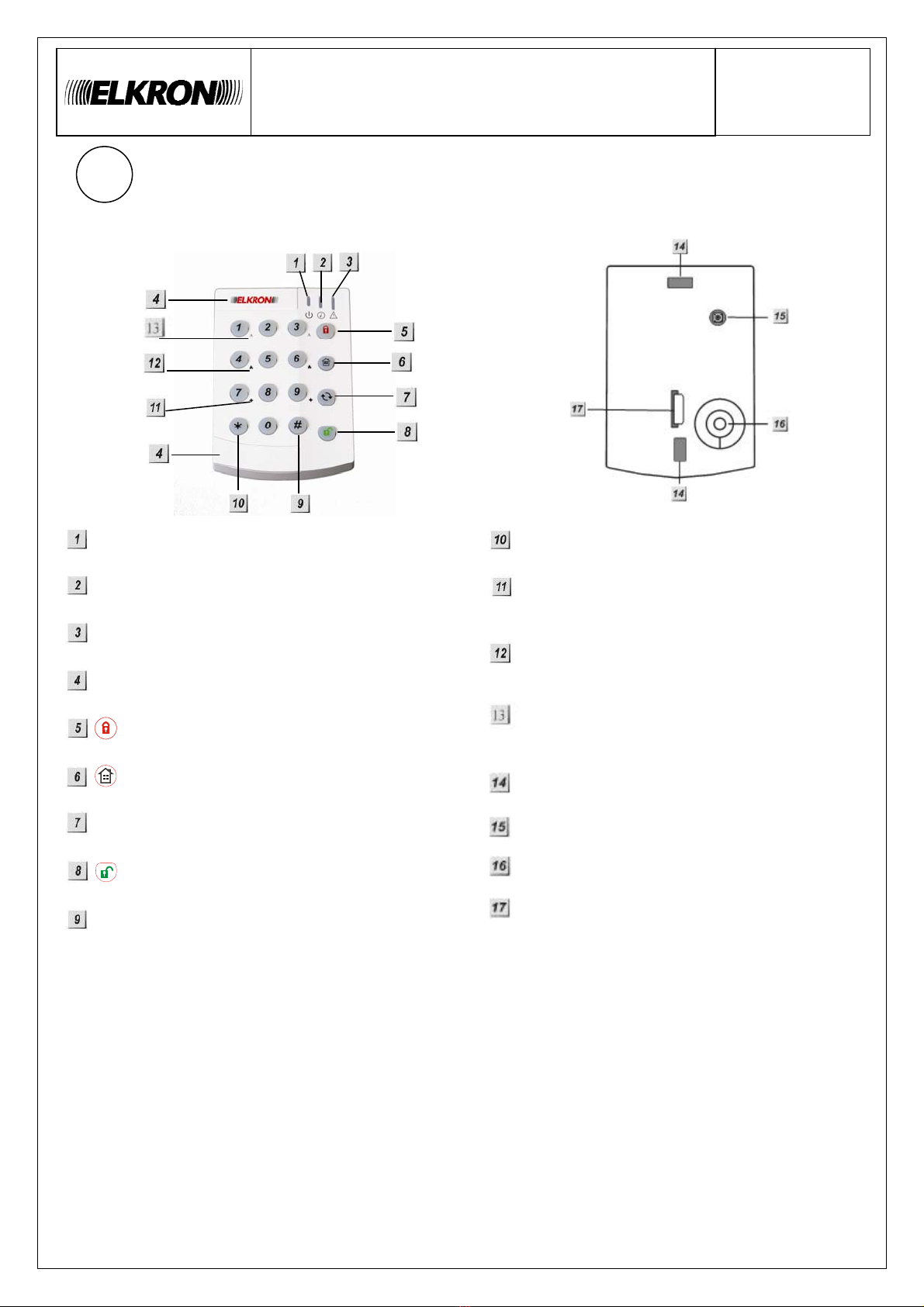
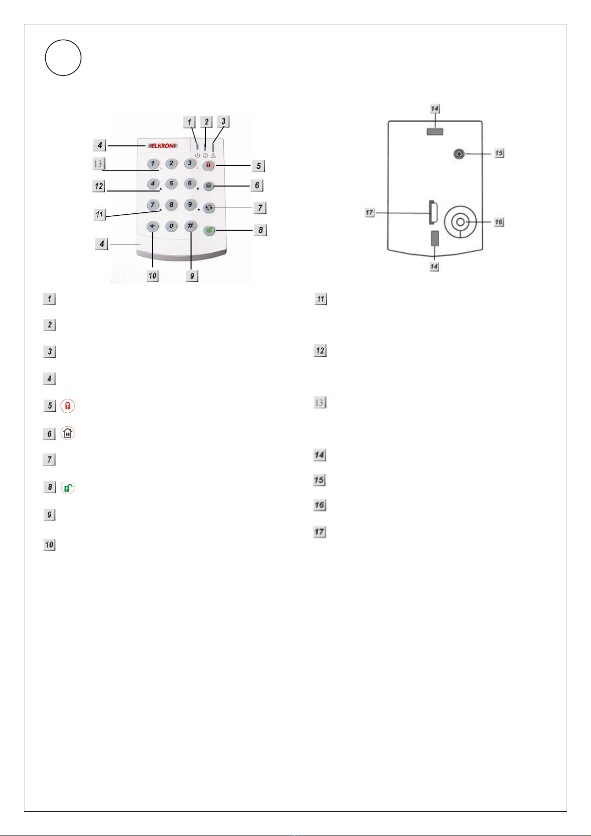
Elkron KP200 User manual

1/12
IDENTIFYING THE PARTS
Green Active LED
Red TX LED
Orange Fault LED
Slide Out Section
Arm Key
Home Key
Key
Disarm Key
#Key
¿Key
+ Key
press both 7 and 9 to trigger emergency alarm
Fire Key
press both 4 and 6 to trigger fire alarm
A Key
press both 1 and 3 to trigger panic alarm
Mounting Hole
Tamper Switch
Buzzer
Battery Insulator
LED INDICATOR
•Green Active LED
oGreen Active LED on: the system is in Normal Operation Mode.
oGreen Active LED flash: the system is in Test Mode.
oWhen the Keypad is idle, all LEDs are off. After any key press, the Green Active LED
turns on for 5 seconds indicating that Keypad is active.
oThe Green Active LED will turn off after successful completion of a valid keystroke
sequence or when the pause in between key stokes is longer than 5 seconds.
oWhen the Green Active LED turns off before a valid keystroke sequence is completed
(5 seconds), the previous entered keys are ignored.
•Red TX LED
oThe Red TX LED flashes 2 times: the signal is transmitted.
GB
REMOTE KEYPAD (KP200)
C
CL
LA
AV
VI
IE
ER
R
D
DI
IS
ST
TA
AN
NT
T (KP200)
F
FE
ER
RN
NT
T
A
AS
ST
T
A
AT
TU
UR
R (KP200)
DS80KP82-001A
LBT80627

2/12
•Orange Fault LED
oOrange Fault LED flashes for 5 times: Battery is low during operation.
oOrange Fault LED on: Tamper is trigger during operation.
oWhen Keypad Tamper is trigger and battery is low, the Orange Fault LED turns on
during operation.
Note:
¾A short beep will be sounded with each key press, which confirms valid pressing.
¾4 continuous beeps will sound indicating the user that he has entered invalid keystroke, and the
user is asked to repeat the process again.
POWER
•The Keypad uses a CR2450 3V 540mAH lithium battery as its power source. It has a typical
battery life of over 7 years at an average of 4 activations a day.
•The Keypad can also detect the battery status. Low battery detection operates where the Keypad
has enough reserve energy to typically operate for 4 month before complete exhaustion.
•When the Keypad has low battery, the Orange Fault LED will flash during operation and a low
battery signal will be transmitted along with regular signal transmissions.
•Before shipment, the battery is pre-installed by the factory.
TAMPER PROTECTION
•Keypad is protected against any attempt to open the lid or to detach Keypad from its mounting
surface.
•Tamper protection is disabled when in Test Mode.
•When Keypad Tamper is trigger, it will send KP Tamper Fault signal to Control Panel and the
Orange Fault LED will turn on. In addition, during using the keypad, Orange Fault LED will stay
on to indicate the KP Tamper Fault.
POWER SAVING FEATURE
•When the Keypad is not being used, no power is consumed. Whenever a key is pressed, the
Keypad will activate and “wake-up” for 5 seconds when any key is pressed.
•After 5 seconds of key inactivity, the power turns off again and returns to Stand-by mode.
•Upon completion of a command input, the power turns off and returns to Stand-by mode.
TEST MODE
•Keypad can be put into Test mode by entering the PIN code (default: 0000) followed by *.
The Green Active LED will flash and Keypad sounds a long beep.
•To exit Test mode, press twice, Keypad will sound a long beep and the Green Active LED
will turn on, then Keypad returns to Normal Operation mode.
Note:
¾Test Mode is helpful to bypass Keypad Tamper alarm when installing, replacing low batteries or
removing to different mount site.
¾When Keypad is in Test mode, it operates as wake-up condition thus will NOT disconnect after 5
seconds.
¾In Test Mode, if no key is pressed within 30 minutes, the Keypad will automatically exit Test
Mode to Normal Operation mode.
The Keypad Test mode enables the following functions:
Transmit Keypad learn signal — press * and then 1
Dual-key Panic Alarm Enable — press *and then 2
Dual-key Fire Alarm Enable — press *and then 3
Dual-key Medical Alarm Enable — press *and then 4

3/12
Change the Pin Code — press *and then 6
oEnter Old Pin Code and then press
oEnter New 4-digit Pin Code and then press #
Dual Key Disable — Press *and then 5
Quit Test Mode —press twice.
Arm/ Home without PIN Code — press * and then 8
Arm/ Home with PIN Code — press *and then 9
Note:
¾For wrong entering or operating the Keypad will sound 4 short beeps.
¾When the Pin Code is wrong entered for 4 times, the Keypad will sound 4 beeps and all LED
flash 4 times. The Keypad will be locked for 1 min. After 1 minute, the Keypad will sound one
beep and can be used again.
INSTALLATION PROCEDURES
Step 1. Put Keypad in Test mode by entering “0000” (default PIN code), then press *. Keypad will
sound 1 long beep and the Green Active LED will steadily flash.
Step 2. Adding Keypad into the Control Panel:
1. Put the Control panel into Device +/- menu and select the Add Devices sub menu.
2. Press *and then 1when requested. Keypad and Control Panel will beep once.
3. Refer to the operation manual of your control Panel under the section of Device +/- to
complete the learn-in process.
Step 3. After the Keypad is learnt-in, put the Control Panel into Walk Test mode, hold the Keypad in
the desired location, press the *then 1button to confirm this location is within signal range of
the Control Panel.
Step 4. When you are satisfied that the Keypad works in the chosen location, you can proceed with
mounting the Keypad following the steps described below (see Mounting Keypad).
Step 5. Setting the Pin Code:
1. Press *then 6, a long beep will be sound.
2. Enter 0000 (default PIN code)
3. Press , Keypad sounds a long beep.
4. Enter your new 4-digit code.
5. Press #, Keypad sounds a long beep
Step 6. Press twice to exit Test mode and the installation is completed.
MOUNTING THE KEYPAD
To mount the Keypad:
1. Remove the 2 slide-out sections of front cover.
2. Using the 2 mounting holes as a template, mark off the positions in the most appropriate place.
3. Insert the wall plugs if fixing into plaster or brick surface.
4. Screw the Keypad onto the wall plugs.
5. Replace the 2 slide-out sections.
HOW TO SET SYSTEM MODE
Arm/Home with Pin Code
¾Arm Mode: Enter anyone of Control Panel user codes and press key. Red TX LED will flash
5 times and the Keypad sounds a long beep.
¾Home Mode: Enter anyone of Control Panel user codes and press key. Red TX LED will
flash 5 times and the Keypad sounds 3 beeps.
¾Disarm Mode: Enter anyone of Control Panel user codes and press key. Red TX LED will
flash 5 times and the Keypad sounds 2 beeps.
¾Enter Test Mode — Enter Keypad PIN code and press * key. The Keypad will sound 1 long
beep and Green Active LED flashes steadily.

4/12
¾Panic Alarm — Press 1+ 3simultaneously at the same time. Red TX LED will flash 5 times and
the Keypad sounds a long beep.
¾Fire Alarm — Press 4+ 6simultaneously at the same time. Red TX LED will flash 5 times and
the Keypad sounds a long beep.
¾Medical Alarm — Press 7+ 9simultaneously at the same time. Red TX LED will flash 5 times
and the Keypad sounds a long beep.
¾For wrong entering or operating the Keypad will sound 4 short beeps.
Arm/ Home without PIN Code
¾Arm Mode: Press key. Red TX LED will flash 5 times and the Keypad sounds a long beep.
¾Home Mode: Press key. Red TX LED will flash 5 times and the Keypad sounds 3 beeps.
¾Disarm Mode: Enter anyone of Control Panel user codes and Key. Red TX LED will flash 5
times and the Keypad sounds 2 beeps.
¾Enter Test Mode — Enter Keypad PIN code and press * key. The Keypad will sound 1 long
beep and Green Active LED flashes steadily.
¾Panic Alarm — Press 1+ 3simultaneously at the same time. Red TX LED will flash 5 times and
the Keypad sounds a long beep.
¾Fire Alarm — Press 4+ 6simultaneously at the same time. Red TX LED will flash 5 times and the
Keypad sounds a long beep.
¾Medical Alarm — Press 7 + 9 simultaneously at the same time. Red TX LED will flash 5 times
and the Keypad sounds a long beep.
¾For wrong entering or operating the Keypad will sound 4 short beeps.
CHANGE OF BATTERY
1. Put the Control Panel to programming menu.
2. Dismount the Keypad by first removing the slide-out sections then the mounting screws.
3. Open the Keypad by loosening the 2 fixing screw located behind the Keypad.
4. Take out the old battery and wait for 5 minutes before replacing the new battery in the battery
compartment, with unmarked (negative) side of battery facing down.
5. Close the case using the rear fixing screws.
6. Screw back the Keypad to the surface with mounting screws, and then re-insert the slide-outs.
7. Put the Control Panel to exit Programming Menu.
APPENDIX
If you have forgotten the Pin Code or anything wrong happened in the Keypad, you can reset the
Keypad to factory default and reinitialize it.
Reset to factory default:
Step 1 Remove one of the batteries and release the tamper.
Step 2 Press 3while inserting the removed battery back in.
Step 3 Continue pressing 3until 3 short beeps to indicate successful reset.
Step 4 Release 3.
Note:
After reset, PIN code reverts to factory default values, “0000”. Keypad will need a new learn-in process
to start functioning.

5/12
IDENTIFICATION DES PIÈCES
Voyant actif vert
Voyant TX rouge
Voyant d'erreur orange
Section coulissante
Touche d'armement
Touche Domicile
Touche
Touche de désarmement
Touche #
Touche ¿
Touche +
Appuyez simultanément sur 7 et 9 pour
déclencher l'alarme d'urgence
Touche Incendie
Appuyez simultanément sur 4 et 6 pour
déclencher l'alarme d'incendie
Touche A
Appuyez simultanément sur 1 et 3 pour
déclencher l'alarme d'urgence
Orifices de montage
Commutateur anti-sabotage
Signal sonore
Isolateur de pile
VOYANT LUMINEUX
•Voyant actif vert
oVoyant actif vert allumé : le système est en mode de fonctionnement normal.
oVoyant actif vert clignotant : le système est en mode de test.
oLorsque le clavier est inactif, les voyants sont éteints. Si l'une des touches est enfoncée,
le voyant actif vert s'allume pendant 5 secondes pour indiquer que le clavier est actif.
oLe voyant actif vert s'éteint après une suite de touches valable ou lorsque la pause entre
les pressions sur les touches est supérieure à 5 secondes.
oLorsque le voyant actif vert s'éteint avant qu'une suite de touches valable soit terminée (5
secondes), les touches saisies préalablement sont ignorées.
•Voyant TX rouge
oLe voyant TX rouge clignote 2 fois : le signal est transmis.
F

6/12
•Voyant d'erreur orange
oLe voyant d'erreur orange clignote 5 fois : La pile est faible lors du fonctionnement.
oVoyant d'erreur orange allumé : le sabotage est déclenché pendant le fonctionnement.
oLorsque le sabotage du clavier est déclenché et que la pile est faible, le voyant d'erreur
orange s'allume pendant le fonctionnement.
Remarque:
¾Un bip court est émis à chaque pression sur une touche, confirmant la validité de l'action.
¾Quatre bips continus retentissent pour indiquer que la touche saisie est invalide, et inviter à
recommencer le processus.
ALIMENTATION
•Le clavier utilise une pile lithium CR2450 de type 50 mAh comme source d'alimentation.
L'autonomie normale de la pile est supérieure à 7 ans avec une moyenne de 4 activations par
jour.
•Le clavier peut également détecter l'état de la pile. La détection de pile faible se déclenche
généralement lorsque le PIR peut encore fonctionner pendant quatre mois avant épuisement
complet.
•Lorsque la pile du clavier est faible, le voyant d'erreur orange clignote pendant le
fonctionnement et un signal de pile faible est transmis en même temps que les transmissions
normales.
•La pile est préinstallée en usine avant expédition.
PROTECTION ANTI-SABOTAGE
•Le clavier est protégé contre toute tentative d'ouverture du capot ou de séparation de sa surface
de montage.
•La protection anti-sabotage est désactivée en mode test.
•Lorsque le sabotage du clavier est déclenché, il envoie un signal d'erreur Sabotage KP au
centrale et le voyant d'erreur orange s'allume. En outre, lors de l'utilisation du clavier, le voyant
d'erreur orange reste allumé pour indiquer l'erreur Sabotage KP.
FONCTION D'ÉCONOMIE D'ÉNERGIE
•Lorsque le clavier est inutilisé, il ne consomme aucune énergie. Lorsqu'une touche est enfoncée,
le clavier est activé et se « réveille » pendant 5 secondes suite à cette pression.
•Après 5 secondes d'inactivité des touches, l'alimentation est coupée et revient en mode veille.
•Une fois la saisie d'une commande terminée, l'alimentation s'éteint et revient en mode veille.
MODE TEST
•Le clavier peut être placé en mode test en saisissant le code PIN (par défaut : 0000) suivi de *.
Le voyant actif vert clignote et le clavier émet un bip long.
•Pour quitter le mode test, appuyez sur à deux reprises, le clavier émet un bip long et le
voyant actif vert s'allume, puis le clavier revient au mode de fonctionnement normal.
Remarque:
¾Le mode test est utile pour éviter une alarme de sabotage du clavier lors de l'installation, du
remplacement des piles ou de la dépose pour montage sur un autre site.
¾Lorsque le clavier est en mode test, il fonctionne comme en réveil et ne se déconnecte donc
PAS après 5 secondes.
¾En mode test, le clavier quitte automatiquement le mode après 30 minutes si aucune touche n'a
été enfoncée, et revient en mode de fonctionnement normal.
Le mode test du clavier active les fonctions suivantes :
Transmission d'un signal de reconnaissance du clavier – appuyez sur *puis sur 1
Activation de l'alarme d'urgence à double touche — appuyez sur *puis sur 2
Activation de l'alarme d'incendie à double touche — appuyez sur *puis sur 3

7/12
Activation de l'alarme médicale à double touche — appuyez sur *puis sur 4
Changement du code PIN — appuyez sur *puis sur 6
oEntrez l'ancien code PIN et appuyez sur
oEntrez le nouveau code PIN à quatre chiffres et appuyez sur #
Désactivation à double touche — appuyez sur *puis sur 5
Quitter le mode test — appuyez sur à deux reprises.
Marche sans code PIN — appuyez sur *puis sur 8
Marche avec code PIN — appuyez sur *puis sur 9
Remarque:
¾En cas de saisie erronée ou de mauvaise utilisation, le clavier émet 4 bips courts.
¾Lorsqu'un code PIN erroné est saisi à quatre reprises, le clavier émet 4 bips et tous les voyants
clignotent 4 fois. Le clavier est verrouillé pendant une minute, après quoi il émet un bip et peut
être utilisé.
PROCÉDURES D'INSTALLATION
Étape 1. Placez le clavier en mode test en saisissant «0000» (code PIN par défaut), et appuyez sur *.
Le clavier émet un bip long et le voyant vert actif clignote continuellement.
Étape 2. Ajout d'un clavier dans le panneau de commande:
1. Placez le centrale sur le menu Dispositif +/- et sélectionnez le sous-menu Ajouter
dispositif.
2. Appuyez sur*puis sur 1à l'invitation. Le clavier et la centrale émettent un bip.
3. Consultez le manuel d'utilisation de votre panneau de commande, sous la rubrique
« Dispos. +/- » pour terminer le processus d’apprentissage.
Étape 3. Une fois le clavier intégré, placez le centrale en mode Test de marche, tenez le clavier dans
la position voulue et appuyez sur *puis sur le bouton 1pour confirmer que cet emplacement
se trouve à portée de la centrale.
Étape 4. Après avoir vérifié que le clavier fonctionne à l'emplacement choisi, vous pouvez procéder au
montage du clavier en procédant comme indiqué ci-dessous (voir Montage du clavier).
Étape 5. Définition du code PIN:
1. Appuyez sur *puis sur 6; un bip long est émis.
2. Tapez 0000 (code PIN par défaut).
3. Appuyez sur la touche , le clavier émet un bip long.
4. Tapez le nouveau code à 4 chiffres.
5. Appuyez sur #, le clavier émet un bip long.
Étape 6. Appuyez sur à deux reprises pour quitter le mode test et terminer l'installation.
MONTAGE DU CLAVIER
Pour monter le clavier:
1. Déposez les deux sections coulissantes du couvercle.
2. En utilisant les 2 trous de montage comme gabarit, marquez les positions aux emplacements les
plus appropriés.
3. Insérez les chevilles si le montage est effectué dans du plâtre ou de la brique.
4. Vissez le clavier sur les chevilles
5. Remettez les 2 sections coulissantes en place.
COMMENT RÉGLER LE MODE DU SYSTÈME
Marche avec code PIN
¾Marche Total: Entrez un code utilisateur quelconque de la centrale et appuyez sur la touche .
Le voyant TX rouge clignote 5 fois et le clavier émet un bip long.
¾Marche Partiel: Entrez un code utilisateur quelconque de la centrale et appuyez sur la touche
. Le voyant TX rouge clignote 5 fois et le clavier émet 3 bips.

8/12
¾Arret Entrez un code utilisateur quelconque de la centrale et appuyez sur la touche . Le
voyant TX rouge clignote 5 fois et le clavier émet 2 bips.
¾Passez en mode test — entrez le code PIN du clavier et appuyez sur la touche *. Le clavier
émet un bip long et le voyant actif vert clignote continuellement.
¾Alarme d'urgence — appuyez simultanément sur 1 + 3. Le voyant TX rouge clignote 5 fois et le
clavier émet un bip long.
¾Alarme d'incendie — appuyez simultanément sur 4 + 6. Le voyant TX rouge clignote 5 fois et le
clavier émet un bip long.
¾Alarme médicale — appuyez simultanément sur 7 + 9. Le voyant TX rouge clignote 5 fois et le
clavier émet un bip long.
¾En cas de saisie erronée ou de mauvaise utilisation du clavier, il émet 4 bips courts.
Marche sans code PIN
¾Marche Total: Appuyez sur la touche . Le voyant TX rouge clignote 5 fois et le clavier émet
un bip long.
¾Marche Partiel: Appuyez sur la touche .Le voyant TX rouge clignote 5 fois et le clavier émet 3 bips.
¾Arret: Entrez un code utilisateur de la centrale quelconque et appuyez sur la touche . Le
voyant TX rouge clignote 5 fois et le clavier émet 2 bips.
¾Passez en mode test — entrez le code PIN du clavier et appuyez sur la touche *. Le clavier
émet un bip long et le voyant actif vert clignote continuellement.
¾Alarme d'urgence — appuyez simultanément sur 1 + 3. Le voyant TX rouge clignote 5 fois et le
clavier émet un bip long.
¾Alarme d'incendie — appuyez simultanément sur 4 + 6. Le voyant TX rouge clignote 5 fois et le
clavier émet un bip long.
¾Alarme médicale — appuyez simultanément sur 7 + 9. Le voyant TX rouge clignote 5 fois et le
clavier émet un bip long.
¾En cas de saisie erronée ou de mauvaise utilisation, le clavier émet 4 bips courts.
CHANGEMENT DE PILE
1. Placez la centrale sur le menu de programmation.
2. Démontez le clavier en retirant d'abord les sections coulissantes puis les vis de montage.
3. Ouvrez le clavier en desserrant les 2 vis de fixation situées au dos.
4. Sortez l'ancienne pile et attendez 5 minutes avant de mettre la pile neuve dans le compartiment,
le côté sans marque (négatif) orienté vers le bas.
5. Fermez le boîtier avec les vis de fixation arrière.
6. Revissez le clavier sur la surface avec les vis de montage et réinsérez les parties coulissantes.
7. Placez la centrale pour quitter le menu de programmation.
ANNEXE
Si vous avez oublié le code PIN ou qu'un problème est survenu avec le clavier, vous pouvez le
réinitialiser sur les valeurs par défaut d'usine.
Réinitialisation des valeurs d'usine par défaut :
Étape 1 Déposez les piles et libérez l'anti-sabotage
Étape 2 Appuyez sur 3en réinsérant la pile retirée dans
Étape 3 Continuez à appuyer sur 3jusqu'à l'émission de 3 bips courts indiquant la réussite de la
réinitialisation.
Étape 4 Relâchez 3.
Remarque:
Après une réinitialisation, le code PIN revient à la valeur d'usine par défaut « 0000 ». Le clavier doit
subir un nouveau processus de reconnaissance pour commencer à fonctionner.

9/12
KENNZEICHNUNG DER TEILE
Grüne Betriebsmodus-LED
Rote TX-LED
Orange Fehler-LED
Herausziehbare Blende
Taste Aktivierung
Taste Home
Taste
Taste Deaktivierung
Taste #
Taste ¿
Taste +
Betätigen Sie gleichzeitig Tasten 7 und 9 um
einen Notfallalarm auszulösen
Taste Feuer
Betätigen Sie gleichzeitig Taste 4 und 6, um
Feueralarm auszulösen
Taste A
Betätigen Sie gleichzeitig Tasten 1 und 3 um
Panikalarm auszulösen
Montage Loch
Sabotagekontakt
Summer
Batterieisolato
LED-ANZEIGE
•Grüne LED
oGrüne LED leuchtet: Das System ist jetzt im Normal Betriebsmodus
oGrüne LED blinkt auf: Das System befindet sich im Test Modus.
oWenn die Tastatur nicht in Betrieb ist, sind alle LED´s aus. Wenn Sie eine Taste betätigen,
schaltet sich die grüne LED für 5 Sekunden an, um anzuzeigen, dass die Tastatur eingeschaltet
ist.
oDie grüne LED schaltet sich nach erfolgreicher Eingabe einer gültigen Tastenkombination
aus oder wenn die Pause zwischen den Tastenbetätigungen länger als 5 Sekunden
andauert.
oWenn sich die grüne LED ausschaltet, bevor eine gültige Tastenkombination eingegeben
werden konnte (5 Sek.), werden vorangegangene eingegebene Befehle ignoriert.
•Rote LED
oDie rote LED blinkt zweimal Mal: Signal wurde übertragen.
D

10/12
•Orange LED
oDie orange LED blinkt 5 x: Batterie ist im Betriebszustand niedrig.
oOrange LED leuchtet: Sabotagekontakt wurde im Betriebszustand ausgelöst.
oWenn der Sabotagekontakt der Tastatur ausgelöst wird und der Batteriestand niedrig ist,
schaltet sich im Betriebszustand die orange LED an.
Hinweis:
¾Ein kurzer Piepton signalisiert die gültige Eingabe jeder gedrückten Taste.
¾Vier andauernde Pieptöne signalisieren dem Benutzer, dass er eine ungültige
Tastenkombination eingegeben hat. Der Eingabevorgang muss dann wiederholt werden.
BATTERIE
•Die Tastatur nutzt als Spannungsquelle eine Lithiumbatterie CR 2450, 3V, 540 mAH. Die
Batterielebensdauer beträgt, bei einem Durchschnittverbrauch von 4 Aktivierungen pro Tag, ca.
7 Jahre.
•Die Tastatur kann den Batteriestatus feststellen. Die Erkennung “niedrige Batterie“ funktioniert,
wenn die Tastatur über ausreichend Restenergie verfügt, für vier weitere Monate, bevor die
Batterien komplett aufgebraucht sind.
•Das Signal “niedrige Batterie“ wird über die orange LED angezeigt und zusammen mit den
regulären Signalübertragungen an die Zentrale gesendet, um dementsprechend den Status
anzuzeigen.
•Die Batterie vom Werk aus vorinstalliert und ist mit einem Isolator geschützt.
SABOTAGESCHUTZ
•Die Tastatur ist vor jeglichem Versuch geschützt, den Deckel zu öffnen oder diese von der
Befestigungsoberfläche abzubauen.
•Der Sabotagschutz ist im Test Modus deaktiviert.
•Wenn der Sabotagekontakt ausgelöst wurde, sendet die Tastatur ein Sabotagesignal an die
Zentrale und die orange LED schaltet sich daraufhin aus. Während die Tastatur benutzt wird,
leuchtet die orange LED weiterhin auf, um die Sabotage anzuzeigen.
TEST MODUS
•Die Tastatur kann bei Eingabe des PIN Codes (Voreinstellung: 0000) gefolgt von *, auf den Test
Modus gestellt werden. Die grün LED blinkt auf und an dir Tastatur erklingt einen langer Piepton.
•Um den Test Modus wieder zu verlassen, betätigen Sie zweimal die Taste , an der Tastatur
erklingt ein langer Piepton und die grüne LED schaltet sich ein, dann kehrt die Tastatur in den
normalen Betriebsmodus zurück.
Hinweis:
¾Der Test-Modus dient dazu, den Sabotagealarm der Tastatur während der Installation, beim
Austausch von leeren Batterien oder für die Wahl eines anderen Befestigungsstandortes, zu
umgehen.
¾Wenn sich die Tastatur im Test-Modus befindet, schaltet sich die Tastatur NICHT nach 5
Sekunden aus.
¾Wenn im Test Modus innerhalb von 30 Minuten keine Taste betätigt wird, verlässt die Tastatur
automatisch den Test-Modus und kehrt in den normalen Betriebsmodus zurück.
Der Test-Modus hat folgende Funktionen:
Übertragen des Anlernsignals – Betätigen Sie die Taste*und dann die 1
Aktivierung Panik Alarm – Betätigen Sie die Taste*und dann die 2
Aktivierung Feuer – Betätigen Sie die Taste*und dann die 3
Aktivierung Medizinscher Notfall Alarm – Betätigen Sie die Taste*und dann die 4
PIN Code ändern – Betätigen Sie die Taste*und dann die 6
oAlten PIN Code eingeben und betätigen
oGeben Sie den neuen vierstelligen PIN Code ein und betätigen Sie dann #

11/12
Dual-Taste deaktiviert – Betätigen Sie die Taste*und dann die 5
Test Modus beenden – Betätigen Sie zweimal die Taste .
Aktivierung/ Home ohne PIN Code – Betätigen Sie die Taste*und dann die 8
Aktivierung/ Home ohne PIN Code – Betätigen Sie die Taste*und dann die 9
Hinweis:
¾Im Falle einer falschen Eingabe oder falscher Bedienung, sendet die Tastatur 4 kurze Pieptöne aus.
¾Wenn der PIN Code viermal falsch eingegeben wurde, sendet die Tastatur 4 Pieptöne aus und
alle LEDs blinken viermal auf. Die Tastatur ist für eine Minute gesperrt. Nach einer einer Minute
sendet die Tastatur einen Piepton aus und kann dann wieder genutzt werden.
INSTALLATIONSABLÄUFE
Schritt 1. Stellen Sie die Tastatur in den Test Modus indem Sie den Werks PIN Code “0000” eingeben
und dann die Taste *betätigen. Die Tastatur lässt einen langen Piepton erklingen und die
grüne LED blinkt ununterbrochen auf.
Schritt 2. Die Tastatur zu der Zentrale hinzufügen:
1. Stellen Sie die Zentrale auf Element +/- und wählen sie im Untermenü Gerät zufügen.
2. Betätigen Sie die Taste* und die Tastatur sowie die Zentrale senden einen Piepton aus.
3. Bitte im Betriebshandbuch der Zentrale unter dem Abschnitt „Element +/-“ nachlesen, um
den Anlernvorgang zu vervollständigen.
Schritt 3. Nachdem die Tastatur eingelernt worden ist, stellen Sie die Zentrale auf den Modus
Bewegungstest, positionieren Sie die Tastatur am gewünschten Ort, drücken Sie die
Taste*, dann die 1um zu bestätigen, dass dieser Ort innerhalb der Signalreichweite der
Zentrale liegt.
Schritt 4.Wenn Sie sich überzeugt haben, dass die Tastatur am gewählten Ort funktioniert, können Sie
mit der Installation der Tastatur fortfahren.
Schritt 5.PIN Code Einstellung:
1. Betätigen Sie die Taste *und dann die 6, es wird ein langer Piepton erklingen.
2. Eingabe 0000 (Werks PIN Code)
3. Betätigen Sie die Taste , die Tastatur sendet einen langen Piepton aus.
4. Eingabe des vierstelligen Codes.
5. Betätigen Sie die Taste #, die Tastatur sendet einen langen Piepton aus.
Schritt 6. Betätigen Sie zweimal die Taste um den Test Modus zu beenden, die Installation ist nun
abgeschlossen.
INSTALLATION
Um die Tastatur zu befestigen:
1. Entfernen Sie die zwei herausziehbaren Blenden des Vorderdeckels.
2. Benutzen Sie die Montagelöcher als Vorlage, markieren Sie diese und bohren die
Befestigungslöcher.
3. Nutzen Sie, wenn die Tastatur an einer Gips- oder Ziegelwand befestigt wird, die beiliegenden
Dübel.
4. Schrauben Sie die Tastatur an den Bestimmungsort.
5. Schieben Sie die zwei Blenden wieder ein.
SYSTEM MODUS EINSTELLUNG
Aktiviert/Home mit PIN Code
¾Aktiviert Modus: Geben Sie irgendeinen der Benutzer Codes für die Zentrale ein und betätigen
Sie die Taste . Die rote LED blinkt fünfmal auf und die Tastatur sendet einen langen Piepton
aus.
¾Home Modus: Geben Sie irgendeinen der Benutzer Codes für die Zentrale ein und betätigen Sie die
. Die rote LED blinkt fünfmal auf und die Tastatur sendet 3 lange Pieptöne aus.

12/12
¾Deaktiviert Modus: Geben Sie irgendeinen der Benutzer Codes für die Zentrale ein und
betätigen Sie die Taste . Die rote LED blinkt fünfmal auf und die Tastatur sendet 2 lange
Pieptöne aus.
¾Eingabe Test Modus – Geben Sie den PIN Code der Tastatur ein und drücken Sie die Taste *. Die
Tastatur sendet einen langen Piepton aus und die grüne LED blinkt ununterbrochen auf.
¾Panikalarm – Betätigen Sie gleichzeitig Taste 1 + 3. Die rote LED blinkt fünfmal auf und die
Tastatur sendet einen langen Piepton aus.
¾Feueralarm – Betätigen Sie gleichzeitig Taste 4 + 6. Die rote LED blinkt fünfmal auf und die
Tastatur sendet einen langen Piepton aus.
¾Medizinischer Notfallalarm – Betätigen Sie gleichzeitig Taste 7 + 9. Die rote LED blinkt fünfmal
auf und die Tastatur sendet einen langen Piepton aus.
¾Im Falle einer falschen Eingabe oder falscher Bedienung, sendet die Tastatur 4 kurze Pieptöne aus.
Aktiviert/Home ohne PIN Code
¾Aktiviert Modus: Drücken Sie die Taste . Die rote LED blinkt fünfmal auf und die Tastatur
sendet einen langen Piepton aus.
¾Home Modus: Drücken Sie die Taste .Die rote LED blinkt fünfmal auf und die Tastatur sendet
einen langen Piepton aus.
¾Deaktiviert Modus: Geben Sie irgendeinen der Benutzer Codes für die Zentrale ein und
betätigen Sie dann die Taste . Die rote LED blinkt fünfmal auf und die Tastatur sendet einen
langen Piepton aus.
¾Eingabe Test Modus – Geben Sie den PIN Code der Tastatur ein und drücken Sie die Taste *. Die
Tastatur sendet einen langen Piepton aus und die grüne LED blinkt ununterbrochen auf.
¾Panikalarm – Betätigen Sie gleichzeitig Taste 1 + 3. Die rote LED blinkt fünfmal auf und die
Tastatur sendet einen langen Piepton aus.
¾Feueralarm – Betätigen Sie gleichzeitig Taste 4 + 6. Die rote LED blinkt fünfmal auf und die
Tastatur sendet einen langen Piepton aus.
¾Medizinischer Notfallalarm – Betätigen Sie gleichzeitig Taste 7 + 9. Die rote LED blinkt fünfmal
auf und die Tastatur sendet einen langen Piepton aus.
¾Im Falle einer falschen Eingabe oder falscher Bedienung, sendet die Tastatur 4 kurze Pieptöne aus
BATTERIEWECHSEL
1. Stellen Sie die Zentrale auf das Programmier Menü ein.
2. Demontieren Sie die Tastatur.
3. Öffnen Sie die Tastatur, indem Sie die zwei Befestigungschrauben auf der Rückseite der
Tastatur abschrauben.
4. Nehmen Sie die alte Batterie heraus und warten Sie 5 Minuten, bevor Sie die neue Batterie in
das Batteriefach einsetzen, die unbezeichnete (negative) Seite der Batterie nach unten.
5. Schließen Sie das Gehäuse wieder.
6. Die Tastatur montieren.
7. Beenden Sie das Programmier Menü in der Zentrale.
ANHANG
Im Falle, dass Sie den PIN Code vergessen haben, können Sie die Tastatur in die Werkseinstellungen
zurücksetzen und die Tastatur neu einrichten.
Zurücksetzen in den Werksgrundeinstellungen:
Schritt 1 Entfernen Sie die Batterie und lösen Sie den Sabotagekontakt aus.
Schritt 2 Betätigen Sie die Taste 3während Sie die entfernte Batterie wieder einsetzen.
Schritt 3 Gedrückt halten der Taste 3bis Sie 3 kurze Pieptöne hören, die ein erfolgreiches Zurücksetzen bedeuten.
Schritt 4 Lassen Sie die Taste 3wieder los.
Hinweis:
Nach dem Zurücksetzen, ist der PIN Code wieder „0000". Die Tastatur muss neu angelernt werden,
damit diese funktioniert.
Made in TAIWAN
Head Office: Elkron S.p.A. Via Cimarosa, 39 – 10154 TORINO (TO) ITALY
Milan Office: Via Gadames, 109
–
20151 MI ; Tel: +39
(
0
)
2 334491
–
Fax: +39
(
0
)
2 3344921
3
Table of contents
Languages:
Other Elkron Keypad manuals

Elkron
Elkron KP500D User manual

Elkron
Elkron KP500L User manual

Elkron
Elkron KP600 Assembly instructions

Elkron
Elkron PRO MEDEA KP710D User manual

Elkron
Elkron MP504 Operating manual

Elkron
Elkron KP500D User manual

Elkron
Elkron KP3000D User manual

Elkron
Elkron KP500D/N User manual

Elkron
Elkron KP500DV/N User manual

Elkron
Elkron KP3000-D User manual
Popular Keypad manuals by other brands

Essex Electronics
Essex Electronics K1 Series Installation instructions manual

Gianni Industries
Gianni Industries DK-502 Specifications

SANFORD TOOLS
SANFORD TOOLS LM172 instructions

GEM
GEM GEM DG-600E instructions

Vicon
Vicon V1411X-DVC Installation & operation manual

Blink Marine
Blink Marine PowerKey 1000 user manual