manuals.online logo
Brands
  1. Home
  2. •
  3. Brands
  4. •
  5. Carel
  6. •
  7. Touch Terminal
  8. •
  9. Carel pGDx User manual

Carel pGDx User manual

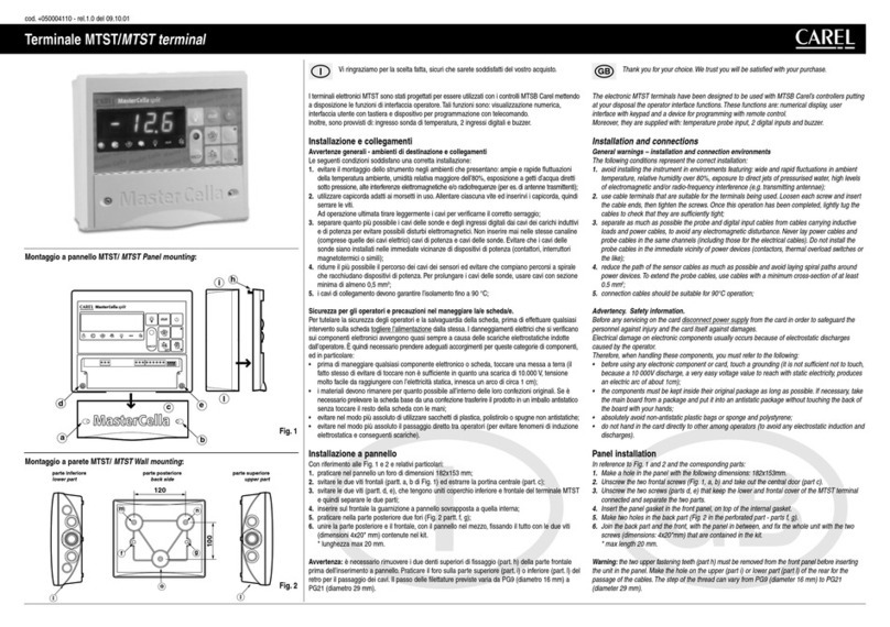
+050001950 - rel. 1.3 - 02.03.2020
Terminale utente pGDx Touch 7” -
User terminal pGDx Touch 7”
pGDx
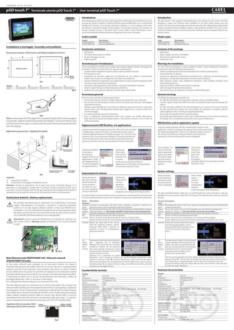
Introduzione
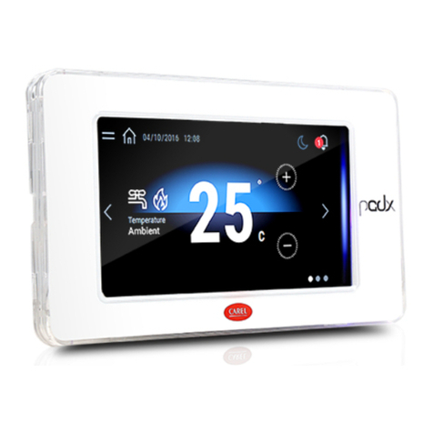
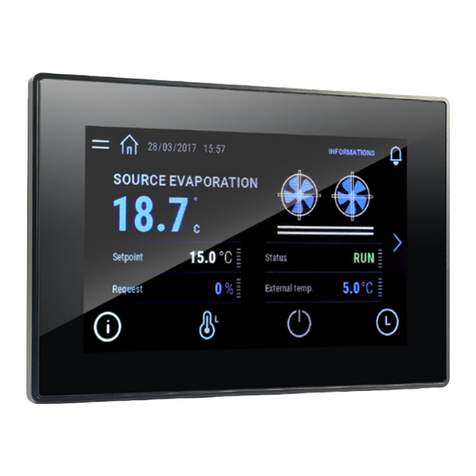
Il terminale grafico pGDx da 7 pollici appartiene alla famiglia di terminali touch screen
pensata per rendere semplice e intuitivo l’interfacciamento dell’utente con i controlli
della famiglia pCO Sistema. La tecnologia elettronica utilizzata e il display a 16.7M colori
permettono di gestire immagini di alta qualità e funzionalità avanzate per ottenere un
elevato standard estetico. Il pannello touch screen, inoltre, facilita l’interazione uomo-
macchina rendendo, di fatto, più facile la navigazione tra le varie schermate. A seconda
dei modelli, sono possibili diverse installazioni: a pannello, sia frontale che da retro, a muro
oppure ad incasso. In ogni caso è consentito sia l’orientamento orizzontale che verticale.
Codici modelli
Codice N. porte RS485 N. porte ETH Connettività Wi-Fi
PGR07****B*** 1 - -
PGR07****W*** 1 - ü
PGR07****D*** 2 - -
PGR07****C*** 1 1 -
PGR07****R*** 1 1 ü
PGR07****F*** 2 2 -
PGR07****G*** 2 2 ü
PGB07****E*** - 1 -
PGB07****M*** - 2 -
PGB07****I*** - 2 ü
Contenuto confezione
pGDx; connettori alimentazione e connettori RS485; kit di fissaggio; foglio istruzioni,
antenna Wi Fi (solo nei modelli che la prevedono, PG*07***D[G,I,R,W]***). Sono esclusi
invece: placchetta, alimentatore PGTA00TRX0 e scatole per il montaggio a muro.
Avvertenze per l’installazione
Per una installazione a regola d’arte rivolgersi ad installatori abilitati. Evitare il montaggio dei
terminali in ambienti che presentino le seguenti caratteristiche:
• umidità relativa maggiore di quanto indicato nelle specifiche tecniche;
• forti vibrazioni o urti;
• esposizione ad atmosfere aggressive ed inquinanti (es.: gas solforici e ammoniacali,
nebbie saline, fumi) con conseguente corrosione e/o ossidazione;
• elevate interferenze magnetiche e/o radiofrequenze (evitare quindi l’installazione delle
macchine vicino ad antenne trasmittenti);
• esposizione all’irraggiamento solare diretto e agli agenti atmosferici in genere;
• ampie e rapide fluttuazioni della temperatura ambiente;
• ambienti ove sono presenti esplosivi o miscele di gas infiammabili.
Devono essere rispettate le seguenti prescrizioni:
• con sonda temperatura/umidità a bordo si raccomanda di:
– utilizzare solo placchetta dotate di foro di aerazione
– installare il terminale lontano dai flussi d’aria proveniente da fonti di calore/
raffrescamento
– se installato in verticale, posizionare la sonda nella parte inferiore del display
• per le reti di comunicazione Ethernet e RS485 utilizzare esclusivamente cavi schermati;
• utilizzare una tensione di alimentazione pari a quella prescritta, al fine di evitare di
danneggiare in modo irreparabile il dispositivo;
• utilizzare capicorda adatti per i morsetti in uso. Allentare ogni vite ed inserirvi i capicorda,
quindi serrare le viti. Ad operazione ultimata tirare leggermente i cavi per verificarne il
corretto serraggio;
• nei modelli con antenna Wi-Fi esterna mantenere almeno un isolamento principale
(500 Vac secondo la IEC 60730-1) tra il connettore RP-SMA e la terra di protezione;
• non aprire il prodotto quando è alimentato;
• l’uso a temperature particolarmente basse può causare una visibile diminuzione
della velocità di risposta del display. Questo è da ritenersi normale e non è indice di
malfunzionamento.
• per una corretta installazione utilizzare una coppia di serraggio delle viti di 0.4 Nm. Inoltre,
nei modelli PG*07***[N,T]****, per raggiungere il grado di protezione IP dichiarato è
necessario che l’indice di rugosità del pannello non superi 1.6 μm e che la guarnizione
sia correttamente assemblata;
• evitare il contatto del prodotto con parti a tensioni pericolose.
• assicurarsi che i cavi siano opportunamente fissati in modo da evitare il contatto con
parti a tensioni pericolose nel caso di loro accidentale disconnessione.
Signicato colori notication bar
All’accensione la notification bar esegue una breve segnalazione di color blu per indicare
l’avvio della fase di boot. Le seguenti segnalazioni sono poi gestite dal programma
applicativo realizzato con c.touch.
Aggiornamento HMI Runtime e/o applicazione
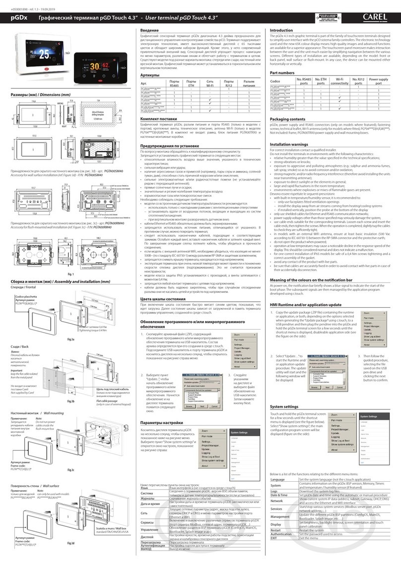
1. Copiare il pacchetto di aggiornamento (file .ZIP) contenente
il runtime o l’applicazione, oppure entrambi, a seconda
delle opzioni scelte al momento della generazione di
“Update package”con c.touch, in una chiavetta USB e
successivamente collegare la chiavetta al pGDx. Tenere
premuto il dito sullo schermo del terminale pGDx per alcuni
secondi fino a che il menu contestuale sarà visualizzato,
disabilitabile lato applicativo (Fig. a lato):
2. Selezionare
“Update…” per
avviare la procedura
di aggiornamento
Runtime e/o
applicazione. L’utility
per l’aggiornamento si
avvierà ed apparirà la
seguente finestra:
3. Seguire quindi la
procedura guidata
selezionando il
file inserito nella
chiavetta USB e
premendo il tasto
next per conferma.
Impostazioni di sistema
Tenere premuto il dito sullo schermo del
terminale pGDx per alcuni secondi fi no a
che il menu contestuale sarà visualizzato
(fig. sotto), Selezionare“Show system
settings”, apparirà la schermata principale
del programma di configurazione (fig a
lato):
Di seguito elencate le funzioni presenti nelle differenti voci del menù:
Language Impostazione della lingua di sistema (non dell’applicazione c.touch)
System Contiene informazioni su pGDx: Versione BSP, Memoria, Timers e
sensore tempearatura / umidità (se presente)
Logs Permette di scaricare i file di log del sistema
Date & Time Permette si settare data e ora di pGDx attraverso procedura
automatica o manuale
Network
Mostra gli attuali dati IP del sistema (indirizzo, subnet, Gateway,
DHCP, DNS) e permette di accedere al menu di configurazione della
porta Ethernet e dell’interfaccia Wi Fi
Services Permette di accendere/spegnere diversi servizi di sistema (Modbus
server port, indirizzo pGDx nella rete,…)
Management Permette di aggiornare le diverse partizioni BSP di pGDx (ConfigOS,
MainOS, Bootloader, Splash image, etc…)
Display Permette di impostare luminosità, backlight timeout, orientamento
dello schermo e calibrazione del touch panel
Restart Lancia un riavvio del sistema
Authentication Permette di impostare password per accesso
EXIT Permette uscire dal menù
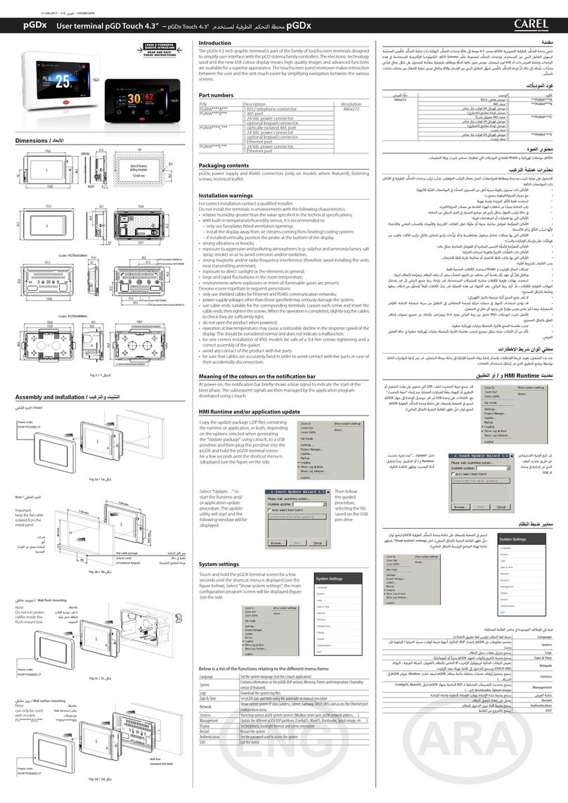
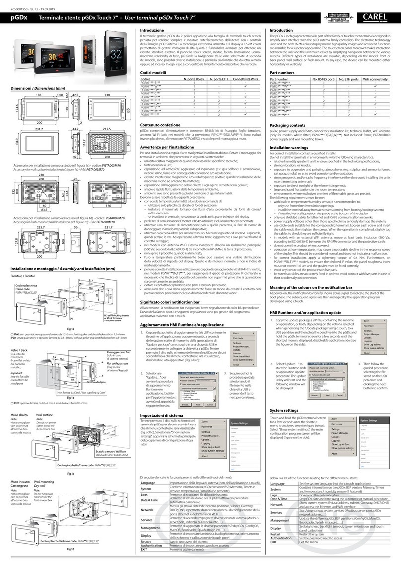
Dimensioni / Dimensions (mm)
183
200
231.7
10.8 42.5 230
212.5
200
2
9.7
130100
114.7
44.7
12.4100
124.6133.9
Accessorio per installazione a muro a sbalzo (rif. figura 1c) - codice: PGTA00SM70
Accessory for wall surface installation (ref. Figure 1c) - P/N: PGTA00SM70
230
28200
100
60
60 176
83.5
83.5
132
71
Accessorio per installazione a muro ad incasso (rif. figura 1d) - codice: PGTA00RM70
Accessory for ush-mounted wall installation (ref. Figure 1d) - P/N: PGTA00RM70
225.7
200
127.8
56 221.7
123.4
100
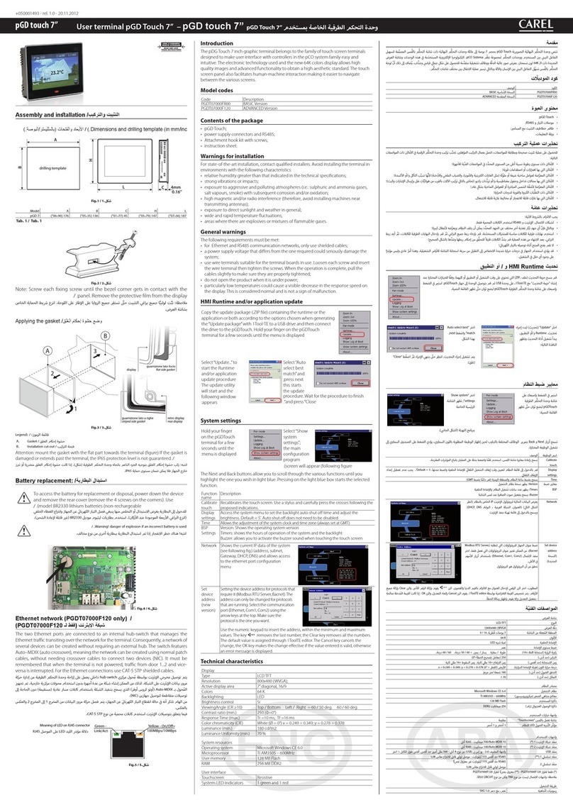
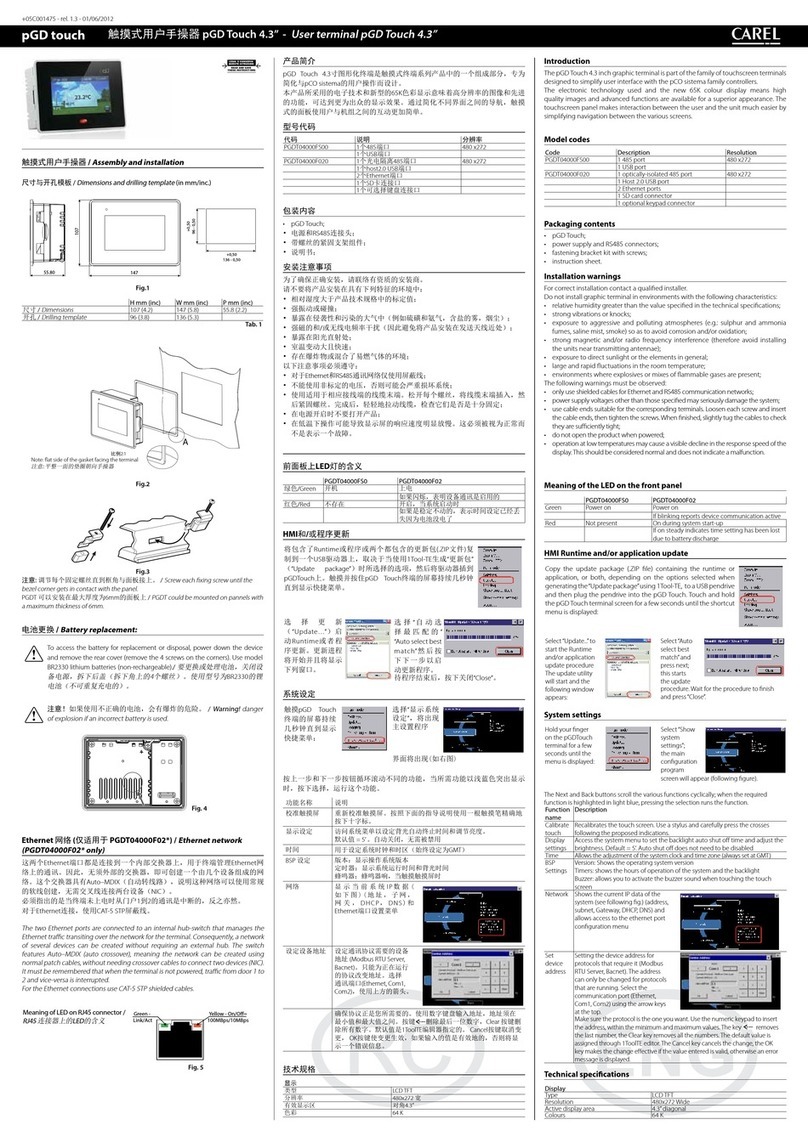
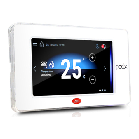
Introduction
The pGDx 7 inch graphic terminal is part of the family of touchscreen terminals designed to
simplify user interface with the pCO sistema family controllers. The electronic technology
used and the new 16.7M colour display means high quality images and advanced functions
are available for a superior appearance. The touchscreen panel moreover makes interaction
between the user and the unit much easier by simplifying navigation between the various
screens. Different types of installation are available, depending on the model: front or
back panel, wall surface or flush-mount. In any case, the device can be mounted either
horizontally or vertically.
Part numbers
Part number No. RS485 ports No. ETH ports WiFi connectivity
PGR07****B*** 1- -
PGR07****W*** 1- ü
PGR07****D*** 2- -
PGR07****C*** 11 -
PGR07****R*** 11 ü
PGR07****F*** 22 -
PGR07****G*** 22 ü
PGB07****E*** -1 -
PGB07****M*** -2 -
PGB07****I*** -2ü
Packaging contents
pGDx; power supply and RS485 connectors; installation kit; technical leaflet, WiFi antenna
(only for models where fitted, PG*07***D[G,I,R,W]***). Not included: frame, PGTA00TRX0
power supply and wall mounting boxes.
Installation warnings
For correct installation contact a qualified installer.
Do not install the terminals in environments with the following characteristics:
• relative humidity greater than the value specified in the technical specifications;
• strong vibrations or knocks;
• exposure to aggressive and polluting atmospheres (e.g.: sulphur and ammonia fumes,
salt spray, smoke) so as to avoid corrosion and/or oxidation;
• strong magnetic and/or radio frequency interference (therefore avoid installing the units
near transmitting antennae);
• exposure to direct sunlight or the elements in general;
• large and rapid fluctuations in the room temperature;
• environments where explosives or mixes of flammable gases are present.
The following requirements must be met
• with built-in temperature/humidity sensor, it is recommended to:
– only use frame fitted ventilation openings
– install the terminal away from air streams coming from heating/cooling systems
– if installed vertically, position the probe at the bottom of the display
• only use shielded cables for Ethernet and RS485 communication networks;
• power supply voltages other than those specified may seriously damage the system;
• use cable ends suitable for the corresponding terminals. Loosen each screw and insert
the cable ends, then tighten the screws. When the operation is completed, slightly tug
the cables to check they are sufficiently tight;
• in models with an external WiFi antenna, ensure at least basic insulation (500 Vac
according to IEC 60730-1) between the RP-SMA connector and the protective earth;
• do not open the product when powered;
• operation at low temperatures may cause a noticeable decline in the response speed
of the display. This should be considered normal and does not indicate a malfunction.
• for correct installation, apply a tightening torque of 0.4 Nm. Furthermore, on
PG*07***[N,T]**** models, to ensure the declared IP value, the panel roughness index
must not exceed 1.6 μm and the gasket must be fitted correctly;
• avoid any contact of the product with live parts.
• be sure that cables are accurately fixed in order to avoid contact with live parts in case of
their accidentally disconnection.
Meaning of the colours on the notication bar
At power-on, the notification bar briefly shows a blue signal to indicate the start of the
boot phase. The subsequent signals are then managed by the application program
developed using c.touch.
HMI Runtime and/or application update
1. Copy the update package (.ZIP file) containing the runtime
or application, or both, depending on the options selected
when generating the “Update package”using c.touch, to a
USB pendrive and then plug the pendrive into the pGDx and
hold the pGDx terminal screen for a few seconds until the
shortcut menu is displayed, disableable application side (see
the figure on the side):
2. Select “Update…” to
start the Runtime and/
or application update
procedure. The update
utility will start and the
following window will
be displayed:
3. Then follow the
guided procedure,
selecting the file
saved on the USB
pen drive and
clicking the next
button to confirm.
System settings
Touch and hold the pGDx terminal screen
for a few seconds until the shortcut
menu is displayed (see the figure below).
Select “Show system settings”; the main
configuration program screen will be
displayed (figure on the side):
Below is a list of the functions relating to the different menu items:
Language Set the system language (not the c.touch application)
System Contains information on the pGDx: BSP version, Memory, Timers
and temperature / humidity sensor (if featured)
Logs Download the system log files
Date & Time Set pGDx date and time using the automatic or manual procedure
Network Show current system IP data (address, subnet, Gateway, DHCP, DNS)
and access the Ethernet and WiFi interface
Services Start/stop various system services (Modbus server port, pGDx
network address,…)
Management Update the different pGDx BSP partitions (ConfigOS, MainOS,
Bootloader, Splash image, etc.…)
Display Set brightness, backlight timeout, screen orientation and touch
panel calibration
Restart Restart the system
Authentication Set the password used to access
EXIT Exit the menu
Frontale / Frontal
200
188
213
115.5
100
88
M3 self-blocking inserts
or Ø 4.2 for screw
+ counter-screw
Fig.1a
(*) IP66: con guarnizione e spessore lamiera da 1.2÷6 mm / with gasket and sheet thickness from 1.2 - 6 mm
IP20: senza guarnizione e spessore lamiera da 0.8÷6 mm / without gasket and sheet thickness from 0.8 - 6 mm
Retro / Back
M3 threaded pins
184
200
10.4
5.4
125.6
100
R4
125.6
100
policarbonate
Fig.1b
(*) IP20: spessore lamiera da 0.8÷2 mm / sheet thickness from 0.8 - 2 mm
Muro sbalzo Wall surface
Fig.1c
Muro incasso/ Wall mounting
Cartongesso Dry wall
220
122
Fig.1d
Passaggio cavo at
(solo in caso
di tastiera esterna)
Flat cable passage
(only in case
of external keypad)
Codice placchetta/Frame code: PGTA**F[T,H][2,3]*
Non fornita da Carel / Not supplied by Carel
Nota:
Non convogliare
cavi di potenza
all’interno dela
scatola da incasso
Note:
Do not run power
cables inside the
ush-mount box
Importante:
mantenere
il cavo flat isolato
dal pannello
metallico
Important:
keep the at cable
isolated from the
metal panel
Scatola a muro / Wall box
standard ITA/CHN/DEU/USA
Codice placchetta
Frame code:
PGTA**F[B,W][2,3]*
(*)
Installazione e montaggio /
Assembly and installation (mm)
Codice placchetta/Frame code: PGTA**F[T,H][2,3]*
Nota:
Non convogliare
cavi di potenza
all’interno dela
scatola da incasso
Note:
Do not run power
cables inside the
ush-mount box
Smaltimento del prodotto: L’apparecchiatura (o il prodotto) deve essere oggetto di raccolta separata in
conformità alle vigenti normative locali in materia di smaltimento. /
Disposal of the product: The appliance
(or the product) must be disposed of separately in compliance with the local standards in force on waste
disposal.
CAREL Industries HQs
Via dell’Industria, 11 - 35020 Brugine - Padova (Italy)
Tel. (+39) 0499716611 – Fax (+39) 0499716600 – www.carel.com – e-mail: [email protected] +050001950 - rel. 1.3 - 02.03.2020
CAREL si riserva la possibilità di apportare modifiche o cambiamenti ai propri prodotti senza alcun preavviso.
CAREL INDUSTRIES reserves the right to modify the features of its products without prior notice.
Caratteristiche tecniche
Display
Tipo LCD TFT
Risoluzione 800x480 Wide
Area attiva del display 7” diagonale
Colori 16.7M
Retro-illuminazione LED - Lifetime 20 khrs @ 25 °C
Regolazione luminosità Si - auto spegnimento di default dopo 15 min
Angolo visivo (CR ≥10) Alto/Basso (50/70 deg.) - Sinistra/Destra (70/70 deg.)
Contrasto (tipico) 400 (Φ=0°)
Luminosità (tipico) 500 cd/m2
Interfaccia utente
Touchscreen Resistivo
Indicatori LED sistema Notification bar a 8 colori
Interfacce
Porte Ethernet ETH0, ETH1 Auto-MDIX 10/100 Mbit - RJ45 femmina
Cavo STP CAT 5 Lmax = 100m
Wi-Fi IEEE 802.11 b/g/n - STATION/ACCESS POINT mode
Antenna integrata/esterna a seconda dei modelli
Max Transmit Power = 17dBm
Remotazione antenna esterna Lmax = 2 m
Connettore antenna esterna RP-SMA femmina
(per modelli PG*07***D[G,I,R,W]***)
Porta USB () Host interface 2.0 - micro USB -B - 150 mA max (non
utilizzare per ricaricare dispositivi) Lmax = 1m
Porte Seriali, COM1 (), COM2 RS485 max 115,2 Kb/s
Connettore sconnettibile a vite passo 3,81mm
Cavo schermato AWG 20-22 a coppie ritorte per ±
Lmax = 500m - coppia serraggio 0,25Nm (2.2lbf x in)
Master/Slave configurabile tramite dip switch (Fig.3)
Sonda temperatura / umidità 0...50 °C / 20...80% rH
0...50 °C ±1 °C (in aria statica)
20...80% ±5% (in aria statica)
() solo per manutenzione. La porta USB può essere danneggiato da ESD (Scariche
Elettrostatiche). Si consiglia di adottare le opportune precauzioni al fine di evitarne la rottura.
() optoisolata per modello PGR07****[C,D,F,G,R]***
Funzionalità
Grafica vettoriale Si, incluso supporto SVG 1.0
Oggetti dinamici Si Visibilità, posizione, rotazione
TrueType fonts Si
Multiprotocollo Si
Storico e trend Si. Limitato alla capacità della Flash memory
Multi-lingue Si, con impostazione della lingua run-time e limitato
solo dalla memoria disponibile
Recipes (ricette) Si. Limitato alla capacità della Flash memory
Allarmi Si
Lista event Si
Passwords Si
Real Time Clock () Si, con batteria di back-up
Screen saver Si
Buzzer () “Beep” alla pressione del touch (configurabile)
() solo per i modelli che lo prevedono
Elettriche
Alimentazione 24Vdc Classe 2/SELV fornita tramite accessorio
PGTA00TRX0 - Lmax = 50 m (-) - sezione cavo
AWG 12-20 - coppia serraggio 0.8 Nm (7 lbf x in)
Massima potenza assorbita 9 W
Fusibile Automatico
Peso Approx 600 g
Batteria Non ricaricabile al litio mod BR1225
Classe e struttura del software A
Scopo del dispositivo dispositivo di comando di funzionamento
Costruzione del controllo incorporato (PG*07*** [D,F,N,T,W]****)
Tipo di azione automatica azione tipo 1
Resistenza al calore e al fuoco Cat. D
Immunità contro le sovratensioni Cat. III
Classe isolamento Classe III
() Per i modelli PG*07***W**** installati ad incasso l’accessorio PGTA00TRX0 deve essere
installato in una scatola dedicata - () Range di alimentazione: 24 Vdc ± 10%
Condizioni ambientali
Temperatura di lavoro PG*07***[D,N,T]****: -20T60 °C
PG*07***[F,W]****: 0T50 °C
Temperatura di immagazzinam. PG*07********: -30T70 °C
Umidità relativa massima di lavoro
e immagazzinamento
85% @ 40 °C non-condensante
Grado di protezione PG*07***T****: IP66, NEMA Type 1 (frontale)
PG*07***N****: IP66, NEMA Type 4X indoor (frontale)
se accoppiato all’accessorio PGTA**F [B,W][2,3]* (placch.)
PG*07***[D,F,W]****: IP20, NEMA Type 1 (frontale)
Grado di inquinamento 3
Technical specications
Display
Type LCD TFT
Resolution 800x480 Wide
Active display area 7”diagonal
Colours 16,7M
Backlighting LED - Lifetime 20 khrs @ 25 °C
Brightness control Yes - auto-off by default after 15 min
Visual angle (CR ≥10) Up/Down (50/70 deg.) - Left/Right (70/70 deg.)
Contrast (typical) 400 (Φ=0°)
Brightness (typical) 500 cd/m2
User interface
Touchscreen Resistive
System signal LEDs 8-colour notification bar
Interfaces
ETH0, ETH1 Ethernet ports Auto-MDIX 10/100 Mbit - RJ45 female
STP CAT 5 cable Lmax = 100 m
Wi-Fi IEEE 802.11 b/g/n - STATION/ACCESS POINT mode
Built-in/external antenna based on model
Max Transmit Power = 17dBm
External antenna remote mounting Lmax = 2 m
External antenna connector RP-SMA female
(for models PG*07***D[G,I,R,W]***)
USB port () Host interface 2.0 - micro USB -B - 150 mA max
(do not use to charge devices) - Lmax = 1m
COM1 (), COM2 Serial ports RS485 max 115,2 Kb/s
Removable screw connector 3,81mm pitch
Shielded twisted pair cable AWG 20-22 for ±
Lmax = 500m - tightening torque 0.25Nm (2.2lbf x in)
Master/Slave set via dipswitch (Fig.3)
Temperature / humidity probe 0 to 50 °C / 20 to 80% rH
0 to 50 °C ±1 °C (static air)
20 to 80% ±5% (static air)
() only for service. The USB port can be damaged by ESD (Electro-Static Discharges).
It’s recommended to adopt appropriate precautions in order to avoid failures.
() opto-isolated for model PGR07****[C,D,F,G,R]***
Functions
Vector graphics Yes, includes SVG 1.0 support
Dynamic objects Yes Visibility, position, rotation
TrueType fonts Yes
Multi-protocol Yes
Logs and trends Yes. Limited to Flash memory capacity
Multilanguage Yes, run-time language setting and limited only by
available memory
Recipes Yes. Limited to Flash memory capacity
Alarms Yes
Event list Yes
Passwords Yes
Real Time Clock () Yes, with backup battery
Screen saver Yes
Buzzer () “Beep” when pressing the touchscreen (settable)
() only on models where featured
Electrical
Power supply 24Vdc Class 2/SELV supplied by PGTA00TRX0 accessory
Lmax = 50 m (-)- cable cross section AWG 12-20
tightening torque 0.8 Nm (7 lbf x in)
Max Power Absorption 9 W
Fuse Automatic
Weight Approx. 600 g
Battery Non-rechargeable lithium model BR1225
Software class and structure A
Purpose of control operation control
Controller construction incorporated control (PG*07***[D,F,N,T,W]****)
Type of automatic action type 1 action
Heat and fire resistance Cat. D
Overvoltage category Cat. III
Insulation class Class III
() For PG*07***W**** models with flush mounting, accessory PGTA00TRX0 must be
installed in a dedicated box - () Power supply range: 24 Vdc ± 10%
Environmental conditions
Operating temperature PG*07***[D,N,T]****: -20 to 60 °C
PG*07***[F,W]****: 0 to 50 °C
Storage temperature PG*07********: -30 to 70 °C
Maximum operating and
storage relative humidity
85% @ 40 °C non-condensing
Ingress protection PG*07***T****: IP66, NEMA Type 1 (front)
PG*07***N****: IP66, NEMA Type 4X indoor (front)
if coupled with PGTA**F [B,W][2,3]* (frame)
PG*07***[D,F,W]****: IP20, NEMA Type 1 (front)
Pollution degree 3
1 3 5
710 9 8 114 2
6
SW2
SW1
Fig.2
Mounting Connectivity
Description
PG*07***[F,T]****
Front Panel
PG*07***N****
Front Panel
PG*07***D****
Rear Panel
PG*07***W****
Wall Mounting
PGR07****[B/W]***
PGR07****D***
PGR07****[C/R]***
PGR07****[F/G]***
PG*07****E***
PG*07****[I/M]***
1MicroUSB rear 
2MicroUSB front 
3external keypad connector 
4temperature and humidity probe () 
(option)
5Wi-Fi antenna SMA connector (RP-SMA) 
6RS485 port COM1 
7RS485 port COM2 
8Ethernet port ETH0 
9Ethernet port ETH1 
10 notication bar 
11 power supply     
Tab. 2
Se la porta COM1 è usata come pLAN (Modbus over pLAN) o display port: NON collegare le
resistenze di terminazione da 120 ohm sul primo e sull’ultimo dispositivo della rete. Il numero
massimo di dispositivi collegabili nella rete è 32 e la lunghezza massima della rete è 500m.
Attenzione: solo la porta COM1 può essere utilizzata come pLAN (prot. Modbus over pLAN)
() Verificare periodicamente la corretta pulizia dei fori di areazione della sonda.
If COM1 port is used as pLAN (Modbus over pLAN) or display port: DO NOT connect the
resistors 120 ohm termination on the first and last device in the network. The maximum
number of devices that can be connected in the network is 32 and the maximum length
of the network is 500m.
Attention: only COM1 port can be used as a pLAN (Modbus over pLAN protocol).
() Periodically check that the probe ventilation holes are clean.
Congurazione Dipswitch Seriale
/ Serial
Dipswitch Conguration
SLAVE MASTER
Fig.3
resistenza di terminazione
terminator resistor
120 ohm - OFF 123
ON
123
ON
123
ON
123
ON
Pull-Up
Pull-Down - OFF
Pull-Up
Pull-Down - ON
(pLAN)
resistenza di terminazione
terminator resistor
120 ohm - ON
J1 J2 J3 J4 J5
J14
J10
J13
J12 J15
dracSMBdracsuBdleiF
4321
J11 pLAN
Tx/Rx
GND
J26 FBus2
J24
+
XXXXXXXXXXXX
ETH0 ETH0
c.pCO/pCO
Access-Point/Station
J1 J2 J3 J4 J5
J14
J10
J13
J12 J15
dracSMBdracsuBdleiF
4321
J11 pLAN
J25 BMS2 J26 FBus2
J24
+
XXXXXXXXXXXX
c.pCO
J1 J2 J3 J4 J5
J14
J10
J13
J12 J15
dracSMBdracsuBdleiF
4321
Tx/Rx GND
J25 BMS2 J26 FBus2
J24
+
XXXXXXXXXXXX
c.pCO/pCO
GND
–
+
LN
+–
PGTA00TRX0
230 Vac
24 Vdc
+
–
GND
–
+
J25 BMS2
J11 pLAN
COM1
COM2
J1 J2 J3 J4 J5
J14
J10
J13
J12 J15
dracSMBdracsuBdleiF
4321
J11 pLAN
Tx/Rx
GND
J26 FBus2
J24
+
XXXXXXXXXXXX
c.pCO/pCO
Access-Point/Station
c.pCO mini
J1 J2 J3 J4 J5
J14
J10
J13
J12 J15
dracSMBdracsuBdleiF
4321
Tx/Rx GND
J25 BMS2
Tx/Rx
GND Tx/Rx
GND
J26 FBus2
J24
+
XXXXXXXXXXXX
c.pCO/pCO
GND
–
+
LN
+–
PGTA00TRX0
230 Vac
24 Vdc
+
–
GND
–
+
ETH1 ETH0
J25 BMS2
J11 pLAN
COM1
COM2
Congurazione Switch Ethernet
Ethernet switch conguration
Congurazione Dual MAC Ethernet
Dual MAC Ethernet conguration
Fig. 4a Fig. 4b
Collegamenti elettrici /
Network connection:
Schema per collegamento a pCO/c.pCO /
Connection to
pCO/c.pCO
Frontale NEMA 4X / NEMA 4X Frontal
214
R2
116
Fig.1e
Codice placchetta
Frame code:
PGTA**F[B,W][2,3]*
Spessore lamiera da 1.2÷6 mm
Sheet thickness from 1.2 - 6 mm
IMPORTANT WARNINGS: The CAREL product is a state-of-the-art product, whose operation is specified in the
technical documentation supplied with the product or can be downloaded, even prior to purchase, from the website
www.carel.com. - The client (builder, developer or installer of the final equipment) assumes every responsibility and
risk relating to the phase of configuration the product in order to reach the expected results in relation to the specific
final installation and/or equipment. The lack of such phase of study, which is requested/indicated in the user manual,
can cause the final product to malfunction of which CAREL can not be held responsible. The final client must use the
product only in the manner described in the documentation related to the product itself.The liability of CAREL in relation
to its own product is regulated by CAREL’s general contract conditions edited on the website www.carel.com and/or by
specific agreements with clients.
AVVERTENZE IMPORTANTI: Il prodotto CAREL è un prodotto avanzato, il cui funzionamento è specificato nella
documentazione tecnica fornita col prodotto o scaricabile, anche anteriormente all’acquisto, dal sito internet www.carel.
com. Il cliente (costruttore, progettista o installatore dell’equipaggiamento finale) si assume ogni responsabilità e rischio
in relazione alla fase di configurazione del prodotto per il raggiungimento dei risultati previsti in relazione all’installazione
e/o equipaggiamento finale specifico. La mancanza di tale fase di studio, la quale è richiesta/indicata nel manuale d’uso,
può generare malfunzionamenti nei prodotti finali di cui CAREL non potrà essere ritenuta responsabile. Il cliente finale
deve usare il prodotto solo nelle modalità descritte nella documentazione relativa al prodotto stesso. La responsabilità di
CAREL in relazione al proprio prodotto è regolata dalle condizioni generali di contratto CAREL editate nel sito www.carel.
com e/o da specifici accordi con i clienti.
Normative
Sicurezza UL UL60730-1
sch. CB IEC60730-1
EMC CE EN61000-6-1 / EN61000-6-2
EN61000-6-3 / EN61000-6-4
EN55014-1 / EN55014-2
Radio
TECH.CODE /
MODEL
PGDX07001
PGDX07002
Red EN301489-1/EN301489-17
EN300328
FCC Part.15 Subpart.B
SRRC CMIIT ID: 2019DJ11468 (for PGDX07001)
2019DJ12094 (for PGDX07002)
ANATEL ID: 09607-19-05684
Questa apparecchiatura non ha diritto alla
protezione da interferenze dannose e non deve
causare interferenze in sistemi debitamente
autorizzati
Altre certificazioni sono in corso di approvazione, si prega di contattare Carel
HQs per altri dettagli
NO POWER
& SIGNAL
CABLES
TOGETHER
READ CAREFULLY IN THE TEXT!
Mantenere
sempre in
canaline separate
i cavi di segnale
dai cavi di
potenza.
Standards
Safety UL UL60730-1
sch. CB IEC60730-1
EMC CE EN61000-6-1 / EN61000-6-2
EN61000-6-3 / EN61000-6-4
EN55014-1 / EN55014-2
Radio
TECH.CODE /
MODEL
PGDX07001
PGDX07002
Red EN301489-1/EN301489-17
EN300328
FCC Part.15 Subpart.B
SRRC CMIIT ID: 2019DJ11468 (for PGDX07001)
2019DJ12094 (for PGDX07002)
ANATEL ID: 09607-19-05684
This equipment is not entitled to protection
against harmful interference and may not cause
interference in duly authorized systems.
Other certification under approvals, please contact Carel Representatives for
other details
NO POWER
& SIGNAL
CABLES
TOGETHER
READ CAREFULLY IN THE TEXT!
Always keep the
signal cables
and power cable
in separate
conduits.

Other Carel Touch Terminal manuals

Carel EasySet HYPW User manual

Carel

Carel EasySet HYPW User manual

Carel pGDx User manual

Carel

Carel pGDx User manual

Carel PAD User manual

Carel

Carel PAD User manual

Carel AX5000 User manual

Carel

Carel AX5000 User manual

Carel pGD Touch Instruction Manual

Carel

Carel pGD Touch Instruction Manual

Carel IR U Series User manual

Carel

Carel IR U Series User manual

Carel pGD touch 7 User manual

Carel

Carel pGD touch 7 User manual

Carel pGD touch Instruction Manual

Carel

Carel pGD touch Instruction Manual

Carel pGDx Touch 4.3 User manual

Carel

Carel pGDx Touch 4.3 User manual

Carel PAD User manual

Carel

Carel PAD User manual

Carel pGD Series User manual

Carel

Carel pGD Series User manual

Carel pGD Touch User manual

Carel

Carel pGD Touch User manual

Carel PLD Series User manual

Carel

Carel PLD Series User manual

Carel pGDx User manual

Carel

Carel pGDx User manual

Carel TH Tune User manual

Carel

Carel TH Tune User manual

Carel pGDx Touch 4.3” User manual

Carel

Carel pGDx Touch 4.3” User manual

Carel pGDx Series Instruction Manual

Carel

Carel pGDx Series Instruction Manual

Carel pGD Series User manual

Carel

Carel pGD Series User manual

Carel pGD touch PGDT04000FS00 Instruction Manual

Carel

Carel pGD touch PGDT04000FS00 Instruction Manual

Carel AX3000 Series User manual

Carel

Carel AX3000 Series User manual

Carel pGD 7 Series User manual

Carel

Carel pGD 7 Series User manual

Carel MTST User manual

Carel

Carel MTST User manual

Carel pGD Series User manual

Carel

Carel pGD Series User manual

Carel pGD Series User manual

Carel

Carel pGD Series User manual

Popular Touch Terminal manuals by other brands

nvent Raychem NGC-30 installation manual

nvent

nvent Raychem NGC-30 installation manual

Festo CPV-GE-ASI-8E6A-Z Series Brief description

Festo

Festo CPV-GE-ASI-8E6A-Z Series Brief description

Motorola MK3000 Quick reference guide

Motorola

Motorola MK3000 Quick reference guide

Ingenico group Desk Series user guide

Ingenico group

Ingenico group Desk Series user guide

M2I TOPR Series Hardware manual

M2I

M2I TOPR Series Hardware manual

Avalue Technology RiPac-10P1 user manual

Avalue Technology

Avalue Technology RiPac-10P1 user manual

HP RP7 Model 7800 Illustrated Parts and Service Map

HP

HP RP7 Model 7800 Illustrated Parts and Service Map

ABB SACE Tmax XT instruction manual

ABB

ABB SACE Tmax XT instruction manual

Advantech POC-176 user manual

Advantech

Advantech POC-176 user manual

ZKTeco S922 Series user guide

ZKTeco

ZKTeco S922 Series user guide

First Data FD130 Quick reference guide

First Data

First Data FD130 Quick reference guide

Rockwell Automation Allen-Bradley 2711-TBDC installation instructions

Rockwell Automation

Rockwell Automation Allen-Bradley 2711-TBDC installation instructions

Festo CPX-FB13 Electronic manual

Festo

Festo CPX-FB13 Electronic manual

iPhotonix 7261G installation guide

iPhotonix

iPhotonix 7261G installation guide

Solux SX-DT-900 user manual

Solux

Solux SX-DT-900 user manual

Johnson Controls FlexSys MIT3-CN Installation & operation manual

Johnson Controls

Johnson Controls FlexSys MIT3-CN Installation & operation manual

GRUP ARGE HT E21 user manual

GRUP ARGE

GRUP ARGE HT E21 user manual

Siemens SIDATA 9756 installation manual

Siemens

Siemens SIDATA 9756 installation manual

manuals.online logo
manuals.online logoBrands
  • About & Mission
  • Contact us
  • Privacy Policy
  • Terms and Conditions

Copyright 2025 Manuals.Online. All Rights Reserved.