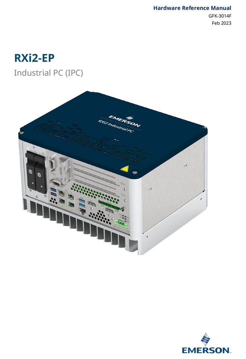
Emerson RXi2-XP Quick user guide

Hardware Reference Manual
GFK-3022E
September 2021
RXi2-XP
Industrial PC (IPC)

Hardware Reference Manual Document-History
GFK-3022E September 2021
Document-History
Rev
Date
Description
A
2019-05-
Initial version
B
2019-09-
Emerson rebranding
C
2019-11-
Emerson rebranding
D
2021-03
Update to IEC/UL 62368
E
2021-09
UKCA Update

Warnings and Caution Notes as Used in this Publication
WARNING
Warning notices are used in this publication to emphasize that hazardous voltages, currents, temperatures, or
other conditions that could cause personal injury exist in this equipment or may be associated with its use.
In situations where inattention could cause either personal injury or damage to equipment, a Warning notice is
used.
CAUTION
Caution notices are used where equipment might be damaged if care is not taken.
ATTENTION
Indicates a procedure or condition that should be strictly followed to improve these applications.
Note: Notes merely call attention to information that is especially significant to understanding and operating the
equipment.
These instructions do not purport to cover all details or variations in equipment, nor to provide for every
possible contingency to be met during installation, operation, and maintenance. The information is
supplied for informational purposes only, and Emerson makes no warranty as to the accuracy of the
information included herein. Changes, modifications, and/or improvements to equipment and
specifications are made periodically and these changes may or may not be reflected herein. It is
understood that Emerson may make changes, modifications, or improvements to the equipment
referenced herein or to the document itself at any time. This document is intended for trained personnel
familiar with the Emerson products referenced herein.
Emerson may have patents or pending patent applications covering subject matter in this document. The
furnishing of this document does not provide any license whatsoever to any of these patents.
Emerson provides the following document and the information included therein as-is and without
warranty of any kind, expressed or implied, including but not limited to any implied statutory warranty of
merchantability or fitness for particular purpose.
© 2021 Emerson. All rights reserved.
Emerson Terms and Conditions of Sale are available upon request. The Emerson logo is a trademark and
service mark of Emerson Electric Co. All other marks are the property of their respective owners.

Preface
Legal Information
Legal Disclaimers
© 2021 Emerson Automation Solutions, Inc. All rights reserved.
The information in this manual is proprietary to and is the confidential information of Emerson
Automation Solutions, Inc. and may not be reproduced in whole or in part, for any purpose, in
any form or by any means, electronic, mechanical, recording, or otherwise, without written
consent of Emerson Automation Solutions, Inc. Use, disclosure, and reproduction is permitted
only under the terms of a Emerson Automation Solutions license agreement or explicit written
permission of Emerson Automation Solutions. You are not authorized to use this document or
its contents until you have read and agreed to the applicable license agreement. Receipt of this
publication is considered acceptance of these conditions.
All information contained in this document has been carefully checked and is believed to be
entirely reliable and consistent with the product that it describes. However, no responsibility is
assumed for inaccuracies. Emerson Automation Solutions assumes no liability due to the
application or use of any product or circuit described herein; no liability is accepted concerning
the use of Emerson Automation Solutions products in life support systems. Emerson Automation
Solutions reserves the right to make changes to any product and product documentation in an
effort to improve performance, reliability, or design.
THIS DOCUMENT AND ITS CONTENTS ARE PROVIDED AS IS, WITH NO WARRANTIES OF ANY KIND,
WHETHER EXPRESS OR IMPLIED, INCLUDING WARRANTIES OF DESIGN, MERCHANTABILITY, AND
FITNESS FOR A PARTICULAR PURPOSE, OR ARISING FROM ANY COURSE OF DEALING, USAGE, OR
TRADE PRACTICE.
Changes or modifications to this unit, not expressly approved by Emerson Automation Solutions,
could void the user’s authority to operate the equipment.
All computer code and software contained in this document is licensed to be used only in
connection with a Emerson Automation Solutions hardware product. Even if this code or
software is merged with any other code or software program, it remains subject to the terms
and conditions of this license. If you copy, or merge, this code or software, you must reproduce
and include all Emerson Automation Solutions copyright notices and any other proprietary rights
notices.
The content of this manual if furnished for informational use only and is subject to change
without notice. Reverse engineering of any Emerson Automation Solutions product is strictly
prohibited.
In no event will Emerson Automation Solutions be liable for any lost revenue or profits or other
special, indirect, incidental and consequential damage, even if Emerson Automation Solutions
has been advised of the possibility of such damages, as a result of the usage of this document
describes. The entire liability of Emerson Automation Solutions shall be limited to the amount
paid by you for this document and its contents.
Emerson Automation Solutions shall have no liability with respect to the infringement of
copyrights, trade secrets, or any patents by this document of any part thereof. Please see the
applicable software license agreement for full disclaimer or warranties and limitations of
liability.
This disclaimer of warranty extends to Emerson Automation Solutions’ licensees, to licensees
transfers, and to licensees customers or users and is in lieu of all warranties expressed, implied,
or statutory, included implied warranties of scalability or fitness for a particular purpose.
The Emerson logo is a trademark of Emerson, Inc. Other brand names and product names
contained herein may be claimed as the property of others.
Emerson Automation Solutions, Inc., 2500 Austin Drive, Charlottesville, VA 22911, U.S.A.
Regulatory compliance
Products sold or transferred between companies or operated on company premises (factory
floor, laboratory) do not need CE, FCC or equivalent certification. Boards or subsystems which
cannot provide a useful function on their own do not need certification.
Certification can only be granted to complete and operational systems. There are authorized
testing agencies, regulatory organizations and laboratories who will issue certificates of
compliance after system testing.
Emerson Automation Solutions designs and tests all their products for EMI/EMC conformance.
Where Emerson Automation Solutions supplies a complete/functional system for use by end
users a certificate will be cited in the manuals/documents which are provided with the products.
Products manufactured by Emerson Automation Solutions should normally be suitable for use
in properly designed and produced customer equipment (system boxes or operational systems)
without any major redesign or additional filtering. However, the systems might not conform to
specific regulations once assembled and used. The system integrator or installer must test for
compliance as required in his country or by the intended application and certify this to the end
user.
ESD/EMI issues
ESD (Electro‐Static Discharge) and EMI (Electro‐Magnetic Interference) issues may show up in
complete and operational systems. There are many ways to avoid problems with these issues.
Any operational system with cables for I/O signals, connectivity or peripheral devices provides
an entry point for ESD and EMI. If Emerson Automation Solutions does not manufacture the
complete system, including enclosure and cables, it is the responsibility of the system integrator
and end user to protect their system against potential problems. Filtering, optical isolation, ESD
gaskets and other measures might be required at the physical point of entry (enclosure wall of
box or rack). For example it is state‐of‐the‐art that protection cannot be done at the internal
connector of an RTM if a cable is attached and routed outside the enclosure. It has to be done
at the physical entry point as specified above.
Products manufactured by Emerson Automation Solutions should normally be suitable for use
in properly designed and produced customer equipment (system boxes or operational systems)
without any major redesign. However, the systems might be subject to problems and issues once
assembled, cabled and used. The end user, system integrator or installer must test for possible
problems and in some cases show compliance to local regulations as required in his country or
by the intended application.

Waste Disposal
The mark or symbol on any electrical or electronic product shows that this product may not be
disposed off in a trash bin. Such goods have to be returned to the original vendor or to a properly
authorized collection point.
The black bar underneath the waste bin symbol shows that the product was placed on the
market after 13 August 2005. Alternatively the date of ‘placed on the market’ is shown in place
of the bar symbol.
CE conformance declaration
CE certification is required in EU countries for equipment which is used or operated by the end
user. Products sold or transferred between companies or operated on company premises
(factory floor, laboratory) do not need CE certification.
CE certification can only be granted to complete and operational systems. Boards or subsystems
which cannot provide a useful function on their own do not need CE certification.
Emerson Automation Solutions designs and tests all their products for EMI/EMC conformance.
Products manufactured by Emerson Automation Solutions should normally be suitable for use
in properly designed and produced customer equipment (system boxes or operational systems)
without any major redesign or additional filtering. The system integrator or installer must, in any
case, test for CE compliance and certify this to the end user.
Where Emerson Automation Solutions supplies a complete/functional system for use by end
users in EU countries a CE certificate will be cited in the manuals/documents which are provided
with the products. The CE (and year of certification) symbol is shown on the equipment, typically
on the type or S/N label or close to the power cable entry.
Emerson Automation Solutions have tested their boards using their own card cages (chassis).
Test results of these tests are available upon request.

Corporate addresses
Corporate headquarters
ICC Intelligent Platforms, Inc.
2500 Austin Drive
Charlottesville, VA 22911
U.S.A.
Phone: +1‐800‐322‐3616
Web: https://www.emerson.com/
Germany
US
ICC Intelligent Platforms GmbH
Memminger Str. 14
86159 Augsburg
Germany
ICC Intelligent Platforms, Inc.
2500 Austin Drive
Charlottesville, VA 22911
U.S.A.
Phone: +49-821-5034-0
Fax: +49-821-5034-119
Phone: +1-800-322-3616
ICC Intelligent Platforms on the Web:
https://www.emerson.com/
For contact and other information (service, warranty, support etc.) see address list in chapter:
‘Welcome’.

Welcome
Typographic Conventions
This manual uses the following notation conventions:
•Italics (sometimes additionally in blue color) emphasize words in text or
documentation or chapter titles or web addresses if underlined.
•Hexadecimal values (base 16) are represented as digits followed by ʹhʹ, for example:
0Ch.
•Hexadecimal values (base 16) are represented as digits preceded by ʹHʹ, for example:
H0C.
•Hexadecimal values (base 16) are represented as digits preceded by ʹ$ʹ, for example:
$0C.
•Binary values (base 2) are represented as digits followed by ʹbʹ, for example 01b
•The use of a ʹ#ʹ(hash) suffix to a signal name indicates an active low signal. The signal
is either true when it is at logic zero level (voltage close to 0 V) or the signal initiates
actions on a high‐to‐low transition.
•The use of a ʹ\ʹ(backslash) prefix to a signal name indicates an active low signal. The
signal is either true when it is at logic zero level (voltage close to 0 V) or the signal
initiates actions on a high‐to‐low transition.
•Text in Courier font indicates a command entry or output from a ICC Intelligent
Platforms embedded PC product using the built‐in character set.
•Notes, warning symbols and cautions call attention to essential information.
Product Properties
Altitude
Altitude, air pressure and ambient temperature influence the thermal operation of the
components described in this manual. They have been developed and tested at about 500 m
(1650 ft.) above sea level at a typical ambient temperature of 20 °C (68 °F). Because of only
marginal variations within a limited range of altitudes these products operate as specified within
altitudes from sea level to 2000 m (~6560 ft). This is with reference to temperature ranges of
air‐cooled versions. ICC Intelligent Platforms can assist the user of these components in planning
operation outside this altitude range upon request.
Options
This manual describes the basic product plus all options. Your product may not have all options
implemented. Please verify with your purchase contract which options are implemented.
Descriptions of options which are not implemented obviously do not apply to your product.
Support, Service and Warranty
The manufacturer grants the original purchaser of ICC Intelligent Platforms products a warranty
of 24 months from the date of delivery. For details regarding this warranty refer to Terms &
Conditions of the initial sale.
For support on the web and product information, visit our website at
https://www.emerson.com/

Contact Information
If you purchased this product through an Authorized Channel Partner, contact the seller
directly.
General Contact Information
Online technical support and GlobalCare
https://www.emerson.com/Industrial-
Automation-Controls/support
Additional information
https://www.emerson.com
Technical Support
Contact us by telephone, email, or at https://www.emerson.com/Industrial-Automation-
Controls/support
Americas
Phone
1-888-565-4155
If toll free option is unavailable
1-434-214-8532
Tech Support Email
support.mas@emerson.com
Sales/Order Support Email
customercare.mas@emerson.com
Primary language of support
English
Europe (not Germany), Middle-East, & Africa
Phone
+800-4-444-8001
If toll free option is unavailable
+420-225-379-328
Tech Support Email
support.mas[email protected]
Sales/Order Support Email
customercare.emea.mas@emerson.com
Primary language of support
English, German, Italian, Spanish
Germany
Address
ICC Intelligent Platforms GmbH
Memminger Str. 14
86159 Augsburg, Germany
Phone
+49-821–5034–170
Fax
+49-821–5034–119
Tech Support Email
mas.suppo[email protected]
Primary language of support
English, German
Asia Pacific
Phone
+86-400-842-8599
India, Indonesia & Pakistan
+65-6955-9413
Tech Support Email
support.mas[email protected]
Sales/Order Support Email
customercare.cn.mas@emerson.com
Primary language of support
Chinese, Japanese, English

Hardware Reference Manual Table of Contents
GFK-3022E September 2021
Table of Contents x
Contents
Section 1: Overview
1.1 Capabilityand Compatibility .................................................................................... 3
1.2 SoftwareRequirements........................................................................................... 4
1.3 Features................................................................................................................... 4
Section 2: UnpackingandInspection
2.1 PackageContents .................................................................................................... 6
2.2 AvailableOptionsand Accessories ........................................................................... 6
2.3 ESD and EMI............................................................................................................. 7
2.4 Unpackand Inspect.................................................................................................. 8
2.5 Handling .................................................................................................................. 9
Section 3: Mounting
3.1 Flat Wall Mounting................................................................................................. 10
3.1.1 Flat Wall Mounting with Mounting Plates ................................................. 11
3.1.2 Flat Wall Mounting Through Wall.............................................................. 12
3.2 SlimMounting ....................................................................................................... 13
3.2.1 Slim Mounting with Mounting Plate.......................................................... 13
Section 4: InstallationandStartup
4.1 GeneralInstallationGuidelines .............................................................................. 14
4.2 RequiredMaterials ................................................................................................ 14
4.2.1 Power Supply ............................................................................................ 14
4.2.2 Keyboard................................................................................................... 15
4.2.3 Video Monitor ........................................................................................... 15
4.3 MinimumSystemRequirements............................................................................ 15
4.4 Power-OnSelf-Test(POST) ..................................................................................... 15
4.5 InstallationProcedures.......................................................................................... 15
4.5.1 PCIe Board Installation .............................................................................. 15
4.5.2 Mini PCIe Add-onBoard Installation.......................................................... 20
4.5.3 SIM Card Interface Installation .................................................................. 22
4.5.4 M.2 A-Key Add-onBoard Installation......................................................... 24
4.5.5 M.2 M-Key Add-on Board Installation ...................................................... 26
4.6 Initial Startup ......................................................................................................... 28
4.7 UEFIFirmwareSetup.............................................................................................. 28
4.8 RTCBatteryReplacement ...................................................................................... 28

Hardware Reference Manual Table of Contents
GFK-3022E September 2021
Table of Contents xi
Section 5: HardwareInterface
5.1 Interface ................................................................................................................ 32
5.1.1 Status LEDs ................................................................................................ 32
5.1.2 Power Button ............................................................................................ 33
5.1.3 TPM Button ............................................................................................... 33
5.1.4 Ethernet Ports (Eth1, Eth2, Eth3, Eth4, Eth5) ............................................. 34
5.1.5 EthernetLEDs............................................................................................ 34
5.1.6 Display Port ............................................................................................... 35
5.1.7 USB 3.0 Connectors .................................................................................. 36
5.1.8 Power Connectors..................................................................................... 37
5.1.9 Internal SATA Connector ............................................................................ 38
5.1.10 CFast Connector ...................................................................................... 38
5.1.11 Serial(COM) Ports ................................................................................... 38
5.1.12 SATA 2.5 inch Drive Tray Replacement ..................................................... 40
5.2 AdditionalDevices ................................................................................................. 45
5.2.1 TemperatureSensor.................................................................................. 45
5.2.2 NVSRAM.................................................................................................... 46
Section 6: HardwareandFirmware ProgrammableDevices
6.1 SMBUSDevices ...................................................................................................... 47
6.2 Ethernet................................................................................................................. 47
6.3 PCIePorts............................................................................................................... 47
6.4 PCIRouting ............................................................................................................ 48
Section 7: Specifications
7.1 PowerConsumption .............................................................................................. 51
7.2 EnvironmentalSpecifications................................................................................. 52
7.2.1 Ambient Temperatures and Humidity ....................................................... 52
7.2.2 Shock and Vibration without 2.5 inch Mass Storage .................................. 52
7.2.3 Shock and Vibration with 2.5 inch Mass Storage........................................ 52
7.2.4 Altitude ..................................................................................................... 52
7.2.5 Regulationsand Certification .................................................................... 53
7.2.6 Battery ...................................................................................................... 53
7.3 TechnicalSpecifications ......................................................................................... 54
Section 8: Related Documents
Section 9: Appendix: Open Source Software (OSS) List (V0.x)
Section 10: Acronyms and Abbreviations

Hardware Reference Manual List of Tables
GFK-3022E September 2021
List of Tables xiii
List of Tables
Table 2-1 Delivery Volume .......................................................................................................6
Table 2-2 Available Options .....................................................................................................6
Table 2-3 Available Accessories ...............................................................................................6
Table 5-1 Status LEDs .............................................................................................................32
Table 5-2 Ethernet Interface ..................................................................................................34
Table 5-3 ETH1 to ETH4 LEDs .................................................................................................34
Table 5-4 ETH5 LEDs...............................................................................................................35
Table 5-5 Display Port Interface Signals.................................................................................36
Table 5-6 USB Port 1-2 Signals ...............................................................................................36
Table 5-7 USB Port 3-4 Signals ...............................................................................................37
Table 5-8 Power Connectors ..................................................................................................37
Table 5-9 Serial Ports .............................................................................................................39
Table 5-10 THRM LED Indication..............................................................................................45
Table 6-1 SMBus Devices .......................................................................................................47
Table 6-2 PC Bus Device .........................................................................................................47
Table 6-3 PCI Express Port Usage...........................................................................................48
Table 6-4 PCI Routing .............................................................................................................49
Table 7-1 Input Power............................................................................................................51
Table 7-2 Power Entry............................................................................................................51
Table 7-3 Temperature Specifications ...................................................................................52
Table 7-4 Shock and Vibration Specifications without Additional 2.5 inch Mass Storage .....52
Table 7-5 Maximum Altitude .................................................................................................53
Table 7-6 Regulationsand Certification..................................................................................53
Table 7-7 TechnicalSpecifications ..........................................................................................54
Table 8-1 Related Documents................................................................................................55
Table 9-1 Open Source Software (OSS) List............................................................................56

Hardware Reference Manual List of Figures
GFK-3022E September 2021
List of Figures xiv
List of Figures
Figure 1-1 0-slot RXi2-XP IPC .....................................................................................................1
Figure 1-2 1-slot RXi2-XP IPC .....................................................................................................2
Figure 1-3 2-slot RAID RXi2-XP IPC ............................................................................................2
Figure 1-4 4-slot RXi2-XP IPC .....................................................................................................3
Figure 1-5 4-slot RAID RXi2-XP IPC ............................................................................................3
Figure 1-6 2–slot RXi2-XP IPC System Block Diagram................................................................5
Figure 2-1 RXi2-XP IPC Packaging ..............................................................................................9
Figure 3-1 Heat Dissipation Clearance ....................................................................................10
Figure 3-2 Flat Wall Mounting with Mounting Plates .............................................................11
Figure 3-3 Flat Wall Mounting Through Wall ..........................................................................12
Figure 3-4 Conceptual drawing of Slim Mounting with Mounting Plate.................................13
Figure 4-1 RXi2-XP Top Cover..................................................................................................16
Figure 4-2 PCIe Support Bracket Screws .................................................................................16
Figure 4-3 Removed PCIe Support Bracket and Screws ..........................................................17
Figure 4-4 Removed PCIe Slot Bracket ....................................................................................17
Figure 4-5 PCIe Board Bracket Inserted into Slot ....................................................................18
Figure 4-6 PCIe Board Bracket Inserted into PCIe Connector .................................................18
Figure 4-7 Reattached PCIe Support Bracket ..........................................................................19
Figure 4-8 Reattached PCIe Bracket Screws............................................................................19
Figure 4-9 Card Holder Adjustment.........................................................................................20
Figure 4-10 Reattached Top Cover............................................................................................20
Figure 4-11 Short Position for mPCIe Bracket ...........................................................................21
Figure 4-12 Long Position for mPCIe Bracket ............................................................................21
Figure 4-13 Mini PCIe Board Inserted .......................................................................................22
Figure 4-14 Mini PCIe Board Mounted to RXi2-XP IPC ..............................................................22
Figure 4-15 SIM Interface Connected to mPCIe –Unlocked but Closed ...................................23
Figure 4-16 SIM Card Holder Open............................................................................................23
Figure 4-17 Inserted SIM Card...................................................................................................24
Figure 4-18 SIM Card Holder Closed and Locked ......................................................................24
Figure 4-19 RXi2-XP IPC Connector Slot ....................................................................................25
Figure 4-20 M.2 A-Key Insertion into Connector Slot................................................................25
Figure 4-21 M.2 A-Key Mounted to RXi2-XP IPC .......................................................................26
Figure 4-22 RXi2-XP IPC Connector Slot ....................................................................................27
Figure 4-23 M.2 M-Key Insertion into Connector Slot ..............................................................27
Figure 4-24 M.2 M-Key Mounted to RXi2-XP IPC ......................................................................28
Figure 4-25 RTC Battery (Removed Top Cover).........................................................................29
Figure 5-1 RXi2-XP IPC Hardware Interface Overview.............................................................31

Hardware Reference Manual List of Figures
GFK-3022E September 2021
List of Figures xv
Figure 5-2 RXi2-XP IPC Hardware Interface Overview (2-slot Option) ....................................32
Figure 5-3 Status LEDs .............................................................................................................33
Figure 5-4 Power Button .........................................................................................................33
Figure 5-5 Ethernet Interface Ports (1–slot Option)................................................................34
Figure 5-6 RXi2-XP IPC GBE......................................................................................................35
Figure 5-7 Display Port Interface Ports (2–slot Option) ..........................................................35
Figure 5-8 USB 3.0 Connectors................................................................................................36
Figure 5-9 Power Connectors ..................................................................................................37
Figure 5-10 CFast Connector .....................................................................................................38
Figure 5-11 Serial Ports –2-Slot Variant....................................................................................38
Figure 5-12 Serial Ports –4-Slot Variant....................................................................................39
Figure 5-13 Pin Assignment.......................................................................................................39
Figure 5-14 2.5 inch SATA Drive Device Tray Location ..............................................................40
Figure 5-15 Removing Storage Device Tray from Mounted Position ........................................41
Figure 5-16 Storage Device Tray Fully Open Position................................................................41
Figure 5-17 Removal of Storage Device Tray.............................................................................42
Figure 5-18 Storage Device Tray Screws....................................................................................42
Figure 5-19 Storage Device Tray................................................................................................43
Figure 5-20 Tray insertion .........................................................................................................44
Figure 5-21 Inserted tray...........................................................................................................45
Figure 7-1 RXi2-XP Data Nameplate ........................................................................................53

Hardware Reference Manual Overview
GFK-3022E September 2021
Overview 1
Section1: Overview
A Computer-On-Module (COM) is a module containing all components necessary for a bootable
host computer, packaged
as a
super component. A COM requires a carrier board to connect I/O
and power up. COMs are used to build modular solutions and offer Original Equipment
Manufacturer (OEMs) fast time-to-market with reduced development cost. Like integrated
circuits, they provide OEMs with significant freedom in meeting form-fit-function requirements.
For these reasons, the COM methodology has gained much popularity with OEMs in the
embedded industry.
The RXi2-XP IPC industrial computing platform delivers compact, rugged, mid to high
performance computing and high performance graphics capabilities to run HMI, historian, and
analytics applications for real-time control of operations. It offers the expandability of 0, 1, 2, or
4 (mini and low profile) PCI Express (PCIe) slots and CFast storage.
The RXi2-XP IPC (NextGenIPC) is composed of the following components:
•bCOM6L18 COM Express module based on Intel® Skylake 6th Generation Core™i3/5/7
and Xeon® V5 series
•CEC09 COM Express carrier board
•PERC12 (1-slot), PERC10 (2-slot) and PERC11 (4-slot) PCIe riser board
•PIP24VDC power supply module
•SRC SATA riser board for additional 2.5 inch mass storage devices support
•Industrial grade enclosure with heat sink for the module and carrier components
This chapter describes features, capabilities, and compatibilities of the RXi2-XP IPC and its
components
Figure 1-1 0-slot RXi2-XP IPC

Hardware Reference Manual Overview
GFK-3022E September 2021
Overview 2
Figure 1-2 1-slot RXi2-XP IPC
Figure 1-3 2-slot RAID RXi2-XP IPC

Hardware Reference Manual Overview
GFK-3022E September 2021
Overview 3
Figure 1-4 4-slot RXi2-XP IPC
Figure 1-5 4-slot RAID RXi2-XP IPC
1.1 Capability and Compatibility
The bCOM6L18 COM Express module is a fully IBM-AT compatible single board computer
module containing many functions in a very small form-factor. It is based on the PICMG COM
Express Module Base Specification V2.1 Type 6. (Refer to the documentation located at
www.picmg.org.) The bCOM6L18 uses the Intel x86 6th Generation Core Processor and Intel
Xeon Processors to provide most of the interface for Type 6.

Hardware Reference Manual Overview
GFK-3022E September 2021
Overview 4
The CEC09 COM Express carrier board is also compliant with the PICMG COM Express Module
Base Specification V2.1
Type 6.
The PERC10 and PERC11 PCI Express (PCIe) riser boards provide signals from the edge connector
interface to a PCIe
packet switch device (limited to PCIe Gen2) through PCIe expansion slots. The PERC12 riser
board provides signals from the
Edge and is a passive device that supports a PCIe Gen3 link.
The PIP24VDC power supply module provides a voltage input of nominal 24 V (± 25%).
1.2 Software Requirements
Microsoft® Windows® 10 Professional 64-Bit
•Microsoft Windows 7 Professional 64-Bit
•Linux® Kernel 4.8
1.3 Features
RXi2-XP IPC module features are as follows:
•6th Generation Intel Core Processor and Intel Xeon Processor E3-1200 v5 product line
-i3-6100E DualCore, 2.7 GHz, 8 GB and 16 GB
-i7-6820EQ QuadCore, 2.8 GHz, 8 GB
-E3-1505LV5 QuadCore, 2.0 GHz, 32 GB
-E3-1505MV5 QuadCore, 2.8 GHz, 32 GB
•System memory:
-4 GB up to 32 GB DDR4 SDRAM (soldered) with ECC running at 2133 MHz
-Organized dual channel with two ranks each
•2x Display Port
•4x USB 3.0
•5x Gig Ethernet ports (1 from module plus 4 Ethernet controller (4x i210IT) with
TimeSYNC IEEE1588 and 802.1AS
-Alternative 1x GigE and 4x SFP (4x i210IS) (Emerson support is available)
•Mini PCIe slot (half and full size)
-Unified Infrastructure Management (UIM) interface
•M.2 PCIe M-Key (PCIe Gen3 x4) and SATA capability
•M.2 PCIe A-Key (general connectivity)
•TPM V1.2 or V2.0
•Up to four serial interfaces (2x RS-232, 2x galvanic isolated RS-485/RS-422)
•Capability for two additional 2.5 inch storage devices with SATA riser board/RAID
option
•UIM interface
•0, 1, 2 or 4-slots with active/passive riser board (depending on slot size)

Hardware Reference Manual Overview
GFK-3022E September 2021
Overview 5
•Operating at 24 V dc (±25%), including over and under-voltage protection
Figure 1-6 2–slot RXi2-XP IPC System Block Diagram
Table of contents
Other Emerson Industrial PC manuals

Emerson
Emerson RXi2-BP User manual

Emerson
Emerson FB1100 Parts list manual

Emerson
Emerson RXi2-BP Quick user guide

Emerson
Emerson Micro Motion 3711 Quick guide

Emerson
Emerson RXi2 User manual

Emerson
Emerson RXi2 User manual

Emerson
Emerson RXi2-BP User manual

Emerson
Emerson RXi2-EP Quick user guide

Emerson
Emerson RXi2-EP Quick user guide

Emerson
Emerson RXi2-UP Quick user guide