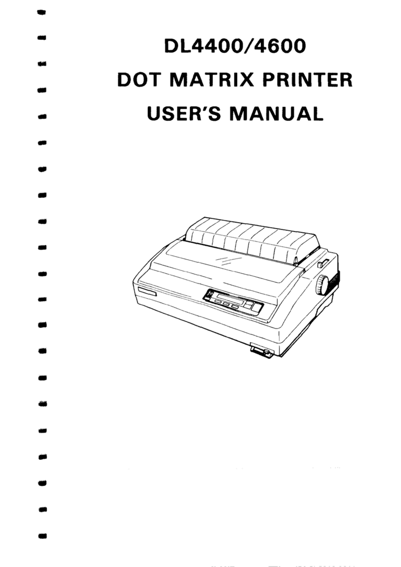
ENCAD CADJET 2 User manual

CADJET 2i
CADJET®2
Service Manual
Copyright 1995 ENCAD®,Inc. All rights reserved.
ENCAD is a registered trademark of ENCAD, Inc.
Trademark application for CADJET 2is pending.
HP-GL, HP-GL/2, and HP RTL are registered trademarks of Hewlett-
Packard Company.
AutoCAD is a registered trademark of AutoDesk, Inc.
Other trademarks and registered trademarks are the property of their
respective owners.
No part of this manual may be copied or distributed, transmitted,
transcribed, stored in a retrieval system, or translated in any human or
computing language, in any form or by any means, electronic,
mechanical, magnetic or otherwise, or disclosed to a third party without
the express written permission of ENCAD, Inc., 6059 Cornerstone
Court West, San Diego, CA 92121, U.S.A.

ii CADJET 2
FCC Statement (U.S.A)
The United States Federal Communications Commission
(47 CFR 15.105 and 15.27) has specified that the following notice be
brought to the attention of the users of the CADJET 2.
FEDERAL COMMUNICATIONS COMMISSION RADIO FREQUENCY
INTERFERENCE STATEMENT
This equipment has been tested and found to comply with the limits for
a Class B digital device, pursuant to part 15 of the FCC Rules. These
limits are designed to provide reasonable protection against harmful
interference in a residential installation. This equipment generates,
uses, and can radiate radio frequency energy and, if not installed and
used in accordance with the instructions, may cause harmful
interference to radio communications.
User Instructions:
If the equipment does cause harmful interference to radio or television
reception, which can be determined by turning the equipment off and
on, the user is encouraged to try to correct the interference by one of
the following measures:
lReorient or relocate the receiving antenna.
lIncrease the separation between the equipment and receiver.
lConnect the equipment into an outlet on a circuit different from
that to which the receiver is connected.
lConsult the dealer or an experienced radio/TV technician for
help.
Changes or modifications not expressly approved by ENCAD, Inc.
could void the user’s authority to operate the equipment.
Note: This product was FCC certified under test conditions that
included the use of shielded I/O cables and connectors
between system components. To be in compliance with FCC
regulations, the user must use shielded cables and
connectors and install them properly.

CADJET 2iii
VDE Statement
Hiermit wird bescheinigt, daß der CADJET 2in Übereinstimmung mit
den Bestimmungen der BMPT-AmstbIVfg 234/1991 funkentstört ist.
Der vorschriftsmäßige Betrieb mancher Geräte (z.B. Meßsender) kann
allergings gewissen Einschränkungen unterliegen. Beachten Sie
deshalb die Hinweise in der Bedienungsanleitung.
Dem Zentralamt für Zulassungen im Femmeldewesen wirde dan
Inverkehrbringen dieses Gerätes angezeigt und die Berechtigung zur
Überprüfung der Serie auf die Einhaltung der Bestimmungen
eingeräumt.
ENCAD, Inc. U.S.A

iv CADJET 2
Material Safety Data Sheet
CADJET 2ink is nonhazardous, requiring no special disposal
handling. It can be harmful if swallowed and should be kept away from
children.
To obtain a Material Safety Data Sheet, contact ENCAD, Inc. at:
6059 Cornerstone Court West
San Diego, CA 92121-3734
(619) 452-4350
International users should contact their local dealer or distributor.

CADJET 2v
PRINTING HISTORY
1st Edition September 18, 1995

CADJET 2vi
TABLE OF CONTENTS
QUICK OVERVIEW
CHAPTER 1 GENERAL INFORMATION............................................................... 1-1
CHAPTER 2 THEORY OF OPERATION............................................................... 2-1
CHAPTER 3 MAINTENANCE................................................................................ 3-1
CHAPTER 4 TROUBLESHOOTING...................................................................... 4-1
CHAPTER 5 DISASSEMBLY/ASSEMBLY ............................................................ 5-1
CHAPTER 6 CALIBRATION.................................................................................. 6-1
CHAPTER 7 REPLACEMENT PARTS LIST.......................................................... 7-1
APPENDIX A EMERGENCY FIRMWARE DOWNLOAD PROCEDURE ................A-1
APPENDIX B PRINTER FIRMWARE UPGRADE PROCEDURE...........................B-1
APPENDIX C FINAL ASSEMBLY DRAWINGS.......................................................C-1
APPENDIX D SCHEMATICS...................................................................................D-1

Table of Contents
CADJET 2vii
CHAPTER 1 GENERAL INFORMATION
Overview, Technical Support, media sizes and plot areas, general product
notes, plotter features and specifications, Line Length Accuracy and Skew
information, acronyms and abbreviations, and glossary.
1.0 Introduction........................................................................................................1-1
2.0 Overview............................................................................................................1-2
2.1 Related Publications ............................................................................1-2
2.2 Features of this Service Manual...........................................................1-3
2.2.1 Subject Headings.................................................................1-3
2.2.2 Figures and Tables..............................................................1-3
2.2.3 Manual Conventions............................................................1-4
3.0 ENCAD Technical Support & Service ...............................................................1-5
4.0 Media Sizes and Plotting Areas.........................................................................1-6
5.0 General Product Notes......................................................................................1-9
6.0 Plotter Features...............................................................................................1-10
7.0 Plotter Specifications.......................................................................................1-13
8.0 Line Length Accuracy......................................................................................1-14
9.0 Skew................................................................................................................1-15
10.0 Acronyms and Abbreviations...........................................................................1-17
11.0 Glossary..........................................................................................................1-18

Table of Contents
viii CADJET 2
CHAPTER 2 THEORY OF OPERATION
Mechanical overview and electrical circuitry theory with block diagram
visuals.
1.0 Introduction ....................................................................................................... 2-1
2.0 Mechanical Operation....................................................................................... 2-2
2.1 Media Axis Drive.................................................................................. 2-2
2.2 Carriage Axis Drive.............................................................................. 2-2
3.0 Electrical Operation........................................................................................... 2-3
3.1 Circuit Assemblies............................................................................... 2-3
3.1.1 Main Printed Circuit Board (MPCB)..................................... 2-3
3.1.2 Front Panel Circuit............................................................... 2-3
3.1.3 Carriage Printed Circuit Assembly (Carriage PCB).............. 2-4
3.2 Block Diagram ..................................................................................... 2-5
3.3 Power Supply....................................................................................... 2-6
3.4 Microprocessor.................................................................................... 2-7
3.5 Start-up Sequence............................................................................... 2-8
3.6 Memory................................................................................................ 2-9
3.7 Flash EPROM.................................................................................... 2-10
3.8 RAM................................................................................................... 2-11
3.9 EEPROM........................................................................................... 2-11
3.10 Gate Array ......................................................................................... 2-12
3.11 Stepper Motor.................................................................................... 2-13
3.12 Servo Motor....................................................................................... 2-15
3.13 Parallel and Serial Ports.................................................................... 2-16
3.14 Keypad/Display.................................................................................. 2-17
3.15 Carriage Circuits................................................................................ 2-18
3.16 LED’s, Beeper, and Fan .................................................................... 2-19
3.17 Dot Firing Sequence.......................................................................... 2-19
3.18 Schematic Diagrams.......................................................................... 2-19

Table of Contents
CADJET 2ix
CHAPTER 3 MAINTENANCE
Maintenance of Unit, Slide Shaft, Service Station, Encoder Strip,
Cartridges, and Rollers.
1.0 Introduction........................................................................................................3-1
2.0 External Cleaning..............................................................................................3-2
3.0 Slide Shaft Maintenance ...................................................................................3-3
4.0 Service Station Maintenance.............................................................................3-5
5.0 Encoder Strip Maintenance...............................................................................3-6
6.0 Ink Cartridge Maintenance ................................................................................3-7
6.1 Initial Installation of Cartridges.............................................................3-7
6.2 Cleaning Cartridges .............................................................................3-9
6.3 Other Causes of Misfiring...................................................................3-11
6.4 Storage of Cartridges During Extended Periods of Inoperation.........3-12
6.5 Refilled Cartridges..............................................................................3-12
7.0 Upper and Lower Rollers.................................................................................3-13

Table of Contents
xCADJET 2
CHAPTER 4 TROUBLESHOOTING
Chart of problems and solutions with detailed action steps and cross
reference information. Service Menu information. Keypad functions and
messages. Plotter initialization sequence. Plotter error message
descriptions. Operation problems.
1.0 Introduction ....................................................................................................... 4-1
2.0 Decision Logic Tables....................................................................................... 4-2
2.1 Procedure for Using Decision Logic Tables......................................... 4-2
2.2 Decision Logic Tables.......................................................................... 4-3
3.0 Service Menu.................................................................................................... 4-8
4.0 Service Menu Description ................................................................................. 4-9
4.1 Service Information............................................................................ 4-10
4.1.1 Information Display Settings.............................................. 4-10
4.1.2 Information Print Settings .................................................. 4-13
4.2 Service Diagnostics ........................................................................... 4-14
4.3 Service Calibration............................................................................. 4-17
5.0 LED Keys........................................................................................................ 4-18
6.0 LCD Keypad.................................................................................................... 4-19
7.0 Keypad Messages........................................................................................... 4-20
7.1 Plot Received..................................................................................... 4-20
7.2 Drying Plot......................................................................................... 4-20
7.3 Insert Media....................................................................................... 4-20
7.4 Memory Full....................................................................................... 4-20
7.5 RAM OK............................................................................................. 4-21
7.6 Checksum Error................................................................................. 4-21
7.7 Plotter Error ....................................................................................... 4-21
7.8 Ready to Replot................................................................................. 4-21
8.0 Initialization Sequence.................................................................................... 4-22
9.0 RS-422/RS-232 Error Messages..................................................................... 4-23
10.0 RAM Error....................................................................................................... 4-24

Table of Contents
CADJET 2xi
CHAPTER 4 TROUBLESHOOTING (continued)
11.0 Operation Problems ........................................................................................4-25
11.1 Plotter Does Not Turn On...................................................................4-25
11.2 Plotter Slow to Initialize......................................................................4-26
11.3 Plotter Will Not Plot............................................................................4-27
11.3.1 Parallel Interface and Serial Interface Tests......................4-29
11.4 No Movement in the Carriage Axis.....................................................4-31
11.5 Media Problems.................................................................................4-34
11.5.1 Cut Sheet Media Won’t Load.............................................4-34
11.5.2 Media Feeds Out of Plotter When Plot is Completed ........4-36
11.5.3 Media Skews or Ripples.....................................................4-36
11.5.4 Loaded Media Not Detected, Media Size Not Detected,
or Plotter Has Incorrect Plot Area ......................................4-37
11.5.5 Keypad Display Shows LOAD MEDIA Message When
Rollfeed Media is Loaded ..................................................4-38
11.5.6 Loud Grinding Noise When Media Loads..........................4-39
11.6 Media Cutting Problems.....................................................................4-41
11.7 Ink Cartridge Problems ......................................................................4-42
11.7.1 Dried Up Cartridge.............................................................4-43
11.7.2 Determining Ink Level........................................................4-44
11.8 PRIME Plot ........................................................................................4-45
11.9 Tri-Color Cartridge Failure Test Procedure........................................4-46
11.10 Black Cartridge Failure Test Procedure.............................................4-47
11.10.1 Running the Cartridge Diagnostic Test..............................4-48
11.10.2 Interpreting the Cartridge Diagnostic Test .........................4-50
11.10.3 Black Cartridge Flex Test...................................................4-51
11.11 Memory Full .......................................................................................4-55
11.12 Plotter Hesitates During Plotting........................................................4-56
11.13 Plot Appearance is not as Expected..................................................4-56
11.14 Plots are Cut Off. ...............................................................................4-57

Table of Contents
xii CADJET 2
CHAPTER 4 TROUBLESHOOTING (continued)
11.15 Plotter is Noisy................................................................................... 4-58
11.16 User Parameters Not Saved When Power Is Cycled......................... 4-58
11.17 Plotter Carriage Moves Erratically...................................................... 4-59
11.18 Media Movement Erratic.................................................................... 4-61
11.19 LCD or LED Key(s) Inoperative ......................................................... 4-62
11.20 Front Keypad Display Inoperative...................................................... 4-64

Table of Contents
CADJET 2xiii
CHAPTER 5 DISASSEMBLY/ASSEMBLY
Detailed procedures for removing and installing field replaceable parts
and assemblies.
1.0 Introduction........................................................................................................5-1
2.0 Tools and Equipment Required.........................................................................5-4
3.0 Stand.................................................................................................................5-7
3.1 Removing the Plotter from the Stand...................................................5-7
3.2 Replacing the Plotter on the Stand ......................................................5-9
3.3 Alternate Method for Securing Carriage Assembly and Fixed
Blade..................................................................................................5-10
4.0 Right Cover Assembly, SIMMS, and MPCB....................................................5-11
4.1 Removing the Right Cover Assembly.................................................5-11
4.2 Removing the MPCB Connectors......................................................5-13
4.3 MPCB.................................................................................................5-15
4.3.1 Removing the MPCB..........................................................5-15
4.3.2 Reinstalling the MPCB.......................................................5-16
4.4 Reinstalling the MPCB Connectors....................................................5-17
4.5 Extra Memory (SIMM)........................................................................5-18
4.5.1 Extra Memory (SIMM) Removal.........................................5-18
4.5.2 Extra Memory (SIMM) Installation......................................5-19
4.6 Reinstalling the Right Cover Assembly..............................................5-20
5.0 Servo Motor.....................................................................................................5-21
5.1 Removing the Servo Motor ................................................................5-21
5.2 Replacing the Servo Motor.................................................................5-24
6.0 Display Assembly............................................................................................5-25
6.1 Removing the Display Assembly........................................................5-25
6.2 Reinstalling the Display Assembly.....................................................5-26
7.0 Service Station Assembly................................................................................5-27
7.1 Removing the Service Station Assembly ...........................................5-27
7.2 Reinstalling the Service Station Assembly.........................................5-29

Table of Contents
xiv CADJET 2
CHAPTER 5 DISASSEMBLY/ASSEMBLY (continued)
8.0 Left Cover Assembly, Left Side Plate, Carriage Assembly, Trailing Cable,
and Carriage Belt............................................................................................ 5-30
8.1 Removing the Left Cover Assembly and Left Side Plate................... 5-30
8.2 Removing the Carriage Assembly ..................................................... 5-32
8.3 Reinstalling the Carriage Assembly................................................... 5-35
8.4 Reinstalling the Left Side Plate and Left Cover Assembly................. 5-40
8.5 Removing the Trailing Cable.............................................................. 5-41
8.6 Reinstalling the Trailing Cable........................................................... 5-43
8.7 Removing the Carriage Belt from Carriage Assembly ....................... 5-46
8.8 Installing the Carriage Belt on Carriage Assembly............................. 5-47
9.0 Power Supply and ON/OFF Switch................................................................. 5-48
9.1 Removing the Power Supply and ON/OFF Switch............................. 5-48
9.2 Installing the Power Supply and ON/OFF Switch............................... 5-49
10.0 Stabilizer Bracket and Encoder Strip............................................................... 5-50
10.1 Removing the Stabilizer Bracket........................................................ 5-51
10.2 Reinstalling the Stabilizer Bracket ..................................................... 5-52
11.0 Lower Drive Assembly, Fan Assembly, and Stepper Motor Assembly
(Inner Platen Parts)......................................................................................... 5-54
11.1 Disassembly of Plotter Before Removing the Inner Platen Parts....... 5-55
11.2 Removing the Inner Platen Parts....................................................... 5-57
11.3 Stepper Motor.................................................................................... 5-61
11.3.1 Removing the Stepper Motor............................................. 5-61
11.3.2 Reinstalling the Stepper Motor .......................................... 5-63
11.4 Reinstalling the Inner Platen Parts..................................................... 5-64
11.5 Reassembly of Plotter After Reinstalling the Inner Platen Parts........ 5-67
12.0 Fixed Blade..................................................................................................... 5-70
12.1 Removing the Fixed Blade................................................................. 5-70
12.2 Reinstalling the Fixed Blade .............................................................. 5-71

Table of Contents
CADJET 2xv
CHAPTER 5 DISASSEMBLY/ASSEMBLY (continued)
13.0 Cutter Wheel...................................................................................................5-72
13.1 Removing the Cutter Wheel...............................................................5-72
13.2 Replacement of Cutter Wheel............................................................5-74
14.0 Upper Roller Supports.....................................................................................5-75
14.1 Removing the Upper Roller Supports ................................................5-76
14.2 Installing the Upper Roller Supports ..................................................5-81

Table of Contents
xvi CADJET 2
CHAPTER 6 CALIBRATION
Procedures to mechanically and electrically align the plotter following
repairs, or when plotter performance has been affected.
1.0 Introduction ....................................................................................................... 6-1
2.0 Required Supplies and Tools............................................................................ 6-2
3.0 Required Documentation and Files................................................................... 6-4
4.0 Downloading Files From the BBS ..................................................................... 6-5
5.0 Numbering Sequence of Upper Roller Supports............................................... 6-7
6.0 Adjustments Prior to Calibration........................................................................ 6-8
6.1 Slide Shaft Profile Adjustment............................................................. 6-9
6.2 Cartridge Head Height Adjustment.................................................... 6-12
6.2.1 Gauge Setup Procedure.................................................... 6-12
6.2.2 Cartridge Head Height Adjusting Procedure...................... 6-17
6.2.3 Verify Head Height Values................................................. 6-18
6.3 Encoder Strip Location/Visual Check................................................. 6-19
6.4 Idler Pulley and Belt Position Check.................................................. 6-20
6.5 Power Up and ROM Verification Test................................................ 6-21
6.5.1 Functional Test.................................................................. 6-21
6.5.2 Adjustment of the Paper Sensor Potentiometer ................ 6-23
7.0 Paper Skew Setup .......................................................................................... 6-27
8.0 Paper Skew Adjustment.................................................................................. 6-28
8.1 Paper Skew Adjustment Sequence ................................................... 6-29
8.2 Mounting Screw Information.............................................................. 6-30
8.3 Other Functional Requirements......................................................... 6-33
8.4 Adjustment of Upper Roller Supports................................................ 6-34
8.4.1 Visual Verification.............................................................. 6-34
8.4.2 Observation of Paper Skew at Rear Media Alignment
Mark................................................................................... 6-35
8.4.3 Observation of Paper Skew at Front Media Alignment
Mark................................................................................... 6-37
8.4.4 Adjustment of the Mounting Screws.................................. 6-38

Table of Contents
CADJET 2xvii
CHAPTER 6 CALIBRATION (continued)
9.0 Plotting PRIME Pattern....................................................................................6-39
10.0 XY Calibration..................................................................................................6-43
10.1 Calibrating the Y-Axis (Carriage Axis or Horizontal Axis
Calibration).........................................................................................6-44
10.2 Calibrating the X-Axis (Paper Axis or Vertical Axis Calibration).........6-46
11.0 Deadband Calibration......................................................................................6-47
11.1 Slow Deadband Calibration................................................................6-48
11.2 Fast Deadband (Height Calibration)...................................................6-50
11.2.1 Adjusting Fast Deadband; Vertical Lines (All) and
Vertical Lines (One)...........................................................6-51
12.0 Cartridge Calibration -Horizontal and Vertical ................................................6-53
12.1 Adjusting the Horizontal Head-to-Head Calibration............................6-55
12.2 Adjusting the Vertical Head-to-Head Calibration................................6-56
13.0 Color Deadband Calibration............................................................................6-57
13.1 Adjusting the Color Deadband Value.................................................6-58
14.0 Line Quality Plot (Computer) Test...................................................................6-60

Table of Contents
xviii CADJET 2
CHAPTER 7 REPLACEMENT PARTS LIST
A complete listing (numerical, alphabetical, and illustrated alphabetical) of
all field replaceable parts and assemblies for the CADJET 2Color Inkjet
Plotters.
1.0 Introduction ....................................................................................................... 7-1
2.0 Numerical Listing............................................................................................... 7-2
2.1 Parts Used in both D-Size and E-Size (Numerical).............................. 7-2
2.2 D-Size Unique Parts (Numerical)......................................................... 7-4
2.3 E-Size Unique Parts (Numerical)......................................................... 7-5
3.0 Alphabetical Listing........................................................................................... 7-6
3.1 Parts Used in both D-Size and E-Size (Alphabetical).......................... 7-6
3.2 D-Size Unique Parts (Alphabetical) ..................................................... 7-8
3.3 E-Size Unique Parts (Alphabetical)...................................................... 7-9
4.0 Alphabetical Listing with Drawings.................................................................. 7-10
4.1 Drawings -Parts Used in both D-Size and E-Size............................. 7-10
4.2 Drawings -D-Size Unique Parts ........................................................ 7-26
4.3 Drawings -E-Size Unique Parts......................................................... 7-30

Table of Contents
CADJET 2xix
APPENDICES
APPENDIX A EMERGENCY FIRMWARE DOWNLOAD PROCEDURE
Procedure for downloading firmware to a CADJET 2Color Inkjet Plotter
which has a blank or corrupt Flash EPROM.
Emergency Firmware Download Procedure.................................................................A-1
APPENDIX B PRINTER FIRMWARE UPGRADE PROCEDURE
Procedure for upgrading a CADJET 2Color Inkjet Plotter to the newest
version of firmware (Flash EPROM is not blank or corrupt).
Printer Firmware Upgrade Procedure ..........................................................................B-1
APPENDIX C FINAL ASSEMBLY DRAWINGS
CADJET 2Color Inkjet Plotters (D-Size and E-Size) Final Assembly
Drawings with Callouts.
CADJET 2D-Size Final Assembly Callouts................................................................ C-2
CADJET 2E-Size Final Assembly Callouts................................................................ C-4
APPENDIX D SCHEMATICS
Schematics for the CADJET 2Color Inkjet Plotters Boards.
Main PCB Assembly ............................................................................................ 9 pages
Keypad PCB Assembly..........................................................................................1 page
Carriage PCB Assembly....................................................................................... 2 pages
Flex Circuit............................................................................................................. 1 page

Table of Contents
xx CADJET 2
FIGURES
CHAPTER 1 GENERAL INFORMATION
Number Title Page
Figure 1.1 Front View -- Cover Closed................................................................ 1-10
Figure 1.2 Front View -- Cover Open.................................................................. 1-11
Figure 1.3 Back View.......................................................................................... 1-12
Figure 1.4 Line Length Accuracy........................................................................ 1-14
Figure 1.5 Skew.................................................................................................. 1-15
CHAPTER 2 THEORY OF OPERATION
Number Title Page
Figure 2.1 Major Functional Areas of the Plotter .................................................. 2-5
Figure 2.2 Gate Array ......................................................................................... 2-12
Figure 2.3 Stepper Motor.................................................................................... 2-14
Figure 2.4 Servo Motor....................................................................................... 2-15
Figure 2.5 Parallel and Serial Ports.................................................................... 2-16
Figure 2.6 Keypad Display.................................................................................. 2-17
Figure 2.7 Carriage Circuits................................................................................ 2-18
CHAPTER 4 TROUBLESHOOTING
Number Title Page
Figure4.1 LED Keys........................................................................................... 4-18
Figure 4.2 LCD Keypad ...................................................................................... 4-19
Figure 4.3 Parallel and Serial Loop Back Tests.................................................. 4-30
Figure 4.4 Tri-Color Cartridge Flex ..................................................................... 4-46
Figure 4.5 Sample of Black Cartridge Diagnostics Test...................................... 4-50
Figure 4.6 Black Cartridge Failure Test Setups.................................................. 4-51
Figure4.7 Black Cartridge Flex Dimple Pattern.................................................. 4-53
Table of contents
Other ENCAD Printer manuals

ENCAD
ENCAD VinylJet 36 User manual

ENCAD
ENCAD CADJET User manual
ENCAD
ENCAD CADJET 3D User manual

ENCAD
ENCAD NovaCut 24 User manual
ENCAD
ENCAD NovaJet 4 User manual
ENCAD
ENCAD NovaJet PRO 600e User manual

ENCAD
ENCAD CADJET 3D User manual

ENCAD
ENCAD Croma 24 User manual

ENCAD
ENCAD CROMA24 User manual
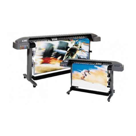
ENCAD
ENCAD 60e User manual

ENCAD
ENCAD ENCAD T200+ User manual

ENCAD
ENCAD NovaJet 800 Series User manual

ENCAD
ENCAD NovaJet 500 Manual
ENCAD
ENCAD Encad NovaJet 1000i User manual

ENCAD
ENCAD NovaJet 630 User manual

ENCAD
ENCAD NovaJet 880 User manual

ENCAD
ENCAD CROMA24 User manual

ENCAD
ENCAD VinylJet 36 User manual
ENCAD
ENCAD 215319-1 User manual

ENCAD
ENCAD NovaJet PRO 600e User manual

