ENCAD CADJET User manual

CADJET®3D
COLOR INKJET
PRINTER
SERVICE MANUAL
PartNumber215508-00
®

iv
CadJet3DServiceManual
Copyright © 1999 ENCAD®, Inc. All rights reserved.
ENCAD®andCadJet®are trademarksofENCAD, Inc.
Othertrademarks andregisteredtrademarks arethe
propertyoftheir respectiveowners.
Except as provided below, no part of this manual may be
copiedor distributed, transmitted,transcribed, stored in
a retrieval system, or translated in any human or comput-
ing language, in any form or by any means, electronic,
mechanical, magnetic or otherwise, or disclosed to a
third party without the express written permission of
ENCAD, Inc.,6059 CornerstoneCourt West,San Diego,
CA 92121, U.S.A.
Certainmanuals developed byENCAD areinan elec-
tronicformat tobe distributed onCDs orover the
internet. Theregistered userof anENCAD product
whose manual is distributed in this fashion may print one
copy for their personal use only.
Printing history
1st Edition RevA Feburary2000

v
CadJet3DServiceManual
FCC Statement (U.S.A.)
TheUnited StatesFederal CommunicationsCommision hasspecified that
thefollowing noticebe brought to the attentionof theusers ofthe CADJET
3D printer.
FEDERALCOMMUNICATIONSCOMMISIONRADIOANDTELEVISION
INTERFERENCEFORCLASS BDEVICE
This equipment has been tested and found to comply with the limits for a
class B digital device, pursuant to part 15 of the FCC Rules. These limits
aredesignedto provide reasonableprotectionagainstharmful interference
in a residential installation. This equipment generates, uses, and can
radiateradio frequencyenergy and,if notinstalled andused inaccordance
withthe instructions,may cause harmful interference toradio communica-
tions.
User Instructions:
Ifthe equipment doescause harmfulinterference to radioor television
reception,which canbe determinedby turningthe equipmentoff andon,
the user is encouraged to try to correct the interference by one of the
followingmeasures:
•Reorientorrelocate thereceivingantenna.
•Increasetheseparation betweentheequipmentand receiver.
•Connectthe equipmentinto an outlet on acircuit differentfrom
that to which the receiver is connected.
•Consultthe dealeroran experiencedradio/TV technicianfor
help.
Changesor modificationsnotexpressly approvedby ENCAD, Inc. could
voidthe user’sauthority tooperate theequipment.

vi
CadJet3DServiceManual
VDE Statement
Hiermit wirdbescheinigt, daßder CADJET 3D in Übereinstimmungmit
denBestimmungen derBMPT-AmstbIVfg 234/1991funkentstört ist. Der
vorschriftsmäßigeBetrieb mancherGeräte(z.B. Meßsender)kann
allerdingsgewissen Einschränkungenunterliegen. BeachtenSie deshalb
dieHinweisein derBedienungsanleitung.
DemZentralamtfürZulassungen im Fernmeldewesenwürdedan
InverkehrbringendiesesGerätes angezeigt unddieBerechtigung zur
ÜberprüfungderSerie auf dieEinhaltungder Bestimmungeneingeräumt.
ENCAD, Inc. U.S.A

vii
CadJet3DServiceManual
Material Safety Data Sheet
ENCAD QIS(Quality ImagingSupplies) inkisnonhazardous, requiringno
special disposal handling. It can be harmful if swallowed and should be
keptaway fromchildren.
To obtain a Material Safety Data Sheet, contact ENCAD, Inc. at:
6059 Cornerstone Court West
San Diego, CA 92121-3734
(619) 452-4350
International users should contact their local dealer or distributor.

viii
CadJet3DServiceManual
WARRANTY OR DAMAGE CLAIMS
United States
ENCAD®, Inc., warrants its printers ("PRODUCT") to be free from defects in workmanship
and materials for a period of one year from the date of purchase. In order to submit a
Warranty claim, please contact the ENCAD Help Desk at (619) 452-4350.
ENCAD reserves the right to make changes or improvements to Products, without incurring
any obligation to similarly alter Products previously purchased.
Buyer's sole and exclusive rights pursuant to this Warranty shall be for the repair or
replacement of defective Product. ENCAD specifically disclaims any and all other warran-
ties, expressed or implied, including but not limited to, implied warranties of merchantability
and fitness for a particular purpose. In no event shall ENCAD be liable for any loss of
profit or other commercial damages, special, incidental or consequential damages, or any
otherdamages orclaims, whatsoever.
This Warranty gives Buyer specific legal rights, and Buyer may also have other rights that
varyfrom state tostate.
This Warranty applies only to printers purchased from ENCAD, or authorized ENCAD
distributors or dealers. The intent of this Warranty is to repair or replace defective Prod-
ucts subjected to normal wear and tear, when operated according to ENCAD instructions.
This Warranty does not cover damage to the Product resulting from the following:
• Accident or negligence.
• Unauthorized modification of the Product.
• Adverse environmental conditions.
• Service of the Product by other than an ENCAD authorized service provider.
• Unauthorized or improper use, including but not limited to:
– Use in applications for which the Product was not designed.
– Using cartridges or ink other than those supplied by ENCAD or authorized
ENCAD resellers.
– Using media other than that supplied by ENCAD or authorized ENCAD
resellers.
– Lubricating any part of the printer.
Internationally: Contact your dealer or distributor for warranty information.

ix
CadJet3DServiceManual
Table of Contents
Chapter 1 General Description ............................................................ 1-1
Introduction...............................................................................................................1-1
Overview ...................................................................................................................1-3
RelatedPublications ..........................................................................................1-3
ElectrostaticDischarge (ESD)Sensitivity .................................................................1-3
Warnings,Cautions andNotes .................................................................................1-4
PrinterSpecifications................................................................................................1-5
Contentsof thisService Manual................................................................................1-6
TechnicalSupport .....................................................................................................1-8
Chapter 2 Theory of Operation............................................................ 2-1
Introduction...............................................................................................................2-1
CadJet3DPrinter General BlockDiagram ................................................................2-1
Paper(Media)Axis Drive ..........................................................................................2-3
TheCarriageAxisDrive.............................................................................................2-4
MainPrinted CircuitBoard (MPCB)...........................................................................2-5
Microprocessor ..................................................................................................2-6
GateArray .........................................................................................................2-6
MemoryCircuits.................................................................................................2-7
Flash EEPROM ...........................................................................................2-7
DRAM..........................................................................................................2-8
SerialEEPROM...........................................................................................2-9
StepperMotorController.....................................................................................2-9
ServoMotorController ...................................................................................... 2-11
Interface Circuits:Serial& Parallel ................................................................... 2-13
Carriage AssemblyCircuits .................................................................................... 2-14
ControlPanel.......................................................................................................... 2-15
PowerSupply .........................................................................................................2-16
BeeperandFans .................................................................................................... 2-16
Chapter 3 Maintenance ........................................................................ 3-1
Introduction...............................................................................................................3-1
ScheduledMaintenance ...........................................................................................3-1
CleaningProcedures ..........................................................................................3-2
ExternalCleaning.........................................................................................3-2
SlideShaftCleaning.....................................................................................3-2

x
CadJet3DServiceManual
ServiceStationCleaning ..............................................................................3-3
LinearEncoderStrip Cleaning......................................................................3-4
CartridgeDimplesCleaning..........................................................................3-5
FlexCable Contact Cleaning........................................................................3-6
Cleanand InspectStepperMotor Gears.......................................................3-7
Cleanand InspectMPCB.............................................................................3-7
Cleanand Inspect CarriageAssembly .........................................................3-8
ReseatConnectorson MPCBandCarriage Board..............................................3-8
ReplaceCarriageBushings .............................................................................. 3-10
ServoMotor WindingResistanceCheck ................................................................. 3-11
Stepper Motor WindingResistance Check.............................................................. 3-12
Banding:HardwarevsSoftware............................................................................... 3-13
CommonBandingCauses ......................................................................... 3-14
Alignments/Adjustments.........................................................................................3-16
Slide Shaft ProfileAdjustment .......................................................................... 3-16
HeadHeightAlignment Procedure.................................................................... 3-19
ColorCalibration............................................................................................... 3-23
DeadbandAlignments ......................................................................................3-26
ColorDeadbandAlignment......................................................................... 3-30
Paper Axis Calibration...................................................................................... 3-32
Diagnostics Menu................................................................................................... 3-34
Limited Access Menu .............................................................................................3-37
FirmwareDownload/UpgradingforthePC ...............................................................3-38
FirmwareDownload/UpgradingfortheMAC ............................................................ 3-39
InternalCablingand SignalFlowDiagrams ............................................................. 3-41
Chapter 4 Troubleshooting.................................................................. 4-1
Introduction...............................................................................................................4-1
NoPower ...........................................................................................................4-1
InitializationFailure.............................................................................................4-2
MediaDoesNot Move ........................................................................................4-2
InternalERROR“CarriageAxis Failure” ..............................................................4-3
InternalERROR“EncoderSensor Failure” ..........................................................4-5
Table of Contents (cont)
Chapter 3 Maintenance (cont)

xi
CadJet3DServiceManual
InternalERROR“PaperSensorFailure”..............................................................4-5
InternalERROR“Auto-SensorFailure”................................................................4-6
InternalERROR“MPCBFailure”.........................................................................4-6
UnrecognizedCartridgesError............................................................................4-6
ImageSkewsor Moves ......................................................................................4-7
Does Not Print....................................................................................................4-7
InkCartridgeMisfiring .........................................................................................4-7
PaperSkewing ...................................................................................................4-9
PrinterOutput isBanding(Horizontal) ................................................................4-9
PrinterOutput isBanding (Vertical) .................................................................. 4-11
PrinterOutput isBanding (Horizontallyand Vertically)...................................... 4-11
KeypadLocked-Up or NotFunctioning Properly ............................................... 4-11
NoisyOperation ...............................................................................................4-12
LineQualityDegraded ......................................................................................4-13
FanDoes NotPower Up................................................................................... 4-14
InitializationTroubleshooting ...................................................................................4-16
Chapter 5 Assembly\Disassembly ...................................................... 5-1
Introduction...............................................................................................................5-1
RemovetheLeft,Top, and RightCovers ....................................................................5-2
Installthe Left,Top,and Right Covers .......................................................................5-5
RemovetheKeypad, Display,andDisplayPowerConverter......................................5-6
Installthe Keypad,Display,and DisplayPower Converter.........................................5-8
RemoveMemory(SIMM) ..........................................................................................5-9
Install Memory (SIMM)............................................................................................ 5-10
Remove theMPCB(Main PrintedCircuitBoard) ..................................................... 5-10
Install the MPCB ....................................................................................................5-13
Remove PowerSupply, CoolingFan, andACEntry Module .................................... 5-14
Install the Power Supply, Cooling Fan, and AC Entry Module ................................. 5-16
RemoveServoMotor ...............................................................................................5-17
InstallServoMotor ..................................................................................................5-19
RemovetheInk DeliverySystem............................................................................. 5-20
Installthe Ink DeliverySystem................................................................................ 5-23
Table of Contents (cont)
Chapter 4 Troubleshooting (cont)

xii
CadJet3DServiceManual
Remove theCarriageAssembly,Carriage Belt,andthe FrameTensioner................ 5-23
Installthe CarriageAssembly, CarriageBelt, and theFrame Tensioner..................5-26
RemovetheCarriagePCB ......................................................................................5-28
Install theCarriagePCB ......................................................................................... 5-30
Removethe PaperSensororthe EncoderSensor .................................................. 5-31
Install the PaperSensor or the EncoderSensor...................................................... 5-32
ReplacingtheCarriage Bushings ............................................................................ 5-34
RemovetheServiceStation .................................................................................... 5-35
Install the ServiceStation ....................................................................................... 5-36
Removethe TrailingCableAssembly ...................................................................... 5-36
Install theTrailingCable Assembly ......................................................................... 5-37
Remove the StabilizerBracket andEncoder Strip ................................................... 5-38
Install the Stabilizer Bracket and Encoder Strip ......................................................5-39
Removethe Y-ArmAssembly, PinchRollers, SlideShaft, and Auto-Load Sensor... 5-40
Install the Y-Arm Assembly, Pinch Rollers, Slide Shaft, and Auto-Load Sensor ......5-42
Remove theLower RollerAssembly, StepperMotor andVacuumFan..................... 5-44
Installthe Lower RollerAssembly, StepperMotor and Vacuum Fan........................ 5-47
Chapter 6 Parts List.............................................................................. 6-1
Index...............................................................................................Index-1
Table of Contents (cont)
Chapter 5 Assembly/Disassembly (cont)

xiii
CadJet3DServiceManual
List of Illustrations
Figure Page
Chapter 1 General Description
1-1. CadJet3D Inkjet Printer ..................................................................................1-1
Chapter 2 Theory of Operation
2-1. GeneralBlockDiagram ...................................................................................2-2
2-2. Paper(Media)Axis Drive.................................................................................2-3
2-3. CarriageAxisDrive..........................................................................................2-4
2-4. MainPrinted CircuitBoard ..............................................................................2-5
2-5. GateArray ......................................................................................................2-6
2-6. StepperMotorController .................................................................................2-9
2-7. ServoMotorController................................................................................... 2-11
2-8. QuadratureSignalGeneration .......................................................................2-12
2-9. InterfaceCircuits ........................................................................................... 2-13
2-10. Carrier AssemblyCircuits ............................................................................. 2-14
2-11. MainMenu .................................................................................................... 2-15
Chapter 3 Maintenance
3-1. EncoderStripCleaning ...................................................................................3-5
3-2. CartridgeDimpleRegion..................................................................................3-5
3-3. FlexCable Contacts .......................................................................................3-6
3-4. MainPCB ConnectionLocations.....................................................................3-9
3-5. CarriagePCBConnection Locations ...............................................................3-9
3-6. RibbonConnector LockingMechanism ......................................................... 3-10
3-7. ServoMotor................................................................................................... 3-11
3-8. StepperMotor ...............................................................................................3-12
3-9. Examples ofBanding .................................................................................... 3-13
3-10. Dial Gauge Micrometer Assembly................................................................. 3-17
3-11. Measurement PositionsforSlide Shaft.......................................................... 3-18
3-12. SlideShaft ProfileAdjustment....................................................................... 3-19
3-13. CarrierHeadHeightTolerance ....................................................................... 3-20
3-14. Setting UpTools fromHeight GaugeKit ........................................................ 3-20
3-15. Zeroing theMicrometerGauge ...................................................................... 3-21

xiv
CadJet3DServiceManual
List of Illustrations (cont)
Figure Page
Chapter 3 Maintenance (cont)
3-16. TestCartridgeInstalled.................................................................................. 3-21
3-17. ColorCalibration............................................................................................3-24
3-18. Utility Menu................................................................................................... 3-25
3-19. ColorCalibMenu........................................................................................... 3-25
3-20. CyanVertical OptionsMenu.......................................................................... 3-26
3-21. DeadbandSlow/Fast ..................................................................................... 3-27
3-22. ServiceMenu ................................................................................................3-28
3-23. Calibration(Deadband)Menu ........................................................................3-29
3-24. CalibrationMenu ........................................................................................... 3-30
3-25. ColorDbMenu .............................................................................................. 3-31
3-26. Paper Axis Test ............................................................................................ 3-33
3-27. Diagnostics Menu .........................................................................................3-34
3-28. Accessory Menu........................................................................................... 3-35
3-29. NVRAM Clear and ClockReset Menu ........................................................... 3-37
3-30. MPCBConnectionsDiagram......................................................................... 3-42
3-31. CarriagePCBConnectionsDiagram.............................................................. 3-43
Chapter 4 Troubleshooting
4-1. CarriageBoard LEDD2andD5 Locations..................................................... 4-17
Chapter 5 Assembly/Disassembly
5-1. Right Cover Assembly Removal/Installation .....................................................5-3
5-2. LeftCoverAssemblyRemoval/Installation .......................................................5-4
5-3. KeypadandDisplay Removal/Installation ........................................................5-7
5-4. KeypadGroundingConnection ........................................................................5-8
5-5. Memory(SIMM)Removal/Installation ..............................................................5-9
5-6. MPCBRemoval............................................................................................. 5-12

xv
CadJet3DServiceManual
List of Illustrations (cont)
Figure Page
Chapter 5 Assembly/Disassembly (cont)
5-7. PowerSupplyRemoval .................................................................................5-15
5-8. CoolingFan/ACEntry Module Removal......................................................... 5-16
5-9. Slacken CarriageBelt ................................................................................... 5-18
5-10. ElectronicsCover Removal ............................................................................ 5-21
5-11. DisconnectInk Delivery SystemLink ............................................................ 5-22
5-12. StrainReliefRemoval/Installation .................................................................. 5-24
5-13. Frame Tensioner ........................................................................................... 5-25
5-14. CarriageBelt Clamp ......................................................................................5-25
5-15. CarriagePCBRemoval/Installation ................................................................ 5-29
5-16. Paper andEncoderSensorRemoval ............................................................. 5-31
5-17. PaperandEncoder SensorInstallation.......................................................... 5-32
5-18. CarriageBushingRemoval ............................................................................ 5-34
5-19. Carriage Bushing Installation ......................................................................... 5-34
5-20. ServiceStationRemoval................................................................................5-35
5-21. StabilizerBracket Installation/Removal.......................................................... 5-38
5-22. Y-ArmInstallation/Removal ........................................................................... 5-41
5-23. Pinch Roller .................................................................................................. 5-41
5-24. Inner Platen Assembly/Disassembly............................................................. 5-45
5-25. StepperMotorRemoval/Installation ............................................................... 5-47
5-26. Inside Platen, RightSide............................................................................... 5-49
Chapter 6 Parts List
6-1. LeftSide PartsBreakdown..............................................................................6-3
6-2. PlatenandAbove PartsBreakdown ................................................................6-5
6-3. RightSide PartsBreakdown ...........................................................................6-7
6-4. InnerPlatenParts Breakdown .........................................................................6-9
6-5. CarriageAssembly Parts Breakdown ............................................................ 6-11

xvi
CadJet3DServiceManual
List of Tables
Table Page
Chapter 1 General Description
Chapter 2 Theory of Operation
Chapter 3 Maintenance
Chapter 4 Troubleshooting
4-1. TroubleshootingTable......................................................................................4-1
Chapter 5 Assembly/Disassembly
Chapter 6 Parts List
1
1-1
GENERAL
DESCRIPTION
GeneralDescription
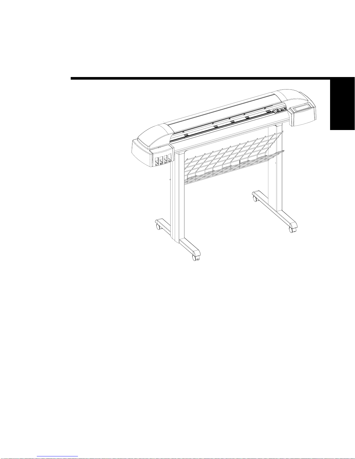
Figure 1-1. CadJet 3D Inkjet Printer.
Introduction
Thismanual providesservice informationfor the ENCAD®, Inc. 36
inchCadJet 3D Color InkjetPrinters.
Itiswritten forservicepersonnel whopossessanalog anddigital
circuitryexperience. Chapter 2,Theory of Operation,should be read
andthoroughlyunderstoodbeforetroubleshooting/calibratingthe
printers.
Theprinters supportbothpre-cut androll media. Mediasize is auto-
maticallydetermined andhardcliplimits areset accordingly. Pre-cut

1-2 GeneralDescription
CadJet3DServiceManual
mediauses differentmaximum plotting areasthan rollmedia. See the
PrinterSpecifications intheUser Guidefor moredetailson themedia
sizeprintablearea.
BothRS-422serialand Centronics parallelconnectionsareprovidedto
interfacewith thehostcomputer. Network connectionsare made
possiblethrough the installedXCD printserver. Commands sent from
thehost computercan be inseveral formsincluding HP-GL/2, HP-RTL
andEN-RTL formats.
Driversaresupplied tosupportWindows-basedPC’s (3.XX,95/98,and
NT)as wellas Macintoshand PowerPC computers.
Theseprintersexpand uponENCAD’s traditionof deliveringfast, high-
qualitycolor or monochromegraphics foravariety ofapplications.
ENCAD hasmade significantadvancesin designingthese printersto
respondto and anticipateour customers’needs. Principalfeatures are
summarizedbelow.
LocallyorRemotelyConfigured viaHostComputer
Take-UpBasket
Self-AligningPinchRollers
PowerPC33MHzMicroprocessor
8UserConfigurableSettings
208JetInk Cartridges
Ink Priming System
BulkInk DeliverySystem with 250mlInk Reservoirs
orRefillableFoamCartridges
SmartCartridges
OdometerFunction

GeneralDescription 1-3
CadJet3DServiceManual
GENERAL
DESCRIPTION
Overview
Printersdraw accordingto instructions issuedfrom a“host” computer.
Everyprinteris engineeredtounderstand aspecificset ofinstructions
andto executeeach instructionin aprecise manner. Inaddition, most
printersaredesignedtoexecute predetermined charactersautomati-
callywithout a specificline-by-line instructionfromthe program.
Thesecharacters arepart of theprinter’s permanentmemory.
Related Publications
Thefollowingpublication contains additionalinformationwhichmay
beuseful inservicing the ENCAD, Inc. CadJet 3D ColorInkjet
Printers:
•ENCAD ReadmeFirst forthe CadJet 3D,
P/N 215057-00
•ENCAD CadJet 3D QuickStart Guide,
P/N 215058-00
•ENCADCadJet 3D CD-ROM Set,
P/N 215059-00
Copiesofthese andotherENCAD, Inc. publications maybeobtained
bycontacting yournearestauthorized ENCAD, Inc. dealer orby
contactingENCAD’s TechnicalSupport and ServiceDepartment.
Electrostatic Discharge (ESD) Sensitivity
AllPCBs(Printed CircuitBoards)associated withtheCadJet 3D
printershavecomponentssensitive toESD(electrostaticdischarge).
Caremust betaken toavoid damage toany ofthe componentsby
followingcurrentESD handling proceduresandpractices.
Alwaysusean approvedESDgrounding strapwhenhandling or
workingwith PCBs.

1-4 GeneralDescription
CadJet3DServiceManual
Warnings, Cautions and Notes
Warnings,cautionsand notesareused when additionalinformation,
instructionsor careshould beobserved. In thismanual warnings,
cautionsand notes precedethe texttowhich eachapplies. The defini-
tionofeach isprovidedbelow.
WARNINGS - Warnings areused tostress thatthe followingsteps or
procedureshas thepotential to causeserious harmor deathto service
personnel. Extremecareshould be observedwhenfollowing the proce-
duresandto exercisestandardsafety procedures. Theyareindicated
by:
Followedbya paragraphdescribingthe concern.
CAUTIONS - Cautionsdepictthat the followingstepsorprocedures can
causedamageto theequipmentif notproperlyfollowed. Extreme care
shouldbeobservedwhen followingtheproceduresandto exercise
standardsafetyprocedures. They areindicatedby:
Followedbya paragraphdescribingthe concern.
NOTES - Notesare placedbeforeaprocedure toinformtheservice
personnelofspecific detailstoimprove quality,togive reminders of
interrelatedpartsand toprovideother helpfulinformation. Theyare
indicatedby: NOTE
Followedbya paragraphdescribingthe concern.

GeneralDescription 1-5
CadJet3DServiceManual
GENERAL
DESCRIPTION
Printer Specifications
Thespecificationsand performancecharacteristicsof the CadJet 3D
ColorInkjet Printers areas follows:
Max Printing Area:
Norm 40.8”
1.04m
Extend 41.61”
1.06m
Language Emulation:
HP-RTL
EN-RTL
HP GL/2
Buffer:
64MBinstalled
upgradeableto128MB
Power Requirements:
InputVoltage:
90-246VAC
47-63Hz
OutputPower:
20W idle
140W typical
215 W maximum
Resolution:
600x600dpior
300x600dpiin monofast
draftmode
Baud Rates:
9600,19200,38400
Accuracy:
greaterof +/-0.2% line
length or +/- 0.015 in. (0.38
mm)in vectormode with
Calibration“on”and using
4mil draftingmatte film
Interface:
Centronicsparallel
(IEEE1284)
RS-422serial
Network:via 100Base T
PrintServer
Certifications:
Safety
CSA,CSE/NRTL
(equivalenttoUL1950)
EN50082-1
EN60 950
UL1950
NOM-019-SCFI-1993
IEC950
AS/NZS3260
IRAM
EMIFCCClassB
CSAC108.8
EN55 022 ClassB
GB9254-98
CISPR22-Class B
AS/NZS3548

1-6 GeneralDescription
CadJet3DServiceManual
Contents of this Service Manual
Figuresare used inthis manualto clarify procedures. Theyare for
illustrativepurposes only andmay notnecessarilybe drawnto scale.
Materialin thismanual maybe repeated invarious chaptersso that
eachchapter can“standalone”. This allowsinformation tobelocated
withouthaving to referback andforthbetween chapters.
Figuresandtables areeasilylocatedand cross-referenced,andare listed
inthe frontof themanual under List of Illustrationsand Listof Tables.
Thismanual isdivided intosix chaptersas:
Chapter1 GENERAL DESCRIPTION -Contains ageneral
descriptionof the ENCAD CadJet 3D printer. This
includesprinterspecifications,and relatedmaterials.Also
includedis adescriptionof theuse of Warnings,Cautions
andNotes asused inthis manualand chaptercontents.
Chapter2 THEORY OFOPERATION -Functional
descriptionsofthe overallprinterand major assembliesare
containedinthis chapter.
Environment:
Operating:
41° to 95° F
(5° to 35° C)
20%to 80% RH
non-condensing
Storage:
-5° to 140° F
(-21° to 60° C)
5% to 80% RH
non-condensing
Weight:
head 58 lbs 60 lbs(boxed)
stand 37 lbs 40 lbs(boxed)
Dimensions:
Height 48” (1.21m)
Width 55” (1.40m)
Depth 30” (0.77m)
Table of contents
Other ENCAD Printer manuals

ENCAD
ENCAD 60e User manual

ENCAD
ENCAD NovaJet PRO 600e User manual

ENCAD
ENCAD NovaJet PRO 600e User manual

ENCAD
ENCAD NovaJet 4 User manual

ENCAD
ENCAD NovaJet 800 Series User manual

ENCAD
ENCAD 215319-1 User manual

ENCAD
ENCAD Croma 24 User manual

ENCAD
ENCAD NovaJet 630 User manual

ENCAD
ENCAD VinylJet 36 User manual

ENCAD
ENCAD Encad NovaJet 1000i User manual

ENCAD
ENCAD CADJET 3D User manual

ENCAD
ENCAD ENCAD T200+ User manual

ENCAD
ENCAD NovaCut 24 User manual

ENCAD
ENCAD NovaJet 880 User manual

ENCAD
ENCAD CADJET 3D User manual

ENCAD
ENCAD CROMA24 User manual

ENCAD
ENCAD NovaJet 500 Manual

ENCAD
ENCAD CADJET 2 User manual

ENCAD
ENCAD CROMA24 User manual

ENCAD
ENCAD VinylJet 36 User manual


