Hunter SmartWeight Pro User manual

SmartWeight® Pro Operations
Manual
Form 7641-T, 11-22 | Supersedes 7641-T, 09-21

Table of Contents
1. Owner Information Form ................................................................................................................................ 3
2. Getting Started ............................................................................................................................................. 4
2.1. Corporate Information ......................................................................................................................... 4
2.2. For Your Safety .................................................................................................................................. 4
3. SmartWeight® Pro Main Screen ..................................................................................................................... 8
4. Operation ..................................................................................................................................................... 9
4.1. Getting Wheel On Balancer ................................................................................................................. 9
4.2. Remove Wheel From Balancer ............................................................................................................ 9
4.3. Centering Check ................................................................................................................................ 9
4.4. Print Summary ................................................................................................................................... 9
4.5. Hunter Help Video Player .................................................................................................................... 9
5. Maintenance and Calibration ....................................................................................................................... 10
5.1. Auto Calibration ............................................................................................................................... 10
5.2. Cleaning the Console ....................................................................................................................... 10
5.3. Maintenance Schedule ..................................................................................................................... 10
5.4. End User License Agreement ............................................................................................................ 10
6. Warranty Information ................................................................................................................................... 11
SmartWeight® Pro Operations Manual
Page 2 of 11

1. Owner Information Form
Customer Name: ____________________________________ Installaon Date: ___________________________________
Model Number: ______________________________________ Serial Number: _____________________________________
Order Number:_______________________________________ Soware Number: __________________________________
Sales Representave Name and Number: ________________________________________________________________________
Sales Representave Phone: ___________________________________________________________________________________
Service and Parts Representave Name & Number: ______________________________________________________________
Service and Parts Representave Phone: _________________________________________________________________________
Hunter Wheel Balancer - Equipment Training Report
Technicians Trained: Please Print
Technician 1: _________________________________________ Technician 2: _______________________________________
Technician 3: _________________________________________ Technician 4: _______________________________________
Please have trained technicians inial each training item:
Balancer Training Task Tech 1 Tech 2 Tech 3 Tech 4
Safety Precauons, Power On/O Procedures _____ _____ _____ _____
Overview of Display, Dataset Arms, Spindle Pedal and Wheel Li _____ _____ _____ _____
Inaon Staon and Bar Code Operaon (if applicable) _____ _____ _____ _____
Mounng Methods (Front-Cone, Back-Cone, Flange Plate) _____ _____ _____ _____
Clamping (Quick Thread/Auto Clamp) Operaon _____ _____ _____ _____
Centering Check Procedures _____ _____ _____ _____
Balance Mode Selecon (Balance Only, Road Force, Straight Trak) _____ _____ _____ _____
Weight Locaon Entry (Clip-Clip, Clip-Tape, Tape-Tape, Split-Spoke) _____ _____ _____ _____
Installaon of Wheel Weights (Servo-stop, Hammerhead, BDC Laser) _____ _____ _____ _____
Recalling TPMS Reset Procedures _____ _____ _____ _____
Performing a Balancer Calibraon/Calibraon Check _____ _____ _____ _____
Rim Runout Measurement (Rim with Tire, Bare Rim) _____ _____ _____ _____
Match Mounng _____ _____ _____ _____
Tire Stack Operaon _____ _____ _____ _____
Printout Selecon _____ _____ _____ _____
Installaon & Training Acknowledgement: I, the undersigned, do hereby acknowledge that my Hunter Engineering Wheel
Balancer has been installed & is operaonal. I also acknowledge that the above technicians have been trained to my
sasfacon in those areas of safety & operaon as indicated above.
Management Name (print): _________________________________________________ Date: _______________________
Management Signature: _____________________________________________________________________________________
SmartWeight® Pro Operations Manual
Page 3 of 11

2. Getting Started
This manual provides operaon instrucons and informaon required to operate the SmartWeight® Pro.
Read and become familiar with the contents of this manual prior to operang the equipment. The owner of this equipment
is solely responsible for arranging technical training.
The SmartWeight® Pro is to be operated only by qualied trained technicians. Maintaining records of personnel trained is
solely the responsibility of the owner and management. This manual assumes the technician has already been trained in
basic balancing procedures.
2.1. Corporate Information
Hunter Engineering Company
Address: 11250 Hunter Drive, Bridgeton, MO 63044 USA
Phone: 314-731-3020
Web: www.hunter.com
2.2. For Your Safety
2.2.1. Hazard Definitions
Watch for these symbols:
CAUTION
Cauon: Hazards or unsafe pracces, which could result in minor personal injury or product or property
damage.
WARNING
Warning: Hazards or unsafe pracces, which could result in severe personal injury or death.
DANGER
Danger: Immediate hazards, which will result in severe personal injury or death.
These symbols idenfy situaons that could be detrimental to your safety and or cause equipment damage.
2.2.2. Important Safety Instructions - Electrical
Do not operate equipment with a damaged cord or equipment that has been dropped or damaged unl examined by a
Hunter Service Representave.
If an extension cord is necessary, it must have a current rang equal to or more than that of the equipment. Cords rated for
less may overheat. Arrange the cord so that it will not be tripped over or pulled.
Never use the cord to pull the plug from the outlet. Do not let cord hang over any edge or contact fan blades or hot
manifolds.
Verify that the electrical supply circuit and the receptacle are properly grounded.
SmartWeight® Pro Operations Manual
Page 4 of 11

To reduce the risk of electrical shock, do not use on wet surfaces or expose to rain.
Verify the appropriate electrical supply circuit is the same voltage and amperage rangs as marked on the equipment
before operang.
WARNING
DO NOT ALTER THE ELECTRICAL PLUG. Plugging the electrical plug into an unsuitable supply circuit will
damage the equipment and may result in personal injury.
When servicing the SmartWeight® Pro, power must be disconnected by removing the power cord from the electrical
outlet. Ensure that the SmartWeight® Pro power switch is in the o posion ("O" posion) before plugging the power cord
into the electrical power outlet.
2.2.3. Important Safety Instructions - Operation
To reduce the risk of re, do not operate equipment near open containers of ammable liquids (gasoline). Read and follow
all cauon and warning labels axed to your equipment and tools. Misuse of this equipment can cause personal injury
and shorten the life of the equipment. Keep all instrucons permanently with the unit. Keep all decals, labels, and noces
clean and visible. To prevent accidents and/or damage to the Balancerrecommended accessories. Use equipment only as
described in this manual. Never stand on the Balancer. Wear non-slip safety footwear when operang the Balancer. Keep
hair, loose clothing, neckes, jewelry, ngers, and all parts of body away from all moving parts. ALWAYS WEAR OSHA
APPROVED SAFETY GLASSES. Eyeglasses that have only impact resistant lenses are NOT safety glasses.
2.2.4. Important Safety Instruction - Balancers
Keep the safety hood and its safety interlock system in good working order.
Do not place any tools, weights, or other objects on the safety hood while operang the balancer.
Verify that the wheel is mounted properly and that the wing nut is rmly ghtened before spinning the wheel.
The safety hood must be closed before touching the green “START” buon, to spin the wheel.
Raise safety hood only aer wheel has come to a complete stop. If safety hood is raised before the spin is com-pleted, the
weight values will not be displayed.
The red “STOP” buon, can be used for emergency stops.
2.2.5. Decal Information & Placement - SWP
• Decal 128-1244-2 cauons the operator that spindle rotaon may occur with foot pedal depression and to keep clear of
clamping components during sha rotaon.
• Decal gives the maximum wheel diameter and maximum wheel weight for the SW Pro.
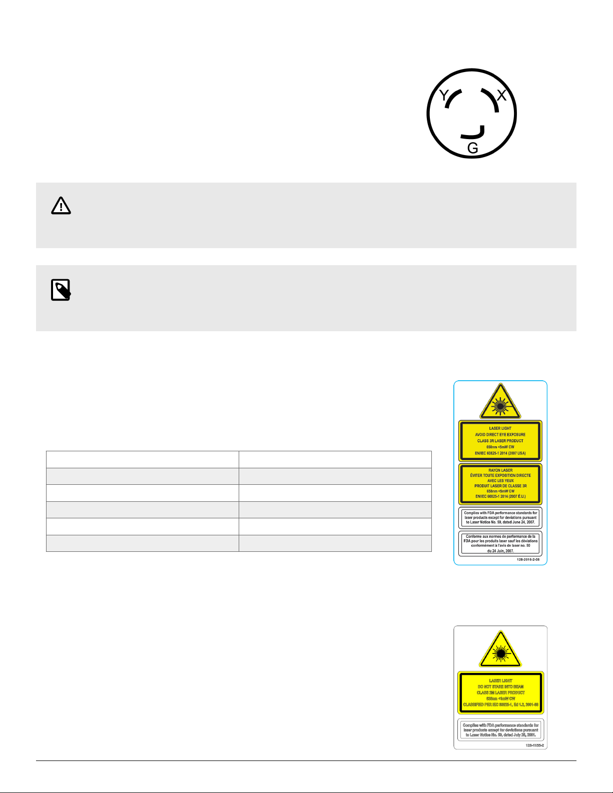
• EN/IEC Class 3R Laser Product Cercaon is shown on Decal 128-2016-2-08. This label shows the EN/IEC standards
for a Class 3R Laser Product.
• An explanaon of FDA compliance standards is shown on Decal 128-2016-2-08. FDA performance standards compli-
ance is shown on the decal.
• For units with TDC Laser, FDA standards for Class 2M laser compliance are shown on Decal 128-1155-2.
• Decal 128-381-2 warns the operator not to remove the covered of the SW Pro because of the risk of the electrical shock
and not to use below garage oor level.
• ETL cercaon standards are outlined on Decal 128-1120-2. Users are cauoned not to use the balancer below garage
level.
• A manufacturer's idencaon is also on the rear of the balancer.
SmartWeight® Pro Operations Manual
Page 5 of 11

2.2.6. Balancer Power Source Precaution
The is intended to operate from a power source that will apply 230VAC +10% /
-15%, 1 phase, 10 amp 50/60 Hz power.
The power cable includes NEMA 20 amp plug, L6-20P, between the supply con-
ductors of the power cord.
The power cord supplied ulizes a twist lock connector.
CAUTION
A protecve ground connecon, through the grounding conductor is the power cord, is essenal for safe
operaon. Use only a power cord that is in good condion.
NOTE
For informaon on converng from single phase NEMA L6-20P plug to a three phase NEMA L15-20P plug
refer to Form 5350-T
2.2.7. Optical Scan Laser Precaution
The Opcal Scan Laser is a Class 3R laser designed to measure the prole of wheel
assemblies.
The laser is not a eld serviceable part.
No maintenance is to be performed on the laser.
Wavelength: 658nm
Laser Power for Classicaon: <5mW
Emission Type: CW
Divergence: 3.0 mRad
Beam Diameter: 8.5 mm at aperture
Fan Angle: 57°
2.2.8. HammerHead TDC Laser Precaution (optional equipment)
The TDC (Top Dead Center) Laser Indicator is a class 2M laser designed to aid in
applying clip-on weights. The laser is not a eld serviceable or adjustable part. Use
cauon in regard to reecve materials around the laser and never look into the laser
beam.
LASER RADIATION - DO NOT STARE INTO THE BEAM OR VIEW DIRECTLY WITH
OPTICAL INSTRUMENTS.
Viewing the laser output with magniers or related opcal instruments within a dis-
tance of 100mm from the laser aperture may pose an eye hazard.
SmartWeight® Pro Operations Manual
Page 6 of 11

2.2.9. Turning Power ON / OFF
PUSH BUTTON SWITCH
The balancer is equipped with a push buon power switch located on the le
side of the LCD support. Use this switch for normal shut down and restarng
procedures.
CAUTION
Always use the power buon on the LCD support turn on/o in
order to prevent data loss.
MAIN POWER SWITCH
The main power ON/OFF switch is located on the back of the balancer cabinet.
To power the balancer “ON,” press the “I” side of the ON/OFF switch. To turn all
power the balancer “OFF,” press the “O” side of the ON/OFF switch.
2.2.10. Equipment Specifications
Only a Hunter Factory-Authorized Representave should perform installaon. This equipment contains no operator serv-
iceable parts. All maintenance and repairs must be referred to a qualied Hunter Service Representave.
Table 1. Equipment Specicaons
Electrical
Voltage: 230VAC +10% / -15%, 1phase, 50/60 Hz, power cable includes NEMA 20
amp plug, L6-20P
Amperage: 10 amperes
Waage: 3450 was (peak)
Air
Air Pressure Requirements: 100-175 PSI (6.9-12 bar)
Approximate Air Consumpon: 4 CFM (110 Liters/Minute)
Atmospherics
Temperature: +32°F to +122°F (0°C to +50°C)
Relave Humidity: Up to 95% Non-condensing
Altude: Up to 10,000 . (3048 m)
SmartWeight® Pro Operations Manual
Page 7 of 11

3. SmartWeight® Pro Main Screen
1. Clip Weight Plane 6. SmartWeight® Menu Buon
2. Tape Weight Plane 7. Imbalance & Couple Force Display
3. Context Sensive Menu 8. SmartWeight Savings Total
4. Wheel Assembly Display 9. Animated Instrucon Display
5. Start / Stop Buon
SmartWeight® Pro Operations Manual
Page 8 of 11

4. Operation
4.1. Getting Wheel On Balancer
CAUTION
Use two hands to maintain control of the wheel
Slide proper collet onto spindle sha. Posion wheel li carriage (“li”) at the end of the li rail. Press the foot pedal down
to lower li. Roll wheel onto the li. Raise foot pedal to raise wheel into posion to slide it on spindle. Center wheel on
collet and clamp. Keep li under wheel and close hood. Li will automacally lower.
TIP
Allowing the balancer to lower li will speed up removal.
4.2. Remove Wheel From Balancer
Place li under wheel and raise it to wheel. Remove wheel clamp. Slide li with wheel on it to end of li rail. Use pedal to
lower li.
4.3. Centering Check
CenteringCheck® is an inspecon or vericaon of the wheel’s mount to balance to idenfy possible centering errors, thus
recognizing improper measurements. From the main balance screen, touch the “CenteringCheck” buon.
4.4. Print Summary
From the main balance screen, select “Print” → “Vehicle Summary”. The Vehicle Summary screen will be displayed.
4.5. Hunter Help Video Player
On main balancer screen, touch Help → Launch Video Player buon.
Select balancer topic from video menu.
SmartWeight® Pro Operations Manual
Page 9 of 11

5. Maintenance and Calibration
5.1. Auto Calibration
The balancer ulizes automac calibraon procedure. Once the balancer is calibrated at installaon me, no further
operator input is required.
5.2. Cleaning the Console
To maintain a brand new appearance of the display, clean with so cloth regularly.
Please remove stubborn stains with so cleaner rather than strong cleaners such as dilung agent, benzene or corrosive
cleaner as they may damage the display. ArmorAll wipes are a suitable cleaning product for the touch screen.
CAUTION
Do not touch the screen with chemicals or solvents on ngers, i.e. brake cleaner. Doing so will damage the
an-glare protector on the screen.
5.3. Maintenance Schedule
5.4. End User License Agreement
Use of equipment and it’s operang soware is acknowledgment of agreement to the terms
of the End User Licensing Agreement (“EULA”). The enre EULA can be found by scanning the
QR Code.
SmartWeight® Pro Operations Manual
Page 10 of 11

6. Warranty Information
Hunter Engineering Company warrants new equipment to be free from defects in material and workmanship under normal
condions of use for a period of three (3) years from the date of installaon. Excepons to this warranty are listed below:
• Field labor is covered under this warranty for a period of six (6) months.
• ADASLinkTM units carry a one (1) year warranty and remain under warranty as long as a subscripon is maintained there
aer.
• DAS 3000 units, including electronic circuit boards, carry a one (1) year warranty.
• Printers carry a one (1) year warranty.
• Normal consumables and wear items are not covered. Excepon is baeries, which are warranted for a period of six (6)
months.
• Product that has been subject to abuse, misuse, alteraons, accident, exposure to the elements,tampering, unreasonable
use, or not maintained in a reasonable or necessary manner.
• Replacement parts purchased through the Hunter Service Center and no longer covered by machine warranty are
warranted for a period of six (6) months.
In case of any warranty claim, it will be necessary to contact your local authorized Hunter Service Representave. To have
an item considered for warranty, it must be returned to Hunter Engineering Company for inspecon and evaluaon. This
must be done on a freight prepaid basis. If aer our inspecon the product proves to be defecve, and is within the me
frame specied, we will repair or replace the item at no addional cost.
This is Hunter Engineering Company’s only warranty with respect to new equipment. Hunter Engineering Company
disclaims all other warranes to the extent permied by law. This express warranty and any implied warranes of
merchantability and tness for a parcular purpose shall not extend beyond the warranty period. Hunter Engineering
Company is not responsible for any incidental or consequenal damages, including, but not limited to, loss of business.
We do not authorize any person to assume for us any other liabilies with our products. Any remaining warranty may be
transferred to subsequent purchasers by forwarding the purchaser’s name, address,phone number and equipment serial
number to:
See our document library at www.Hunter.com for addional details.
Hunter Engineering Company | Customer Service Department
11250 Hunter Drive, Bridgeton, MO 63044
(800) 448-6848
Form 3221-T, Updated: 06-2021, Supersedes 12-17a
SmartWeight® Pro Operations Manual
Page 11 of 11

Visit hunter.com/training for more information
Hunter Training
Develop the skills and Knowledge to excel
hunter.com/training
Hunter Engineering Company leads
the under-vehicle service equipment
industry & accepts the responsibility
to train tomorrow’s technicians.
Based on Hunter’s know-how and
industry-leading technology, Hunter
Training begins with concept theory
and discussion (40%) and nishes
with hands-on training (60%).
All Hunter Training classes are led
by ASE-certied instructors and all
training material is kept up-to-date
through a rigorous curriculum review
process.
Other manuals for SmartWeight Pro
1
Table of contents
Other Hunter Wheel Balancer manuals

Hunter
Hunter DSP9600 User manual

Hunter
Hunter Road Force Touch GSP9700 Series User manual

Hunter
Hunter SmartWeight Touch User manual

Hunter
Hunter SmartWeight Pro Series User manual

Hunter
Hunter GSP9200 Series User manual

Hunter
Hunter Road Force Elite GSP9700 Series User manual

Hunter
Hunter GSP9712 User manual

Hunter
Hunter Road Force Elite GSP9700 Series User manual

Hunter
Hunter GSP9720JLR User manual

Hunter
Hunter SmartWeight Elite User manual