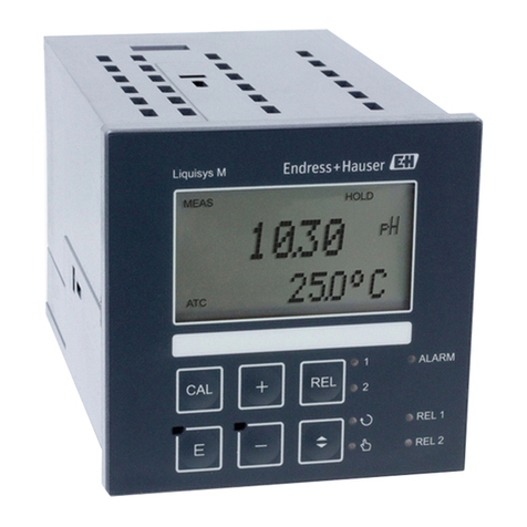
Liquisys M CPM223/253
Endress+Hauser 3
Table of contents
1 Safety instructions . . . . . . . . . . . . . . . . 5
1.1 Designated use . . . . . . . . . . . . . . . . . . . . . . . . . . . . 5
1.2 Installation, commissioning and operation . . . . . . . . 5
1.3 Operational safety . . . . . . . . . . . . . . . . . . . . . . . . . . 5
1.4 Return . . . . . . . . . . . . . . . . . . . . . . . . . . . . . . . . . . . 6
1.5 Notes on safety icons and symbols . . . . . . . . . . . . . . 6
2 Identification . . . . . . . . . . . . . . . . . . . . 7
2.1 Device designation . . . . . . . . . . . . . . . . . . . . . . . . . 7
2.1.1 Nameplate . . . . . . . . . . . . . . . . . . . . . . . . . 7
2.1.2 Product structure . . . . . . . . . . . . . . . . . . . . 7
2.1.3 Additional functions of the Plus Package . . . 8
2.2 Scope of delivery . . . . . . . . . . . . . . . . . . . . . . . . . . . 8
2.3 Certificates and approvals . . . . . . . . . . . . . . . . . . . . 8
3 Installation . . . . . . . . . . . . . . . . . . . . . . 9
3.1 Quick installation guide . . . . . . . . . . . . . . . . . . . . . . 9
3.1.1 Measuring system . . . . . . . . . . . . . . . . . . . . 9
3.2 Incoming acceptance, transport, storage . . . . . . . . . 10
3.3 Installation conditions . . . . . . . . . . . . . . . . . . . . . . 10
3.3.1 Field instrument . . . . . . . . . . . . . . . . . . . . 10
3.3.2 Panel-mounted instrument . . . . . . . . . . . . 11
3.4 Installation instructions . . . . . . . . . . . . . . . . . . . . . 12
3.4.1 Field instrument . . . . . . . . . . . . . . . . . . . . 12
3.4.2 Panel-mounted instrument . . . . . . . . . . . . 15
3.5 Post-installation check . . . . . . . . . . . . . . . . . . . . . . 15
4 Wiring . . . . . . . . . . . . . . . . . . . . . . . . 16
4.1 Electrical connection without Memosens
functionality . . . . . . . . . . . . . . . . . . . . . . . . . . . . . 17
4.1.1 Connection diagram . . . . . . . . . . . . . . . . . 17
4.1.2 Measuring cable and sensor connection . . . 19
4.2 Electrical connection with Memosens
functionality . . . . . . . . . . . . . . . . . . . . . . . . . . . . . 23
4.2.1 Connection diagram . . . . . . . . . . . . . . . . . 23
4.2.2 Measuring cable and sensor connection . . . 25
4.3 Alarm contact . . . . . . . . . . . . . . . . . . . . . . . . . . . . 27
4.4 Post-connection check . . . . . . . . . . . . . . . . . . . . . . 27
5 Operation . . . . . . . . . . . . . . . . . . . . . . 28
5.1 Quick operation guide . . . . . . . . . . . . . . . . . . . . . . 28
5.2 Display and operating elements . . . . . . . . . . . . . . . 28
5.2.1 Display . . . . . . . . . . . . . . . . . . . . . . . . . . . 28
5.2.2 Operating elements . . . . . . . . . . . . . . . . . . 29
5.2.3 Key assignment . . . . . . . . . . . . . . . . . . . . . 30
5.3 Local Operation . . . . . . . . . . . . . . . . . . . . . . . . . . . 32
5.3.1 Automatic/manual mode . . . . . . . . . . . . . . 32
5.3.2 Operating concept . . . . . . . . . . . . . . . . . . . 33
5.4 System configuration . . . . . . . . . . . . . . . . . . . . . . . 35
5.4.1 Setup 1 (pH / Redox) . . . . . . . . . . . . . . . . 35
5.4.2 Setup 2 (temperature) . . . . . . . . . . . . . . . . 37
5.4.3 Current input . . . . . . . . . . . . . . . . . . . . . . 38
5.4.4 Current outputs . . . . . . . . . . . . . . . . . . . . . 41
5.4.5 Monitoring functions . . . . . . . . . . . . . . . . . 45
5.4.6 Relay contact configuration . . . . . . . . . . . . 50
5.4.7 Service . . . . . . . . . . . . . . . . . . . . . . . . . . . 62
5.4.8 E+H Service . . . . . . . . . . . . . . . . . . . . . . . 63
5.4.9 Interfaces . . . . . . . . . . . . . . . . . . . . . . . . . . 64
5.5 Communication . . . . . . . . . . . . . . . . . . . . . . . . . . . 64
5.6 Calibration . . . . . . . . . . . . . . . . . . . . . . . . . . . . . . 65
6 Commissioning . . . . . . . . . . . . . . . . . . 71
6.1 Things to note when commissioning
digital sensors . . . . . . . . . . . . . . . . . . . . . . . . . . . . 71
6.2 Things to note when commissioning I
SFET sensors . . . . . . . . . . . . . . . . . . . . . . . . . . . . . 71
6.3 Function check . . . . . . . . . . . . . . . . . . . . . . . . . . . 71
6.4 Switching on . . . . . . . . . . . . . . . . . . . . . . . . . . . . . 72
6.5 Quick start-up . . . . . . . . . . . . . . . . . . . . . . . . . . . . 74
7 Maintenance . . . . . . . . . . . . . . . . . . . . 76
7.1 Maintenance transmitter . . . . . . . . . . . . . . . . . . . . 76
7.1.1 Dismantling of panel mounted instrument . 76
7.1.2 Dismantling of field instrument . . . . . . . . . 77
7.1.3 Replacing the controller . . . . . . . . . . . . . . . 77
7.2 Maintenance of the entire measuring point . . . . . . . 78
7.2.1 Cleaning the transmitter . . . . . . . . . . . . . . 78
7.2.2 Cleaning the pH/Redox sensors . . . . . . . . . 79
7.2.3 Maintaining digital sensors . . . . . . . . . . . . . 79
7.2.4 Liquid KCl supply . . . . . . . . . . . . . . . . . . . 80
7.2.5 Assembly . . . . . . . . . . . . . . . . . . . . . . . . . . 80
7.2.6 Connecting lines and junction boxes . . . . . 80
7.3 "Optoscope" service tool . . . . . . . . . . . . . . . . . . . . 80
8 Accessories . . . . . . . . . . . . . . . . . . . . . 81
8.1 Sensors . . . . . . . . . . . . . . . . . . . . . . . . . . . . . . . . . 81
8.2 Connection accessories . . . . . . . . . . . . . . . . . . . . . 81
8.3 Mounting accessories . . . . . . . . . . . . . . . . . . . . . . . 82
8.4 Assemblies . . . . . . . . . . . . . . . . . . . . . . . . . . . . . . . 84
8.5 Software and hardware add-ons . . . . . . . . . . . . . . . 84
8.6 Calibration solutions . . . . . . . . . . . . . . . . . . . . . . . 85
8.7 Optoscope . . . . . . . . . . . . . . . . . . . . . . . . . . . . . . . 85
