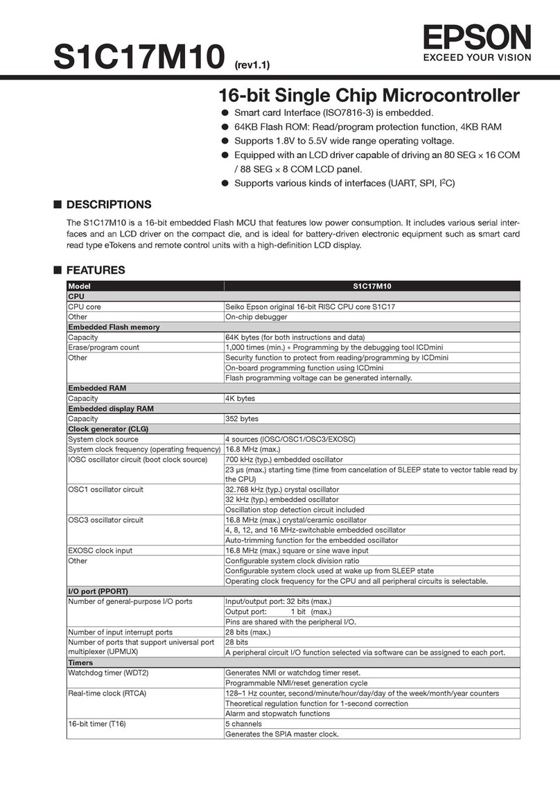
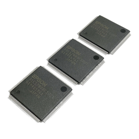
Epson S1C17001 User manual

Technical Manual
S1C17001
CMOS 16-BIT SINGLE CHIP MICROCONTROLLER

NOTICE
No part of this material may be reproduced or duplicated in any form or by any means without the written permission
of Seiko Epson. Seiko Epson reserves the right to make changes to this material without notice. Seiko Epson does not
assume any liability of any kind arising out of any inaccuracies contained in this material or due to its application or
use in any product or circuit and, further, there is no representation that this material is applicable to products requir-
ing high level reliability, such as medical products. Moreover, no license to any intellectual property rights is granted by
implication or otherwise, and there is no representation or warranty that anything made in accordance with this mate-
rial will be free from any patent or copyright infringement of a third party. This material or portions thereof may contain
technology or the subject relating to strategic products under the control of the Foreign Exchange and Foreign Trade
Law of Japan and may require an export license from the Ministry of Economy, Trade and Industry or other approval
from another government agency.
© SEIKO EPSON CORPORATION 2010, All rights reserved.
All brands or product names mentioned herein are trademarks and/or registered trademarks of their respective compa-
nies.

S1C17001 TECHNICAL MANUAL EPSON i
- Contents -
1 Overview ........................................................................................................................1-1
1.1 Features .......................................................................................................................... 1-1
1-2 Block Diagram ................................................................................................................ 1-2
1.3 Pins ................................................................................................................................. 1-3
1.3.1 Pinout Diagram ................................................................................................. 1-3
1.3.2 Pin Descriptions................................................................................................ 1-4
2 CPU................................................................................................................................2-1
2.1 S1C17 Core Features...................................................................................................... 2-1
2.2 CPU Registers................................................................................................................. 2-2
2.3 Command Set................................................................................................................. 2-3
2.4 Vector Table .................................................................................................................... 2-7
2.5 Processor Information..................................................................................................... 2-8
3 Memory Map and Bus Control......................................................................................3-1
3.1 Bus Cycle........................................................................................................................ 3-2
3.1.1 Access Size Restrictions .................................................................................. 3-2
3.1.2 Command Execution Cycle Restrictions .......................................................... 3-2
3.2 Internal ROM Area........................................................................................................... 3-3
3.2.1 Internal ROM..................................................................................................... 3-3
3.2.2 ROM Read Access Cycle Settings ................................................................... 3-3
0x5320: ROM Control Register (MISC_FL) ............................................................................... 3-3
3.3 Internal RAM Area........................................................................................................... 3-4
3.3.1 Internal RAM ..................................................................................................... 3-4
3.4 Internal Peripheral Circuit Area ....................................................................................... 3-5
3.4.1 Internal Peripheral Circuit Area 1 (0x4000 onward) .......................................... 3-5
3.4.2 Internal Peripheral Circuit Area 2 (0x5000 onward) .......................................... 3-5
3.4.3 I/O Map............................................................................................................. 3-6
3.5 Core I/O Reserved Area .................................................................................................. 3-9
4 Power Supply Voltage ...................................................................................................4-1
5 Initial Reset ....................................................................................................................5-1
5.1 Initial Reset Factors ........................................................................................................ 5-1
5.1.1 #RESET pin....................................................................................................... 5-1
5.1.2 P0 Port Key-Entry Reset................................................................................... 5-2
5.1.3 Reset by Watchdog Timer ................................................................................ 5-2
5.2 Initial Reset Sequence .................................................................................................... 5-3
5.3 Initial Settings at Initial Resetting.................................................................................... 5-4
6 Interrupt Controller (ITC) ...............................................................................................6-1
6.1 ITC Configuration............................................................................................................ 6-1
6.2 Vector Table .................................................................................................................... 6-2
6.3 Maskable Interrupt Control ............................................................................................. 6-3
6.3.1 ITC Enable ........................................................................................................ 6-3
6.3.2 Interrupt Request from Peripheral Module and Interrupt Flag.......................... 6-3
6.3.3 Interrupt Permission/Prohibition....................................................................... 6-4
6.3.4 Processing for Multiple Interrupts .................................................................... 6-5
6.3.5 Interrupt Trigger Modes .................................................................................... 6-6
6.3.6 S1C17 Core Interrupt Processing..................................................................... 6-8
6.4 NMI.................................................................................................................................. 6-9
6.5 Software Interrupts ........................................................................................................ 6-10

ii EPSON S1C17001 TECHNICAL MANUAL
6.6 HALT and SLEEP Mode Cancellation by Interrupt Factors ........................................... 6-11
6.7 Control Register Details ................................................................................................. 6-12
0x4300: Interrupt Flag Register (ITC_IFLG).............................................................................. 6-13
0x4302: Interrupt Enable Register (ITC_EN)............................................................................. 6-15
0x4304: ITC Control Register (ITC_CTL).................................................................................. 6-16
0x4306: External Interrupt Level Setup Register 0 (ITC_ELV0) ................................................ 6-17
0x4308: External Interrupt Level Setup Register 1 (ITC_ELV1) ................................................ 6-18
0x430a: External Interrupt Level Setup Register 2 (ITC_ELV2) ................................................ 6-19
0x430c: External Interrupt Level Setup Register 3 (ITC_ELV3) ................................................ 6-20
0x430e: Internal Interrupt Level Setup Register 0 (ITC_ILV0)................................................... 6-21
0x4310: Internal Interrupt Level Setup Register 1 (ITC_ILV1)................................................... 6-22
0x4312: Internal Interrupt Level Setup Register 2 (ITC_ILV2)................................................... 6-23
0x4314: Internal Interrupt Level Setup Register 3 (ITC_ILV3)................................................... 6-24
6.8 Precautions .................................................................................................................... 6-25
7 Oscillator Circuit (OSC) .................................................................................................7-1
7.1 OSC Module Configuration............................................................................................. 7-1
7.2 OSC3 Oscillator Circuit................................................................................................... 7-2
7.3 OSC1 Oscillator Circuit................................................................................................... 7-4
7.4 System Clock Switching ................................................................................................. 7-5
7.5 8-bit OSC1 Timer Clock Control..................................................................................... 7-6
7.6 Clock External Output (FOUT3, FOUT1)......................................................................... 7-7
7.7 RESET and NMI Input Noise Filters ................................................................................ 7-9
7.8 Control Register Details ................................................................................................. 7-10
0x5060: Clock Source Select Register (OSC_SRC)................................................................. 7-11
0x5061: Oscillation Control Register (OSC_CTL)..................................................................... 7-12
0x5062: Noise Filter Enable Register (OSC_NFEN) ................................................................. 7-13
0x5064: FOUT Control Register (OSC_FOUT) ......................................................................... 7-14
0x5065: T8OSC1 Clock Control Register (OSC_T8OSC1) ...................................................... 7-15
7.9 Precautions .................................................................................................................... 7-16
8 Clock Generator (CLG)..................................................................................................8-1
8.1 Clock Generator Configuration ....................................................................................... 8-1
8.2 CPU Core Clock (CCLK) Control .................................................................................... 8-2
8.3 Peripheral Module Clock (PCLK) Control........................................................................ 8-3
8.4 Control Register Details .................................................................................................. 8-4
0x5080: PCLK Control Register (CLG_PCLK)........................................................................... 8-5
0x5081: CCLK Control Register (CLG_CCLK) .......................................................................... 8-6
8.5 Precautions ..................................................................................................................... 8-7
9 Prescaler (PSC)..............................................................................................................9-1
9.1 Prescaler Configuration .................................................................................................. 9-1
9.2 Control Register Details .................................................................................................. 9-2
0x4020: Prescaler Control Register (PSC_CTL)........................................................................ 9-2
9.3 Precautions ..................................................................................................................... 9-3
10 Input/Output Port (P)..................................................................................................10-1
10.1 Input/Output Port Configuration .................................................................................. 10-1
10.2 Input/Output Port Pin Function Selection (Port MUX) ................................................. 10-2
10.3 Data Input/Output ........................................................................................................ 10-3
10.4 Pull-up Control............................................................................................................. 10-4
10.5 Input Interface Level .................................................................................................... 10-5
10.6
P0 Port Chattering Filter Function................................................................................ 10-6
10.7 Port Input Interrupt....................................................................................................... 10-7

S1C17001 TECHNICAL MANUAL EPSON iii
10.8 Control Register Details .............................................................................................. 10-10
0x5200/0x5210/0x5220/0x5230: PxPort Input Data Registers (Px_IN).................................. 10-11
0x5201/0x5211/0x5221/0x5231: PxPort Output Data Registers (Px_OUT)........................... 10-12
0x5202/0x5212/0x5222/0x5232: PxPort I/O Direction Control Registers (Px_IO) ................. 10-13
0x5203/0x5213/0x5223/0x5233: PxPort Pull-up Control Registers (Px_PU)......................... 10-14
0x5205/5215: PxPort Interrupt Mask Registers (Px_IMSK).................................................... 10-15
0x5206/5216: PxPort Interrupt Edge Select Registers (Px_EDGE) ........................................ 10-16
0x5207/5217: PxPort Interrupt Flag Registers (Px_IFLG)....................................................... 10-17
0x5208: P0 Port Chattering Filter Control Register (P0_CHAT) .............................................. 10-18
0x5209: P0 Port Key-Entry Reset Configuration Register (P0_KRST) .................................... 10-19
0x52a0: P0 Port Function Select Register (P0_PMUX) ........................................................... 10-20
0x52a1: P1 Port Function Select Register (P1_PMUX) ........................................................... 10-21
0x52a2: P2 Port Function Select Register (P2_PMUX) ........................................................... 10-22
0x52a3: P3 Port Function Select Register (P3_PMUX) ........................................................... 10-23
10.9 Precautions ................................................................................................................. 10-24
11 16-bit Timer (T16) .......................................................................................................11-1
11.1 16-bit Timer Overview.................................................................................................. 11-1
11.2 16-bit Timer Operating Modes..................................................................................... 11-2
11.2.1 Internal Clock Mode ...................................................................................... 11-2
11.2.2 External Clock Mode ..................................................................................... 11-3
11.2.3 Pulse Width Measurement Mode .................................................................. 11-4
11.3 Count Mode ................................................................................................................. 11-5
11.4 16-bit Timer Reload Register and Underflow Cycle .................................................... 11-6
11.5 16-bit Timer Reset ....................................................................................................... 11-7
11.6 16-bit Timer RUN/STOP Control.................................................................................. 11-8
11.7 16-bit Timer Output Signal........................................................................................... 11-9
11.8 16-bit Timer Interrupts ................................................................................................ 11-10
11.9 Control Register Details .............................................................................................. 11-11
0x4220/0x4240/0x4260: 16-bit Timer Ch.xInput Clock Select Registers (T16_CLKx)........... 11-12
0x4222/0x4242/0x4262: 16-bit Timer Ch.xReload Data Registers (T16_TRx)....................... 11-13
0x4224/0x4244/0x4264: 16-bit Timer Ch.xCounter Data Registers (T16_TCx)..................... 11-14
0x4226/0x4246/0x4266: 16-bit Timer Ch.xControl Registers (T16_CTLx)............................. 11-15
11.10 Precautions ............................................................................................................... 11-17
12 8-bit Timer (T8F) .........................................................................................................12-1
12.1 8-bit Timer Overview.................................................................................................... 12-1
12.2 8-bit Timer Count Mode............................................................................................... 12-2
12.3 Count Clock ................................................................................................................. 12-3
12.4 8-bit Timer Reload Register and Underflow Cycle ...................................................... 12-4
12.5 8-bit Timer Reset ......................................................................................................... 12-5
12.6 8-bit Timer RUN/STOP Control.................................................................................... 12-6
12.7 8-bit Timer Output Signal............................................................................................. 12-7
12.8 Fine Mode .................................................................................................................... 12-8
12.9 8-bit Timer Interrupts ................................................................................................... 12-9
12.10 Control Register Details ............................................................................................ 12-10
0x4200: 8-bit Timer Input Clock Select Register (T8F_CLK) .................................................. 12-11
0x4202: 8-bit Timer Reload Data Register (T8F_TR)............................................................... 12-12
0x4204: 8-bit Timer Counter Data Register (T8F_TC)............................................................. 12-13
0x4206: 8-bit Timer Control Register (T8F_CTL)..................................................................... 12-14
12.11 Precautions ............................................................................................................... 12-16

iv EPSON S1C17001 TECHNICAL MANUAL
13 PWM & Capture Timer (T16E) ....................................................................................13-1
13.1 PWM & Capture Timer Overview ................................................................................. 13-1
13.2 PWM & Capture Timer Operating Modes .................................................................... 13-2
13.3 Setting and Resetting Counter Value........................................................................... 13-3
13.4 Compare Data Settings................................................................................................ 13-4
13.5 PWM & Capture Timer RUN/STOP Control ................................................................. 13-5
13.6 Clock Output Control ................................................................................................... 13-6
13.7 PWM & Capture Timer Interrupts................................................................................. 13-9
13.8 Control Register Details .............................................................................................. 13-11
0x5300: PWM Timer Compare Data A Register (T16E_CA).................................................... 13-12
0x5302: PWM Timer Compare Data B Register (T16E_CB).................................................... 13-13
0x5304: PWM Timer Counter Data Register (T16E_TC) ......................................................... 13-14
0x5306: PWM Timer Control Register (T16E_CTL) ................................................................. 13-15
0x5308: PWM Timer Input Clock Select Register (T16E_CLK) ............................................... 13-17
0x530a: PWM Timer Interrupt Mask Register (T16E_IMSK) ................................................... 13-18
0x530c: PWM Timer Interrupt Flag Register (T16E_IFLG) ...................................................... 13-19
13.9 Precautions ................................................................................................................. 13-20
14 8-bit OSC1 Timer (T8OSC1) .......................................................................................14-1
14.1 8-bit OSC1 Timer Overview ......................................................................................... 14-1
14.2 8-bit OSC1 Timer Count Mode .................................................................................... 14-2
14.3 Count Clock ................................................................................................................. 14-3
14.4 Resetting 8-bit OSC1 Timer......................................................................................... 14-4
14.5 Compare Data Settings................................................................................................ 14-5
14.6 8-bit OSC1 Timer RUN/STOP Control......................................................................... 14-6
14.7 8-bit OSC1 Timer Interrupts......................................................................................... 14-7
14.8 Control Register Details ............................................................................................... 14-9
0x50c0: 8-bit OSC1 Timer Control Register (T8OSC1_CTL) .................................................. 14-10
0x50c1: 8-bit OSC1 Timer Counter Data Register (T8OSC1_CNT) ........................................ 14-11
0x50c2: 8-bit OSC1 Timer Compare Data Register (T8OSC1_CMP) ..................................... 14-12
0x50c3: 8-bit OSC1 Timer Interrupt Mask Register (T8OSC1_IMSK)..................................... 14-13
0x50c4: 8-bit OSC1 Timer Interrupt Flag Register (T8OSC1_IFLG)........................................ 14-14
14.9 Precautions ................................................................................................................. 14-15
15 Clock Timer (CT).........................................................................................................15-1
15.1 Clock Timer Overview .................................................................................................. 15-1
15.2 Operation Clock ........................................................................................................... 15-2
15.3 Clock Timer Resetting.................................................................................................. 15-3
15.4 Clock Timer RUN/STOP Control.................................................................................. 15-4
15.5 Clock Timer Interrupts ................................................................................................. 15-5
15.6 Control Register Details ............................................................................................... 15-7
0x5000: Clock Timer Control Register (CT_CTL) ..................................................................... 15-8
0x5001: Clock Timer Counter Register (CT_CNT) ................................................................... 15-9
0x5002: Clock Timer Interrupt Mask Register (CT_IMSK) ...................................................... 15-10
0x5003: Clock Timer Interrupt Flag Register (CT_IFLG) ......................................................... 15-11
15.7 Precautions ................................................................................................................. 15-12
16 Stopwatch Timer (SWT) .............................................................................................16-1
16.1 Stopwatch Timer Overview.......................................................................................... 16-1
16.2 BCD Counters.............................................................................................................. 16-2
16.3 Operation Clock ........................................................................................................... 16-3
16.4 Stopwatch Timer Resetting ......................................................................................... 16-4
16.5 Stopwatch Timer RUN/STOP Control.......................................................................... 16-5

S1C17001 TECHNICAL MANUAL EPSON v
16.6 Stopwatch Timer Interrupts ......................................................................................... 16-6
16.7 Control Register Details ............................................................................................... 16-8
0x5020: Stopwatch Timer Control Register (SWT_CTL).......................................................... 16-9
0x5021: Stopwatch Timer BCD Counter Register (SWT_BCNT) ............................................ 16-10
0x5022: Stopwatch Timer Interrupt Mask Register (SWT_IMSK) ........................................... 16-11
0x5023: Stopwatch Timer Interrupt Flag Register (SWT_IFLG) .............................................. 16-12
16.8 Precautions ................................................................................................................. 16-13
17 Watchdog Timer (WDT) ..............................................................................................17-1
17.1 Watchdog Timer Overview........................................................................................... 17-1
17.2 Operation Clock ........................................................................................................... 17-2
17.3 Watchdog Timer Control.............................................................................................. 17-3
17.3.1 NMI/Reset Mode Selection............................................................................ 17-3
17.3.2 Watchdog Timer Run/Stop Control ............................................................... 17-3
17.3.3 Watchdog Timer Resetting ............................................................................ 17-3
17.3.4 Operation in Standby Mode .......................................................................... 17-3
17.4 Control Register Details ............................................................................................... 17-4
0x5040: Watchdog Timer Control Register (WDT_CTL)........................................................... 17-5
0x5041: Watchdog Timer Status Register (WDT_ST) .............................................................. 17-6
17.5 Precautions .................................................................................................................. 17-7
18 UART...........................................................................................................................18-1
18.1 UART Configuration ..................................................................................................... 18-1
18.2 UART Pin...................................................................................................................... 18-2
18.3 Transfer Clock .............................................................................................................. 18-3
18.4 Transfer Data Settings.................................................................................................. 18-4
18.5 Data Transfer Control ................................................................................................... 18-5
18.6 Receive Errors.............................................................................................................. 18-8
18.7 UART Interrupts ........................................................................................................... 18-9
18.8 IrDA Interface .............................................................................................................. 18-11
18.9 Control Register Details .............................................................................................. 18-13
0x4100: UART Status Register (UART_ST) ............................................................................. 18-14
0x4101: UART Transmit Data Register (UART_TXD)............................................................... 18-16
0x4102: UART Receive Data Register (UART_RXD) ............................................................... 18-17
0x4103: UART Mode Register (UART_MOD) .......................................................................... 18-18
0x4104: UART Control Register (UART_CTL) ......................................................................... 18-19
0x4105: UART Expansion Register (UART_EXP) .................................................................... 18-20
18.10 Precautions ............................................................................................................... 18-21
19 SPI...............................................................................................................................19-1
19.1 SPI Configuration......................................................................................................... 19-1
19.2 SPI Input/Output Pins .................................................................................................. 19-2
19.3 SPI Clock ..................................................................................................................... 19-3
19.4 Data Transfer Condition Settings ................................................................................. 19-4
19.5 Data Transfer Control ................................................................................................... 19-5
19.6 SPI Interrupts ............................................................................................................... 19-8
19.7 Control Register Details .............................................................................................. 19-10
0x4320: SPI Status Register (SPI_ST)..................................................................................... 19-11
0x4322: SPI Transmit Data Register (SPI_TXD) ...................................................................... 19-12
0x4324: SPI Receive Data Register (SPI_RXD)....................................................................... 19-13
0x4326: SPI Control Register (SPI_CTL)................................................................................. 19-14
19.8 Precautions ................................................................................................................. 19-16

vi EPSON S1C17001 TECHNICAL MANUAL
20 I2C................................................................................................................................20-1
20.1 I2C Configuration.......................................................................................................... 20-1
20.2 I2C Input/Output Pins................................................................................................... 20-2
20.3 I2C Clock ...................................................................................................................... 20-3
20.4 Settings Before Data Transfer ...................................................................................... 20-4
20.5 Data Transfer Control ................................................................................................... 20-5
20.6 I2C Interrupts............................................................................................................... 20-11
20.7 Control Register Details .............................................................................................. 20-13
0x4340: I2C Enable Register (I2C_EN) .................................................................................... 20-14
0x4342: I2C Control Register (I2C_CTL).................................................................................. 20-15
0x4344: I2C Data Register (I2C_DAT) ...................................................................................... 20-17
0x4346: I2C Interrupt Control Register (I2C_ICTL) .................................................................. 20-19
21 Remote Controller (REMC).........................................................................................21-1
21.1 REMC Configuration .................................................................................................... 21-1
21.2 REMC Input/output Pin................................................................................................ 21-2
21.3 Carrier Generation........................................................................................................ 21-3
21.4 Data Length Counter Clock Settings ........................................................................... 21-4
21.5 Data Transfer Control ................................................................................................... 21-5
21.6 REMC Interrupts .......................................................................................................... 21-8
21.7 Control Register Details .............................................................................................. 21-10
0x5340: REMC Configuration Register (REMC_CFG) ............................................................. 21-11
0x5341: REMC Prescaler Clock Select Register (REMC_PSC) .............................................. 21-12
0x5342: REMC H Carrier Length Setup Register (REMC_CARH)........................................... 21-13
0x5343: REMC L Carrier Length Setup Register (REMC_CARL)............................................ 21-14
0x5344: REMC Status Register (REMC_ST) ........................................................................... 21-15
0x5345: REMC Length Counter Register (REMC_LCNT)........................................................ 21-16
0x5346: REMC Interrupt Mask Register (REMC_IMSK).......................................................... 21-17
0x5347: REMC Interrupt Flag Register (REMC_IFLG)............................................................. 21-18
21.8 Precautions ................................................................................................................. 21-19
22 On-chip Debugger (DBG)...........................................................................................22-1
22.1 Resource Requirements and Debugging Tool ............................................................. 22-1
22.2 Debug Break Operation Status.................................................................................... 22-2
22.3 Control Register Details ............................................................................................... 22-3
0x5322: OSC1 Peripheral Control Register (MISC_OSC1) ...................................................... 22-4
0xffff90: Debug RAM Base Register (DBRAM)......................................................................... 22-5
23 Basic External Connection Diagram .........................................................................23-1
24 Electrical Characteristics ...........................................................................................24-1
24.1 Absolute Maximum Ratings ......................................................................................... 24-1
24.2 Recommended Operating Conditions ......................................................................... 24-1
24.3 DC Characteristics....................................................................................................... 24-2
24.4 Consumption Current................................................................................................... 24-3
24.5 AC Characteristics ....................................................................................................... 24-4
24.5.1 SPI AC Characteristics .................................................................................. 24-4
24.5.2 I2C AC Characteristics................................................................................... 24-4
24.5.3 External Clock Input AC Characteristics ....................................................... 24-5
24.5.4 System AC Characteristics............................................................................ 24-5
24.6 Oscillation Characteristics ........................................................................................... 24-6
25 Package ......................................................................................................................25-1

S1C17001 TECHNICAL MANUAL EPSON vii
Appendix A I/O Register List ......................................................................................... AP-1
0x4020 Prescaler.................................................................................. AP-4
0x4100–0x4105 UART (with IrDA)...................................................................... AP-5
0x4200–0x4206 8-bit Timer (with Fine Mode).................................................... AP-6
0x4220–0x4266 16-bit Timer ............................................................................. AP-7
0x4300–0x4314 Interrupt Controller .................................................................. AP-9
0x4320–0x4326 SPI .......................................................................................... AP-11
0x4340–0x4346 I2C........................................................................................... AP-12
0x5000–0x5003 Clock Timer ............................................................................ AP-13
0x5020–0x5023 Stopwatch Timer .................................................................... AP-14
0x5040–0x5041 Watchdog Timer ..................................................................... AP-15
0x5060–0x5065 Oscillator................................................................................. AP-16
0x5080–0x5081 Clock Generator ..................................................................... AP-17
0x50c0–0x50c4 8-bit OSC1 Timer.................................................................... AP-18
0x5200–0x52a3 P Port & Port MUX.................................................................. AP-19
0x5300–0x530c PWM & Capture Timer............................................................ AP-21
0x5320–0x5322 MISC Registers....................................................................... AP-22
0x5340–0x5347 Remote Controller .................................................................. AP-23
0xffff80–0xffff90 S1C17 Core I/O ...................................................................... AP-24
Appendix B Power Saving ............................................................................................ AP-25
B.1 Clock Control Power Saving ........................................................................................ AP-25
Appendix C Mounting Precautions............................................................................... AP-28
Appendix D Initialization Routine ................................................................................. AP-31
Appendix E S1C17001 Mask ROM Code Development .............................................. AP-33
Appendix F Revision History......................................................................................... AP-34

1 OVERVIEW
S1C17001 TECHNICAL MANUAL EPSON 1
1 Overview
The S1C7001 is a 16-bit MCU featuring high-speed low-power operations, compact dimensions, wide address
space, and on-chip ICE. In addition to the S1C17 CPU core, it incorporates 32 Kbytes of ROM, 2 Kbytes of RAM,
a serial interface supporting various sensors such as UART, SPI, and I2C high-bit-rate and IrDA1.0 compatibility,
8-bit timer, 16-bit timer, PWM & capture timer, clock timer, stopwatch timer, watchdog timer, and 28 general pur-
pose input/output ports.
It allows 8.2 MHz high-speed operation at an operating voltage of just 1.8 V, and executes single commands using
a single clock with 16-bit RISC processing.
1.1 Features
The main features of the S1C17001 are listed below.
●71C1SerocUPCCSIRtib-61lanigironospE•UPC
●Main (OSC3) oscillator circuit • Crystal oscillator circuit, ceramic oscillator circuit, or external
clock input 8.2 MHz (max)
●Sub (OSC1) oscillator circuit • Crystal oscillator circuit or external clock input 32.768 kHz (typ)
●setybK23•MORlanretnI
●setybK2•MARlanretnI
●larenegtib-82.xaM•troptuptuo/tupnI purpose input/output (shared with periph-
eral circuit input/output pins)
●.hc1)evals/retsam(IPS•ecafretnilaireS
.hc1)elbitapmoc0.1ADrI(TRAU•
I• 2C (master) 1ch.
.hc1)CMER(rellortnocetomeR•
●.hc1)F8T(remittib-8•remiT
.hc3)61T(remittib-61•
.hc1)E61T(remiterutpac&MWP•
.hc1)TC(remitkcolC•
.hc1)TWS(remithctawpotS•
.hc1)TDW(remitgodhctaW•
.hc1)1CSO8T(remit1CSOtib-8•
●teseR•tpurretnI
IMN•
)slevel8(41xtpurretnierawdraH•
●VL(egatloveroC•egatlovylppusrewoP DD) 1.65 V to 2.7 V
VH(egatlovO/I• DD) 1.65 V to 3.6 V
●Operating temperature • -40°C to 85°C
●Current consumption (typ.) • 0.5 μA in SLEEP mode
5.2• μA in HALT mode (32 kHz)
01• μA when operating (32 kHz)
0081 μA when operating (8 MHz)
●Configuration as shipped • WCSP-48pin package
●Mask ROM code development Flash memory • S1C17704 (refer to Appendix E for details)

1 OVERVIEW
2EPSON S1C17001 TECHNICAL MANUAL
1-2 Block Diagram
CPU Core S1C17
Internal RAM
(2K bytes)
8-bit timer
16-bit timer
Prescaler Clock timer
Watchdog timer
Remote controller
MISC register
Internal ROM
(32K bytes)
32 bits
1 cycle
16 bits
1–5 cycles
Interrupt system
8/16 bits
3 cycles
DCLK, DST2,
DSIO(P31–33)
REMI(P04),
REMO(P05)
P00–07, P10–17,
P20–27, P30–33
EXCL0–2
(P16, P07, P06)
SIN, SOUT, SCLK
(P23–25)
SDI, SDO, SPICLK
(P20–22)
8/16 bits
1 cycle
I/O 2 (0x5000–)
Interrupt controller
UART
SPI
I2CSDA, SCL
(P14–15)
I/O 1 (0x4000–)
I/O port/
I/O MUX
#TEST0–5
Reset circuit
Test circuit
#RESET
Oscillator/
Clock generator
Stopwatch timer
PWM & capture
timer
8-bit OSC1 timer
OSC1–2, OSC3–4
FOUT1(P13),
FOUT3(P30)
EXCL3(P27),
TOUT(P26)
Figure 1.2.1: Block diagram

1 OVERVIEW
S1C17001 TECHNICAL MANUAL EPSON 3
1.3 Pins
1.3.1 Pinout Diagram
A
B
C
D
E
F
G
A
B
C
D
E
F
G
76543211234567
A
1 Corner A1 Corner
Index
Top View
Top View
Bottom View
P07
EXCL1
A
B
C
D
E
F
G
1
P05
REMO
#TEST2
P06
EXCL2
P15
SCL
P16
EXCL0
LVDD LVDD
DSIO
P33
DST2
P32
TEST0 P17
#SPISS
#TEST1 P21
SDO
VSS
VSS
VSS
VSS
VSSP04
REMI
DCLK
P31
P14
SDA
P20
SDI
HVDD
HVDDP02
P03
P01
P00
P22
SPICLK
P23
SIN
P24
SOUT
P12
P10
P13
FOUT1
P25
SCLK
OSC4
P11
#RESET
P27
EXCL3
#TEST4
OSC3
#TEST3
P26
TOUT
P30
FOUT3
OSC1
OSC2
#TEST5
234567
Figure 1.3.1.1: Pinout diagram (WCSP-48pin)

1 OVERVIEW
4EPSON S1C17001 TECHNICAL MANUAL
1.3.2 Pin Descriptions
Table 1.3.2.1: Pin descriptions
No. Name I/O Default status Function
1VSS – – Power supply pin (GND)
2#TEST1 I I (Pull-Up) Test pin (fixed at High during normal operations)
3#TEST2 I I (Pull-Up) Test pin (fixed at High during normal operations)
4#TEST3 I I (Pull-Up) Test pin (fixed at High during normal operations)
5#TEST4 I I (Pull-Up) Test pin (fixed at High during normal operations)
6#TEST5 I I (Pull-Up) Test pin (fixed at High during normal operations)
7OSC3 I I OSC3 oscillator input pin (permits external clock input)
8OSC4 O O OSC3 oscillator output pin
9OSC1 I I OSC1 oscillator input pin (permits external clock input)
10 OSC2 O O OSC1 oscillator output pin
11 HVDD – – Power supply pin (HVDD+)
12 VSS – – Power supply pin (GND)
13 TEST0 I I (Pull-Down) Test pin (fixed at Low during normal operations)
14 #RESET I I (Pull-Up) Initial set input pin
15 DSIO/P33 I/O I (Pull-Up) On-chip debugger data input/output pin*/ input/output port pin
16 DST2/P32 I/O O(L) On-chip debugger status output pin* / input/output port pin
17 DCLK/P31 I/O O(H) On-chip debugger clock output pin* / input/output port pin
18 P30/FOUT3 I/O I (Pull-Up) Input/output port pin*/ OSC3 division clock output pin
19 P27/EXCL3 I/O I (Pull-Up) Input/output port pin*/ T16E external clock input pin
20 P26/TOUT I/O I (Pull-Up) Input/output port pin*/ T16E PWM signal output pin
21 P25/SCLK I/O I (Pull-Up) Input/output port pin*/ UART clock input pin
22 P24/SOUT I/O I (Pull-Up) Input/output port pin*/ UART data output pin
23 P23/SIN I/O I (Pull-Up) Input/output port pin*/ UART data input pin
24 P22/SPICLK I/O I (Pull-Up) Input/output port pin*/ SPI clock input/output pin
25 P21/SDO I/O I (Pull-Up) Input/output port pin*/ SPI data output pin
26 P20/SDI I/O I (Pull-Up) Input/output port pin*/ SPI data input pin
27 P17/#SPISS I/O I (Pull-Up) Input/output port pin (with interrupt)*/ SPI slave select input pin
28 P16/EXCL0 I/O I (Pull-Up) Input/output port pin (with interrupt)*/ T16 Ch.0 external clock input pin
29 P15/SCL I/O I (Pull-Up) Input/output port pin (with interrupt)*/ I2C clock output pin
30 P14/SDA I/O I (Pull-Up) Input/output port pin (with interrupt)*/ I2C data input/output pin
31 P13/FOUT1 I/O I (Pull-Up) Input/output port pin (with interrupt)*/ OSC1 clock output pin
32 P12 I/O I (Pull-Up) Input/output port pin (with interrupt)
33 P11 I/O I (Pull-Up) Input/output port pin (with interrupt)
34 P10 I/O I (Pull-Up) Input/output port pin (with interrupt)
35 P07/EXCL1 I/O I (Pull-Up) Input/output port pin (with interrupt)*/ T16 Ch.1 external clock input pin
36 P06/EXCL2 I/O I (Pull-Up) Input/output port pin (with interrupt)*/ T16 Ch.2 external clock input pin
37 P05/REMO I/O I (Pull-Up) Input/output port pin (with interrupt)*/ Remote output pin
38 P04/REMI I/O I (Pull-Up) Input/output port pin (with interrupt)*/ Remote input pin
39 P03 I/O I (Pull-Up) Input/output port pin (with interrupt)
40 HVDD – – Power supply pin (HVDD+)
41 VSS – – Power supply pin (GND)
42 P02 I/O I (Pull-Up) Input/output port pin (with interrupt)
43 P01 I/O I (Pull-Up) Input/output port pin (with interrupt)
44 P00 I/O I (Pull-Up) Input/output port pin (with interrupt)
45 LVDD – – Power supply pin (LVDD+)
46 VSS – – Power supply pin (GND)
47 LVDD – – Power supply pin (LVDD+)
48 VSS – – Power supply pin (GND)
Note: Pins appearing in bold and functions indicated by “*” are default settings.

2 CPU
S1C17001 TECHNICAL MANUAL EPSON 5
2 CPU
The S1C17001 uses an S1C17 core as the core processor.
The S1C17 core is an original Seiko Epson 16-bit RISC processor.
It features low power consumption, high-speed operation, wide address space, main command single-clock execu-
tion, and gate-saving design. It is ideal for use in controllers or sequencers, in which 8-bit CPUs are widely used.
For detailed information on the S1C17 core, refer to the S1C17 Family S1C17 Core Manual.
2.1 S1C17 Core Features
Processor type
• Seiko Epson original 16-bit RISC processor
• 0.35 μm to 0.15 μm low-power CMOS process technology
Command set
• Code length Fixed 16-bit length
• Number of commands 111 basic commands (184 in total)
• Execution cycle Main commands executed in one cycle
• Immediate expansion commands Expansion of immediate to 24 bits
• Compact, high-speed command set optimized for development with C
Register set
• 24-bit general purpose register x 8
• 24-bit special register x 2
• 8-bit special register x 1
Memory space, buses
• Up to 16 Mbytes of memory space (24-bit address)
• Harvard architecture with separate command bus (16-bit) and data bus (32-bit)
Interrupt
• Supports reset, NMI, and 32 different types of external interrupt
• Irregular address interrupt
• Debug interrupt
• Reading vector from vector table and direct branching to interrupt processing routines
• Permits software interrupts using vector numbers (all vector numbers can be specified)
Power saving
• HALT (halt command)
• SLEEP (slp command)

2 CPU
6EPSON S1C17001 TECHNICAL MANUAL
2.2 CPU Registers
The S1C17 core contains eight general purpose registers and three special registers.
R4
R5
R6
R7
R3
R2
R1
R0
PC 7
6
5
4
3
2
1
0
PSR
SP
IL[2:0]
765
IE
4
C
3
V
2
Z
1
N
0
Bit 23 Bit 0
General purpose registers
Bit 23 Bit 0
Special registers
Figure 2.2.1: Registers

2 CPU
S1C17001 TECHNICAL MANUAL EPSON 7
2.3 Command Set
The S1C17 core command codes are all 16-bit and fixed-length. Major commands are executed in a single cycle
using pipeline processing. For more information on the various commands, refer to the S1C17 Family S1C17 Core
Manual.
Table 2.3.1: S1C17 core command list
Type Mnemonic Function
Data transfer ld.b %rd,%rs General purpose register (byte) ➔General purpose register (sign extension)
%rd,[%rb] Memory (byte) ➔General purpose register (sign extension)
Memory address post-increment/post-decrement
A pre-decrement function can be used
%rd,[%rb]+
%rd,[%rb]-
%rd,-[%rb]
%rd,[%sp+imm7] Stack (byte) ➔General purpose register (sign extension)
%rd,[imm7] Memory (byte) ➔General purpose register (sign extension)
[%rb],%rs General purpose register (byte) ➔Memory
Memory address post-increment/post-decrement
A pre-decrement function can be used
[%rb]+,%rs
[%rb]-,%rs
-[%rb],%rs
[%sp+imm7],%rs General purpose register (byte) ➔Stack
[imm7],%rs General purpose register (byte) ➔Memory
ld.ub %rd,%rs General purpose register (byte) ➔General purpose register (zero extension)
%rd,[%rb] Memory (byte) ➔General purpose register (zero extension)
Memory address post-increment/post-decrement
A pre-decrement function can be used
%rd,[%rb]+
%rd,[%rb]-
%rd,-[%rb]
%rd,[%sp+imm7] Stack (byte) ➔General purpose register (zero extension)
%rd,[imm7] Memory (byte) ➔General purpose register (zero extension)
ld %rd,%rs General purpose register (16 bits) ➔General purpose register
%rd,sign7 Immediate ➔General purpose register (sign extension)
%rd,[%rb] Memory (16 bits) ➔General purpose register
Memory address post-increment/post-decrement
A pre-decrement function can be used
%rd,[%rb]+
%rd,[%rb]-
%rd,-[%rb]
%rd,[%sp+imm7] Stack (16 bits) ➔General purpose register
%rd,[imm7] Memory (16 bits) ➔General purpose register
[%rb],%rs General purpose register (16 bits) ➔Memory
Memory address post-increment/post-decrement
A pre-decrement function can be used
[%rb]+,%rs
[%rb]-,%rs
-[%rb],%rs
[%sp+imm7],%rs General purpose register (16 bits) ➔Stack
[imm7],%rs General purpose register (16 bits) ➔Memory
ld.a %rd,%rs General purpose register (24 bits) ➔General purpose register
%rd,imm7 Immediate ➔General purpose register (zero extension)
%rd,[%rb] Memory (32 bits) ➔General purpose register (*1)
Memory address post-increment/post-decrement
A pre-decrement function can be used
%rd,[%rb]+
%rd,[%rb]-
%rd,-[%rb]
%rd,[%sp+imm7] Stack (32 bits) ➔General purpose register (*1)
%rd,[imm7] Memory (32 bits) ➔General purpose register (*1)
[%rb],%rs General purpose register (32 bits, zero extension) ➔Memory (*1)
Memory address post-increment/post-decrement
A pre-decrement function can be used
[%rb]+,%rs
[%rb]-,%rs
-[%rb],%rs
[%sp+imm7],%rs General purpose register (32 bits, zero extension) ➔Stack (*1)
[imm7],%rs General purpose register (32 bits, zero extension) ➔Memory (*1)
%rd,%sp SP ➔General purpose register
%rd,%pc PC ➔General purpose register
%rd,[%sp] Stack (32 bits) ➔General purpose register (*1)
Stack pointer post-increment/post-decrement
A pre-decrement function can be used
%rd,[%sp]+
%rd,[%sp]-
%rd,-[%sp]

2 CPU
8EPSON S1C17001 TECHNICAL MANUAL
Type Mnemonic Function
Data transfer ld.a [%sp],%rs General purpose register (32 bits, zero extension) ➔Stack (*1)
Stack pointer post-increment/post-decrement
A pre-decrement function can be used
[%sp]+,%rs
[%sp]-,%rs
-[%sp],%rs
%sp,%rs General purpose register (24 bits) ➔SP
%sp,imm7 Immediate ➔SP
Integer arithmetic add %rd,%rs Adds 16 bits between general purpose registers
Supports conditional execution (/c: Executed when C = 1, /nc: Executed when
C = 0)
add/c
add/nc
add %rd,imm7 Adds general purpose register and immediate 16 bits
add.a %rd,%rs Adds 24 bits between general purpose registers
Supports conditional execution (/c: Executed when C = 1, /nc: Executed when
C = 0)
add.a/c
add.a/nc
add.a %sp,%rs Adds SP and general purpose register 24 bits
%rd,imm7 Adds general purpose register and immediate 24 bits
%sp,imm7 Adds SP and immediate 24 bits
adc %rd,%rs Adds 16 bits with carry between general purpose registers
Supports conditional execution (/c: Executed when C = 1, /nc: Executed when
C = 0)
adc/c
adc/nc
adc %rd,imm7 Adds general purpose register and immediate 16 bits with carry
sub %rd,%rs Subtracts 16 bits between general purpose registers
Supports conditional execution (/c: Executed when C = 1, /nc: Executed when
C = 0)
sub/c
sub/nc
sub %rd,imm7 Subtracts general purpose register and immediate 16 bits
sub.a %rd,%rs Subtracts 24 bits between general purpose registers
Supports conditional execution (/c: Executed when C = 1, /nc: Executed when
C = 0)
sub.a/c
sub.a/nc
sub.a %sp,%rs Subtracts SP and general purpose register 24 bits
%rd,imm7 Subtracts general purpose register and immediate 24 bits
%sp,imm7 Subtracts SP and immediate 24 bits
sbc %rd,%rs Subtracts 16 bits with carry between general purpose registers
Supports conditional execution (/c: Executed when C = 1, /nc: Executed when
C = 0)
sbc/c
sbc/nc
sbc %rd,imm7 Subtracts general purpose register and immediate 16 bits with carry
cmp %rd,%rs Compares 16 bits between general purpose registers
Supports conditional execution (/c: Executed when C = 1, /nc: Executed when
C = 0)
cmp/c
cmp/nc
cmp %rd,sign7 Compares general purpose registers and immediate 16 bits
cmp.a %rd,%rs Compares 24 bits between general purpose registers
Supports conditional execution (/c: Executed when C = 1, /nc: Executed when
C = 0)
cmp.a/c
cmp.a/nc
cmp.a %rd,imm7 Compares general purpose registers and immediate 24 bits
cmc %rd,%rs Compares 16 bits with carry between general purpose registers
Supports conditional execution (/c: Executed when C = 1, /nc: Executed when
C = 0)
cmc/c
cmc/nc
cmc %rd,sign7 Compares general purpose register and immediate 16 bits with carry
Logic operations and %rd,%rs AND operation between general purpose registers
Supports conditional execution (/c: Executed when C = 1, /nc: Executed when
C = 0)
and/c
and/nc
and %rd,sign7 AND operation for general purpose register and immediate
or %rd,%rs OR operation between general purpose registers
Supports conditional execution (/c: Executed when C = 1, /nc: Executed when
C = 0)
or/c
or/nc
or %rd,sign7 OR operation for general purpose register and immediate
xor %rd,%rs EXCLUSIVE OR between general purpose registers
Supports conditional execution (/c: Executed when C = 1, /nc: Executed when
C = 0)
xor/c
xor/nc
xor %rd,sign7 EXCLUSIVE OR for general purpose register and immediate
not %rd,%rs NOT operation between general purpose registers (1 complement)
Supports conditional execution (/c: Executed when C = 1, /nc: Executed when
C = 0)
not/c
not/nc
not %rd,sign7 NOT operation for general purpose register and immediate (1 complement)

2 CPU
S1C17001 TECHNICAL MANUAL EPSON 9
Type Mnemonic Function
Shift & swap sr %rd,%rs Right logic shift (shift bit number specified by register)
%rd,imm7 Right logic shift (shift bit number specified by immediate)
sa %rd,%rs Right operation shift (shift bit number specified by register)
%rd,imm7 Right operation shift (shift bit number specified by immediate)
sl %rd,%rs Left logic shift (shift bit number specified by register)
%rd,imm7 Left logic shift (shift bit number specified by immediate)
swap %rd,%rs Byte swap at 16-bit boundary
Immediate extension
ext imm13 Extend operand for next command
Conversion cv.ab %rd,%rs Convert 8-bit coded data to 24 bits
cv.as %rd,%rs Convert 16-bit coded data to 24 bits
cv.al %rd,%rs Convert 32-bit data to 24 bits
cv.la %rd,%rs Convert 24-bit data to 32 bits
cv.ls %rd,%rs Convert 16-bit data to 32 bits
Branch jpr
jpr.d
sign10 PC-relative jump
Allows delayed branching
%rb
jpa
ipa.d
imm7 Absolute jump
Allows delayed branching
%rb
jrgt
jrgt.d
sign7 Conditional PC-relative jump Branch conditions: !Z & !(N ^ V)
Allows delayed branching
jrge
jrge.d
sign7 Conditional PC-relative jump Branch conditions: !(N ^ V)
Allows delayed branching
jrlt
jrlt.d
sign7 Conditional PC-relative jump Branch conditions: N ^ V
Allows delayed branching
jrle
jrle.d
sign7 Conditional PC-relative jump Branch conditions: Z | N ^ V
Allows delayed branching
jrugt
jrugt.d
sign7 Conditional PC-relative jump Branch conditions: !Z & !C
Allows delayed branching
jruge
jruge.d
sign7 Conditional PC-relative jump Branch conditions: !C
Allows delayed branching
jrult
jrult.d
sign7 Conditional PC-relative jump Branch conditions: C
Allows delayed branching
jrule
jrule.d
sign7 Conditional PC-relative jump Branch conditions: Z | C
Allows delayed branching
jreq
jreq.d
sign7 Conditional PC-relative jump Branch conditions: Z
Allows delayed branching
jrne
jrne.d
sign7 Conditional PC-relative jump Branch conditions: !Z
Allows delayed branching
call
call.d
sign10 PC-relative subroutine call
Allows delayed branching
%rb
calla
calla.d
imm7 Absolute subroutine call
Allows delayed branching
%rb
ret
ret.d
Return from subroutine
Allows delayed branching
int imm5 Software interrupt
intl imm5,imm3 Software interrupt with interrupt level specification
reti
reti.d
Return from interrupt
Allows delayed branching
brk Debug interrupt
retd Return from debug processing
System control nop No operation
halt HALT
slp SLEEP
ei Permits interrupt
di Prevents interrupt
*1: Command ld.a accesses 32-bit memory. When data is transferred from register to memory, 32 bits of data with
the first 8 bits set to 0 are written to memory. When data is read from memory, the first 8 bits are ignored.
*2: Coprocessor commands are reserved, since the S1C17001 does not include a coprocessor.

2 CPU
10 EPSON S1C17001 TECHNICAL MANUAL
The codes used in this table are explained below.
Table 2.3.2: Code meanings
Code Description
%rs General purpose source register
%rd General purpose destination register
[%rb]Memory specified indirectly by general purpose register
[%rb]+ Memory specified indirectly by general purpose register (with address post-
increment)
[%rb]- Memory specified indirectly by general purpose register (with address post-
decrement)
-[%rb]Memory specified indirectly by general purpose register (with address pre-
decrement)
%sp Stack pointer
[%sp],[%sp+imm7]Stack
[%sp]+ Stack (with address post-increment)
[%sp]- Stack (with address post-decrement)
-[%sp] Stack (with address pre-decrement)
imm3,imm5,imm7,imm13 Immediate without code (number indicates bit length)
sign7,sign10 Immediate with code (number indicates bit length)

2 CPU
S1C17001 TECHNICAL MANUAL EPSON 11
2.4 Vector Table
The vector table contains the vectors (processing routine start addresses) for interrupt processing routines. When an
interrupt occurs, the S1C17 core reads the vector corresponding to the interrupt and executes that processing routine.
The boot address for starting program execution must be written at the top of the vector table after resetting.
The S1C17001 vector table starts from address 0x8000. The vector table base address can be read from the TTBR
(vector table base register) at address 0xffff80.
Table 2.4.1 shows the S1C17001 vector table.
Table 2.4.1: Vector table
Vector No./ Soft-
ware interrupt No. Vector address Hardware interrupt name Hardware interrupt factor Priority
0 (0x00) 0x8000 Reset • Low input to #RESET pin
• Watchdog timer overflow *2
1
1 (0x01) 0x8004 Irregular address interrupt Memory access command 2
– (0xfffc00) Debug interrupt brk command etc. 3
2 (0x02) 0x8008 NMI Watchdog timer overflow *2 4
3 (0x03) 0x800c reserved – –
4 (0x04) 0x8010 P0 port interrupt P00 to P07 port input High *1
5 (0x05) 0x8014 P1 port interrupt P10 to P17 port input
6 (0x06) 0x8018 Stopwatch timer interrupt • Timer 100 Hz signal
• Timer 10 Hz signal
• Timer 1 Hz signal
7 (0x07) 0x801c Clock timer interrupt • Timer 32 Hz signal
• Timer 8 Hz signal
• Timer 2 Hz signal
• Timer 1 Hz signal
8 (0x08) 0x8020 8-bit OSC1 timer interrupt Compare match
9 (0x09) 0x8024 reserved –
10 (0x0a) 0x8028
11 (0x0b) 0x802c PWM & capture timer interrupt • Compare A
• Compare B
12 (0x0c) 0x8030 8-bit timer interrupt Timer underflow
13 (0x0d) 0x8034 16-bit timer Ch.0 interrupt Timer underflow
14 (0x0e) 0x8038 16-bit timer Ch.1 interrupt Timer underflow
15 (0x0f) 0x803c 16-bit timer Ch.2 interrupt Timer underflow
16 (0x10) 0x8040 UART interrupt • Transmit buffer empty
• Receive buffer full
• Receive error
17 (0x11) 0x8044 Remote controller interrupt • Data length counter underflow
• Input rising edge detection
• Input falling edge detection
18 (0x12) 0x8048 SPI interrupt • Transmit buffer empty
• Receive buffer full
19 (0x13) 0x804c I2C interrupt • Transmit buffer empty
• Receive buffer full
20 (0x14) 0x8050
: : reserved –
31 (0x1f) 0x807c Low *1
*1: When same interrupt level is set
*2: Watchdog timer interrupt selects reset or NMI using software.
0xffff80: Vector Table Base Register (TTBR)
Register name Address Bit Name Function Setting Init. R/W Remarks
Vector Table
Base Register
(TTBR)
0xffff80
(32 bits)
D31–24 –Unused (fixed at 0) 0x0 0x0 R
D23–0 TTBR[23:0] Vector table base address 0x8000 0x80
00
R
Table of contents
Other Epson Microcontroller manuals

Epson
Epson S1C31W65 User manual

Epson
Epson S5U1C31001L1200 User manual

Epson
Epson S1C17W14 User manual

Epson
Epson S1C17W12 User manual

Epson
Epson S5U1C17001C User manual

Epson
Epson S5U1C17000Y23 User guide

Epson
Epson S1C17F13 User manual

Epson
Epson S1C17M12 User manual

Epson
Epson S1C31 User manual

Epson
Epson S1C31D50 User manual

Epson
Epson S5U1C17001C User manual

Epson
Epson S5U1C17001H User manual

Epson
Epson S1C31D01 Mounting instructions

Epson
Epson ICDmini 3.0 User manual

Epson
Epson S5U1C17001H2 User manual

Epson
Epson S1C17W22 User manual

Epson
Epson S1C31D50 Owner's manual

Epson
Epson Arm S1C31 Series User manual

Epson
Epson S5U1C17656T User manual

Epson
Epson S1C17W15 User manual