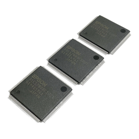
Epson S5U1C17001H2 User manual

Rev. 1.1
CMOS 16-BIT SINGLE CHIP MICROCONTROLLER
S5U1C17001H2 User Manual
(ICDmini Ver2.0)

Evaluation board/kit and Development tool important notice
1. This evaluation board/kit or development tool is designed for use for engineering evaluation, demonstration,
or development purposes only. Do not use it for other purpose. It is not intended to meet the requirement of
design for finished product.
2. This evaluation board/kit or development tool is intended for use by an electronics engineer, and it is not the
product for consumer. The user should use this goods properly and safely. Seiko Epson dose not assume any
responsibility and liability of any kind of damage and/or fire coursed by usage of it. User should cease to use
it when any abnormal issue occurs even during proper and safe use.
3. The part used for this evaluation board/kit or development tool is changed without any notice.
NOTICE
No part of this material may be reproduced or duplicated in any form or by any means without the written
permission of Seiko Epson. Seiko Epson reserves the right to make changes to this material without notice.
Seiko Epson does not assume any liability of any kind arising out of any inaccuracies contained in this material
or due to its application or use in any product or circuit and, further, there is no representation that this material is
applicable to products requiring high level reliability, such as, medical products. Moreover, no license to any
intellectual property rights is granted by implication or otherwise, and there is no representation or warranty that
anything made in accordance with this material will be free from any patent or copyright infringement of a third
party. This material or portions thereof may contain technology or the subject relating to strategic products
under the control of the Foreign Exchange and Foreign Trade Law of Japan and may require an export license
from the Ministry of Economy, Trade and Industry or other approval from another government agency.
All brands or product names mentioned herein are trademarks and/or registered trademarks of their respective
companies.
©SEIKO EPSON CORPORATION 2011,All rights reserved.

Configuration of product number
Devices
S1 C17xxx F 00E1 00
Development tools
S5U1 C 17000 Y2 1 00
Packing specifications
00 : Besides tape & reel
0A : TCP BL 2 directions
0B : Tape & reel BACK
0C : TCP BR 2 directions
0D : TCP BT 2 directions
0E : TCP BD 2 directions
0F : Tape & reel FRONT
0G: TCP BT 4 directions
0H : TCP BD 4 directions
0J : TCP SL 2 directions
0K : TCP SR 2 directions
0L : Tape & reel LEFT
0M: TCP ST 2 directions
0N : TCP SD 2 directions
0P : TCP ST 4 directions
0Q: TCP SD 4 directions
0R : Tape & reel RIGHT
99 : Specs not fixed
Specification
Package
[D: die form; F: QFP, B: BGA]
Model number
Model name
[C: microcomputer, digital products]
Product classification
[S1: semiconductor]
Packing specifications
[00: standard packing]
Version
[1: Version 1]
Tool type
Hx : ICE
Dx : Evaluation board
Ex : ROM emulation board
Mx: Emulation memory for external ROM
Tx : A socket for mounting
Cx : Compiler package
Sx : Middleware package
Yx : Writer software
Corresponding model number
[17xxx: for S1C17xxx]
Tool classification
[C: microcomputer use]
Product classification
[S5U1: development tool for semiconductor products]

S5U1C17001H2 User Manual Seiko Epson Corporation i
(ICDmini Ver2.0) (Rev2.0)
Table of Contents
1. Overview..................................................................................................................... 1
1.1 Features....................................................................................................................................2
1.2 Operating Environment...........................................................................................................3
2. Components Included with Package........................................................................ 4
3. Name and Function of Each Part.............................................................................. 5
3.1 Left Side Panel.........................................................................................................................5
3.1.1 4-pin Target Interface Connector (black).............................................................................5
3.1.2 4-pin Flash Programming Power Supply Connector (white)................................................5
3.1.3 DIP Switch ..........................................................................................................................6
3.1.4 BRK IN Pin..........................................................................................................................8
3.1.5 GND Pin..............................................................................................................................8
3.1.6 3.3 V Output Pin..................................................................................................................8
3.1.7 1.8 V Output Pin..................................................................................................................8
3.2 Right Side Panel ......................................................................................................................9
3.2.1 USB Connector...................................................................................................................9
3.3 Top Panel................................................................................................................................10
3.3.1 LED...................................................................................................................................10
3.3.1.1 In ICD mode ......................................................................................................................................10
3.3.1.2 In Flash programmer mode ...............................................................................................................11
3.3.2 RESET/RESTART Switch.................................................................................................13
4. Connections............................................................................................................. 14
4.1 Connecting the Target System .............................................................................................14
4.1.1 Target Interface Connector................................................................................................14
4.1.1.1 Connecting to the S1C33 processor 10-pin connector......................................................................15
4.1.2 Flash Programming Power Supply Connector..................................................................16
4.1.2.1 Target reset signal output (TARGET RST OUT)................................................................................16
4.1.2.2 Target voltage input (TARGET VCC IN).............................................................................................16
4.1.2.3 Flash programming voltage output (FLASH VCC OUT) ....................................................................17
4.2 Connecting to the Host Computer........................................................................................18
4.2.1 USB Driver Locations........................................................................................................18
4.2.2 USB Driver Installation Procedure.....................................................................................18
5. ICD Mode .................................................................................................................. 20
5.1 Specifying ICD Mode .............................................................................................................20
5.2 Activation in ICD Mode..........................................................................................................20
5.2.1 When the TARGET RST OUT Signal is Not Connected....................................................20
5.2.2 When the TARGET RST OUT Signal is Connected ..........................................................21
5.3 Starting Up the Debugger...................................................................................................... 21
5.4 Flash Programming Voltage Setting .................................................................................... 22
6. Flash Programmer Mode......................................................................................... 23
6.1 Preparation for Using Flash Programmer Mode ................................................................. 23
6.1.1 fwlp Command.................................................................................................................. 23
6.1.1.1 Command format...............................................................................................................................23
6.1.1.2 Command setting example................................................................................................................25
6.1.2 fwld Command.................................................................................................................. 25
6.1.2.1 Command format...............................................................................................................................25

ii Seiko Epson Corporation S5U1C17001H2 User Manual
(ICDmini Ver2.0)
6.1.2.2 Command setting example................................................................................................................25
6.2 Operations in Flash Programmer Mode...............................................................................26
7. Firmware Update...................................................................................................... 28
8. Precautions .............................................................................................................. 31
8.1 Restrictions on Debugging...................................................................................................31
8.2 Differences from the Actual IC..............................................................................................32
8.3 Notes on Use of S5U1C17001H ............................................................................................32
8.4 Differences between the S5U1C17001H and S5U1C33001H.............................................. 33
9. Troubleshooting....................................................................................................... 34
10. Specifications........................................................................................................... 35
10.1 Electrical Characteristics......................................................................................................35
Appendix......................................................................................................................... 36
Initial Validation when Designing a Target System...................................................................... 36
Revision History............................................................................................................. 38

S5U1C17001H2 User Manual Seiko Epson Corporation iii
(ICDmini Ver2.0) (Rev2.0)
Explanation of Terms (various modes)
S5U1C17001H (ICDmini)
ICD mode Flash programmer mode
This mode is for debugging the target system.
Debugging requires a host computer and the debugger
gdb (included in the S5U1C17001C S1C17 Family C
Compiler Package).
This mode is for programming the target system without
using a host computer.
Before programming can be performed, the program to
be written must be saved to the S5U1C17001H (ICDmini)
in ICD mode.
Debugger gdb (included in the S5U1C17001C S1C17 Family C Compiler Package)
Connect mode
Simulator (SIM) mode ICD Mini mode
The simulator mode simulates the target program
execution on the host computer memory and no other
tools are not required. However, the debug functions
depending on the ICD cannot be used.
This is the mode to debug the target program using the
S5U1C17001H (ICDmini) or S5U1C17002H (ICD board).
The program will be executed on the target system. The
S5U1C17001H (ICDmini) must be used in this mode.
Target (S1C17xxx)
Normal mode Debug mode
The normal mode is the normal state while the target
system is executing the user program.
The target enters debug mode by one of the conditions
shown below.
When a beak condition set by the debugger (gdb) has
met
When the break button on the gdb window is clicked
while the debugger (gdb) is connected to the target
When a low level signal is input to the DSIO pin of the
target system
When the CPU executes the brk instruction
In this mode, the target system accepts the control by the
debugger (gdb).
Various debugging operations, such as display and
rewriting the registers/memory, can be performed.
The target enters this mode when executing the startup
sequence after connecting it to the S5U1C17001H
(ICDmini).

1. Overview
S5U1C17001H2 User Manual Seiko Epson Corporation 1
(ICDmini Ver2.0) (Rev2.0)
1. Overview
The S5U1C17001H (ICDmini) is a hardware tool (emulator) that allows software to be efficiently developed for
the S1C17 Family of 16-bit processors and S1C33 Family of 32-bit processors. The S5U1C17001H is used to
connect the S1C17 or S1C33 processor on the target system to the debugger (gdb). It provides a development
environment for S1C17 and S1C33 Family software together with a debugger. It can also be used as a Flash
programmer to program the Flash memory built into the processor on the target system.
This manual primarily explains how to use the S5U1C17001H. For details on the debugger (gdb) functions and
commands, refer to the “S5U1C17001C Manual (C Compiler Package for S1C17 Family)” or “S5U1C33001C
Manual (C Compiler Package for S1C33 Family).”
Figure 1.1 S5U1C17001H External View
Note: Do not open the case as it may cause a malfunction.
This manual applies to the following.
S5U1C17001H2100 (ICDmini ver2.0)
S5U1C17001H S1C17 firmware ver3.2, S1C33 firmware ver1.5*1
*1: Products may be shipped installed with later versions than those indicated above, due to subsequent version
upgrades.
Precautions before using the S5U1C17001H
Please read the sections shown below before getting started with the S5U1C17001H.
These sections, especially (2) and (3), describe the answers to frequently asked questions.
(1) Chapter 2, Components Included with Package
Make sure all of the listed items are included with your package.
(2) Section 4.2, Connecting to the Host Computer
Install the USB driver before the S5U1C17001H can be used.
(3) Section 4.1, Connecting the Target System
Please pay particular attention to the Notes.

1. Overview
2 Seiko Epson Corporation S5U1C17001H2 User Manual
(ICDmini Ver2.0)
1.1 Features
Table 1.1.1 Features
S1C17 processor S1C33 processor
Cores supported
S1C17 Core S1C33 STD Core
S1C33 mini Core
S1C33 PE Core
S1C33 ADV Core
Host interface
USB 1.1
Debugger (gdb) mode
ICD Mini mode ICD6 mode
Program break functions
PC break function
Lapse of time break function
Forced break function
External forced break function (BRK IN pin input)
PC break function
Lapse of time break function
Forced break function
External forced break function (BRK IN pin input)
Area break function
Bus break function
(Selectable logical/physical address)
Data break function
Trace function
Not available
Measurement of target program execution time
Can be measured between 3 s and 6515 hours In second units: 3 µs to 36 minutes
In s units: 3 s to 1.8 minutes
Cycle counting function
Not available Available
Standalone Flash programmer function
Available
Firmware update function
Available
DCLK frequency to communicate with the target *1
4 kHz to 40 MHz*2 4 kHz to 40 MHz
Flash programming power voltage supply
Available
Variable voltage output: 6.0 V to 8.0 V (max. 100 mA) Available
Fixed voltage output: 7.0 V (max. 100 mA)
Target reset signal output
Available
Target system I/O interface voltage
3.3 V, 1.8 V, or voltage input from target (1.0 V to 5.5 V)
Target system interface connector
4-pin connector*3
Flash programming power supply connector
4-pin connector
*1: Clock frequency output from the DCLK pin while in Debugging mode.
*2: Reference values for data download speed are published on the user’s site for each S1C processor model.
*3: If connecting a 10-pin connector, refer to “4.1.1.1 Connecting to S1C33 processor 10-pin connector.”

1. Overview
S5U1C17001H2 User Manual Seiko Epson Corporation 3
(ICDmini Ver2.0) (Rev2.0)
Table 1.1.2 Differences between S5U1C17001H Products
S5U1C17001H1100
(ICDmini Ver1.0) S5U1C17001H1200
(ICDmini Ver1.1) S5U1C17001H2100
(ICDmini Ver2.0)
S1C17 FW Ver1.0 or S1C17
FW Ver1.1 S1C17 FW Ver1.1 S1C17 FW Ver3.2Firmware (FW)
version as shipped S1C33 FW not supported S1C33 FW not supported S1C33 FW Ver1.5
Fixed 7.0 V voltage (max. 30
mA) output with S1C17
processor selected
Fixed 7.0 V voltage (max. 30
mA) output with S1C17
processor selected
Variable 6.0 V to 8.0 V
voltage (max. 100 mA)
output with S1C17
processor selected*1
Flash programming
voltage supply
Fixed 7.0 V voltage (max. 30
mA) output with S1C33
processor selected
Fixed 7.0 V voltage (max. 30
mA) output with S1C33
processor selected
Fixed 7.0 V voltage (max. 30
mA) output with S1C33
processor selected*1
Flash programming
voltage supply to Vpp
pin
Not supported Not supported Supported
Supported target
system I/O voltage 3.3 V, 1.8 V, or voltage input
from target (1.0 V to 5.0 V) 3.3 V, 1.8 V, or voltage input
from target (1.0 V to 5.5 V) 3.3 V, 1.8 V, or voltage input
from target (1.0 V to 5.5 V)
3.3 V (max. 100 mA) output
pin
Target system power
supply Not available Not available
1.8 V (max. 100 mA) output
pin
Flash programming
power supply cable
(with black connector)
Not available Not available Available
*1: Supported from S1C17 firmware Ver3.0 and S1C33 firmware Ver1.4 onward.
1.2 Operating Environment
As the host computer, the S5U1C17001H uses a PC with a USB port (USB 1.1) available.
For details concerning operating systems, refer to “Operating Environment” in the S5U1C17001C Manual.

2. Components Included with Package
4 Seiko Epson Corporation S5U1C17001H2 User Manual
(ICDmini Ver2.0)
2. Components Included with Package
The following shows the components included with the S5U1C17001H package:
(1) S5U1C17001H main unit..............................................1
(2) USB cable .....................................................................1
(3) Target interface cable (4-pin)........................................1
(4) Flash programming power supply cable (4-pin)...........2
(5) User registration card ........................................... English/Japanese, 1 each
(6) Warranty card ..................................................... English/Japanese, 1 each
(7) Usage precautions.........................................................English/Japanese, 1 each
(8) Manual download guide................................................English/Japanese, 1 each
The items specified below are not included with the package. These items must be prepared separately.
When developing an S1C17 application
S5U1C17001C (S1C17 Family C Compiler Package)
S1C17 Family debugger (gdb) included with package
S5U1C17001C Manual
Included with S1C17 Family C Compiler Package
When developing an S1C33 application
S5U1C33001C (S1C33 Family C Compiler Package)
S1C33 Family debugger (gdb) included with package
S5U1C33001C Manual
Included with S1C33 Family C Compiler Package
S5U1C17001H User Manual (ICDmini Ver2.0)
This manual can be downloaded from the Seiko Epson Electronic Devices website.
Figure 2.1 S5U1C17001H Package Contents

3. Name and Function of Each Part
S5U1C17001H2 User Manual Seiko Epson Corporation 5
(ICDmini Ver2.0) (Rev2.0)
3. Name and Function of Each Part
The following shows the name of each part of the S5U1C17001H.
3.1 Left Side Panel
Figure 3.1.1 Left Side Panel
3.1.1 4-pin Target Interface Connector (black)
This connector is used to input/output the debug signals (DCLK, DSIO, and DST2) from/to the S1C processor on
the target system. See Section 4.1.1, “Target Interface Connector,” for the pin assignment and connection.
3.1.2 4-pin Flash Programming Power Supply Connector (white)
This connector is used to output the reset signal to the target system and to supply a voltage for Flash
programming (Note).Also it is used to input the target operating voltage when the target system voltage level is
used for the debug signal interface. See Section 4.1.2, “Flash Programming Power Supply Connector,” for the pin
assignment and connection.
Note: The S5U1C17001H includes a Flash programming power supply
When S1C17 processor is selected
Use in conjunction with S5U1C17001C (GNU17 v2.0.0 or later) outputs a variable voltage of 6.0 V to 8.0 V
(max. 100 mA).
When S1C33 processor is selected
Setting SW8 to “On” outputs a fixed voltage of 7.0 V (max. 100 mA).
This must never be used with S1C processors for which usage instructions are not provided in the technical
manual when supplying a voltage as the Flash programming power supply from the S5U1C17001H to the target.
Otherwise, there is a risk of damaging the chip due to overvoltage. The VPP pin should be left open if a connector
pin is provided on the target board without using the Flash programming voltage.
BRK IN pin
(yellow) DIP switch
4-pin Flash programming
power supply connector (white) 4-pin target interface
connector (black)
1.8 V power supply
pin (orange) 3.3 V power
supply pin (red)
GND pin
(black)

3. Name and Function of Each Part
6 Seiko Epson Corporation S5U1C17001H2 User Manual
(ICDmini Ver2.0)
3.1.3 DIP Switch
The DIP switch assembly is used to select the target CPU core, Flash programmer mode, DSIO signal level,
connection test feature, firmware update feature, and Flash programming voltage output.
Figure 3.1.3.1 DIP Switch Assembly
Note: The changed switch settings will take effect after the RESET/START switch is pressed.
Selecting the target CPU core (SW1)
Table 3.1.3.1 SW1 Settings
SW1 Setting
OPEN () Target CPU is an S1C17xxx or a product in which the S1C17 Core is embedded (C17).
ON () Target CPU is an S1C33xxx or a product in which the S1C33 Core is embedded (C33).
Selecting either ICD Mode or Flash Programmer Mode (SW2 and SW3)
Table 3.1.3.2 SW2 and SW3 Settings
SW2 SW3 Setting
OPEN () OPEN () ICD mode (default)
ON () OPEN () Flash programmer mode Erase program
OPEN () ON () Flash programmer mode Verify
ON () ON () Flash programmer mode Erase program verify
ICD mode: Mode for executing debugging commands from the debugger on the host computer
For more information on this mode, refer to “5 ICD Mode.”
Flash programmer mode: The S5U1C17001H operates as a standalone Flash programmer.
For more information on this mode, refer to “6 Flash Programmer Mode.”
Selecting the DSIO signal level (SW4 and SW5)
Table 3.1.3.3 SW4 and SW5 Settings
SW4 SW5 Setting
OPEN () OPEN () 3.3 V (default)
OPEN () ON () 1.8 V
ON () – Voltage (1.0 to 5.5 V) input from the target
The target operating voltage should be input to Pin 4 on the Flash programming power supply connector.
Enabling the connection test (SW6)
Table 3.1.3.4 SW6 Settings
SW6 Setting
OPEN () Omit connection test (default)
ON () Execute connection test
The connection test is a communication diagnostic feature at start up of the debugger.

3. Name and Function of Each Part
S5U1C17001H2 User Manual Seiko Epson Corporation 7
(ICDmini Ver2.0) (Rev2.0)
Setting firmware update mode (SW7)
Table 3.1.3.5 SW7 Settings
SW7 Setting
OPEN () Connect to the target (default)
ON () Do not connect to the target
When SW7 is set to ON, a connection between the S5U1C17001H and the debugger (gdb) can be established
even if a target is not connected. See Chapter 7, “Firmware Update,” for how to update the firmware.
Enabling voltage output for Flash programming (SW8)
Table 3.1.3.6 SW8 Settings
SW8 Setting
OPEN () Stop Flash programming voltage (default)
ON () Output Flash programming voltage
Note: The S5U1C17001H includes a Flash programming power supply.
When S1C17 processor is selected
Use in conjunction with S5U1C17001C (GNU17 v2.0.0 or later) outputs a variable voltage of 6.0 V to 8.0 V
(max. 100 mA).
When S1C33 processor is selected
Setting SW8 to “On” outputs a fixed voltage of 7.0 V (max. 100 mA).
This must never be used with S1C processors for which usage instructions are not provided in the technical
manual when supplying a voltage as the Flash programming power supply from the S5U1C17001H to the target.
Otherwise, there is a risk of damaging the chip due to overvoltage.

3. Name and Function of Each Part
8 Seiko Epson Corporation S5U1C17001H2 User Manual
(ICDmini Ver2.0)
3.1.4 BRK IN Pin
In ICD mode, if a Low level signal is input to this pin when the target program is being executed, execution of
the target program is suspended. After a Low level is input to the BRK IN pin, a break will occur after a few
instructions have been executed.
With S1C17 processor selected
In Flash programmer mode, inputting a Low level to this pin has the same effect as pressing the RESET/
START switch (it starts erasing/writing/verification).
With S1C33 processor selected
In Flash programming mode: BRK IN pin does not function.
Note: The voltage to apply to the BRK IN pin must be 0 V for low level and 3.3 V or open for high level.
The BRK IN pin is always pulled up to 3.3 V.
3.1.5 GND Pin
Connect this pin to the GND level (0 V).
3.1.6 3.3 V Output Pin
Pin capable of supplying a 3.3 V power supply (max. 100 mA) to the target system.
3.1.7 1.8 V Output Pin
Pin capable of supplying a 1.8 V power supply (max. 100 mA) to the target system.

3. Name and Function of Each Part
S5U1C17001H2 User Manual Seiko Epson Corporation 9
(ICDmini Ver2.0) (Rev2.0)
3.2 Right Side Panel
Figure 3.2.1 Right Side Panel
3.2.1 USB Connector
This connector is used to connect to a host computer using the supplied USB cable.
Note: When a bus-powered USB hub is used to connect the S5U1C17001H to the host computer, there may be a
shortage of drive power. Especially if supplying the flash programming voltage, either connect directly to
the host computer’s USB port, or use anAC adapter (with USB 5 V output) capable of supplying power to
the USB cable.
If using an AC adapter, set the S5U1C17001H mode to be used and confirm beforehand that erasing and
writing is possible as desired.
USB connector

3. Name and Function of Each Part
10 Seiko Epson Corporation S5U1C17001H2 User Manual
(ICDmini Ver2.0)
3.3 Top Panel
Figure 3.3.1 Top Panel
3.3.1 LED
The four LEDs located on the top panel indicate debugging and Flash programming statuses.
The indicated status differs between ICD mode and Flash programmer mode.
3.3.1.1 In ICD mode
LED1 (CPU)
This LED indicates the target CPU selected using SW1.
Table 3.3.1.1.1 LED1 Status
S1C17 S1C33 LED status Status
– (blue) Target CPU is an S1C17xxx or a product in which the S1C17 Core is embedded
(C17).
– (green) Target CPU is an S1C33xxx or a product in which the S1C33 Core is embedded
(C33).
LED2 (ICD MODE)
Illuminates as shown below when ICD mode is selected using SW2 and SW3.
Table 3.3.1.1.2 LED2 Status
S1C17 S1C33 LED status Status
(blue) The S5U1C17001H is being operated in ICD mode.
RESET/START switch

3. Name and Function of Each Part
S5U1C17001H2 User Manual Seiko Epson Corporation 11
(ICDmini Ver2.0) (Rev2.0)
LED3 (EMU)
This LED lights when the target program is started from the debugger to indicate that the target system is
executing the target program. Also this LED lights when the target system is in power-off status or it is not
connected. In this case, the LED will go out by turning the target system on or by pressing the RESET/ START
switch after connecting the target system properly.
Table 3.3.1.1.3 LED3 Status
S1C17 S1C33 LED status Status
The target system is in power-off status.
The target system is not connected properly.
(red)
The target system is executing the user program.
(out) Other
LED4 (DBG)
This LED indicates that the target S1C processor is placed in debug mode.
Table 3.3.1.1.4 LED4 Status
S1C17 S1C33 LED status Status
(green) The target S1C processor is placed in debug mode.
Also this LED rights with LED3 before the initial connection between the
S5U1C17001H and the target S1C processor has been established.
(out) Other
: Supported
– : Not supported
3.3.1.2 In Flash programmer mode
When the S5U1C17001H starts up in Flash programmer mode, LED2 lights in white (), LED3 lights in
magenta (), or LED4 lights in yellow ().
LED1 (CPU)
This LED indicates the target CPU selected using SW1.
Table 3.3.1.2.1 LED1 Status
S1C17 S1C33 LED status Status
– (blue) Mode for products with embedded S1C17xxx or S1C17 Core (C17)
– (green) Mode for products with embedded S1C33xxx or S1C33 Core (C33)
LED2 (ERASE)
This LED indicates a Flash erasing selection/operation status.
Table 3.3.1.2.2 LED2 Status
S1C17 S1C33 LED status Status
(white) The Flash erasing function is selected.
(blinking
white) The Flash memory is being erased.
(green) The Flash erasing operation has completed normally. (OK)
(red) A Flash erase error has occurred. (ERR)

3. Name and Function of Each Part
12 Seiko Epson Corporation S5U1C17001H2 User Manual
(ICDmini Ver2.0)
LED3 (WRITE)
This LED indicates a Flash programming selection/operation status.
Table 3.3.1.2.3 LED3 Status
S1C17 S1C33 LED status Status
The Flash programming function is selected.(magenta) Write-back execution option setting
The Flash memory is being programmed.(blinking
magenta) Write-back operation in progress
The Flash programming operation has completed normally. (OK)(green) Write-back completed successfully. (OK)
* Blinks when flash programmer mode non-execution option (-n) is set.
A Flash program error has occurred. (ERR)(red) Write-back completed successfully. (OK)
LED4 (VERIFY)
This LED indicates a Flash verification selection/operation status.
Table 3.3.1.2.4 LED4 status
S1C17 S1C33 LED status Status
The Flash verification function is selected.(yellow) Write-back execution option setting
The Flash memory is being verified.(blinking
yellow) Write-back operation in progress
The Flash verify operation has completed normally. (OK)(green) Write-back completed successfully. (OK)
* Blinks when flash programmer mode non-execution option (-n) is set.
A Flash verify error has occurred. (ERR)(red) Write-back completed successfully. (OK)
Table 3.3.1.2.5 Other Errors
LED status
S1C17 S1C33 LED1 LED2 LED3 Status
–
(blinking
red)
(blinking
red)
(blinking
magenta)
Flash programming voltage setting error (ERR)
The error conditions are one of the following.
(1) “-v” option was set by the “fwlp” command, but SW8 is open.
(2) “-v” option was not set by the “fwlp” command, but SW8 is on.
(3) “-v” option was set by the “fwlp” command, but the setting
was out of range or not input.
(4) “-v” option was set multiple times by the “fwlp” command.
–
(blinking
red)
(blinking
red)
(blinking
white)
Flash programming voltage output failure (ERR)
Flash programming voltage setting processing failed in
S5U1C17001H.
–
(blinking
red)
(blinking
red)
(blinking
blue)
Communication packet size setting error (ERR)
(1) “-s” option was set by the “fwlp” command, but the setting
was out of range or not input.
(2) “-s” option was set multiple times by the “fwlp” command.
–
(blinking
red)
(blinking
red)
(blinking
yellow)
Write-back setting error (ERR)
(1) “-b” option was set by the “fwlp” command, but the setting

3. Name and Function of Each Part
S5U1C17001H2 User Manual Seiko Epson Corporation 13
(ICDmini Ver2.0) (Rev2.0)
was out of range or not input.
(2) “-b” option was set multiple times by the “fwlp” command.
–
(blinking
red)
(blinking
yellow)
(blinking
red)
Flash programmer non-execution (erase, write, verify) setting
error (ERR)
(1) “-n” option was set by the “fwlp” command, but a text string
was set.
(2) “-n” option was set multiple times by the “fwlp” command.
–
(blinking
red)
(blinking
red)
(blinking
red)
Flash programmer non-execution (erase, write, verify) setting
error (ERR)
Write-back execution option (-b) was not set.
–
(blinking
red)
(blinking
blue)
(blinking
red)
Timeout setting error (ERR)
(1) “-t” option was set by the “fwlp” command, but the setting was
out of range or not input.
(2) “-t” option was set multiple times by the “fwlp” command.
: Supported
– : Not supported
3.3.2 RESET/RESTART Switch
The function differs between ICD mode and Flash programmer mode.
In ICD mode
Click:
The firmware restarts and performs the initial sequence for connecting with the S1C processor on the target
system. If the target board has not been connected physically, the S5U1C17001H enters initial connection
waiting status.
When the TARGET RST OUT signal of the S5U1C17001H has been connected to the target system, a reset
signal is output to the target system simultaneously.
In Flash programmer mode
Click:
The S5U1C17001H starts the selected Flash operation (erasing, programming, verification).
If the LED for the operation to be executed indicates OK or ERR, a hardware reset will return to default state.
The S5U1C17001H is subjected to a hardware reset while the Flash programmer is operating.
Press and hold (about three seconds):
Issues a hardware reset to the S5U1C17001H.
Note: When a DIP switch setting is changed, it will take effect by pressing the RESET/START switch (in both
ICD and Flash programmer modes).

4. Connections
14 Seiko Epson Corporation S5U1C17001H2 User Manual
(ICDmini Ver2.0)
4. Connections
4.1 Connecting the Target System
4.1.1 Target Interface Connector
The 4-pin target interface connector (black) on the S5U1C17001H is used to input/output the debug signals
from/to the S1C processor on the target system. Use the target interface cable attached to the S5U1C17001H to
connect between this connector and the target system. This connection is always required to perform debugging.
The pin assignment of the 4-pin connector (black) on the S5U1C17001H is shown in the table below. For the
debug pin numbers on the S1C processor, refer to the technical manual of each model.
Table 4.1.1.1 Pin Assignment of the Target Interface Connector (Black)
No. Pin name I/O Pin function
1 DCLK I Clock signal input pin for debugging
2 GND – Power supply GND pin
3 DSIO I/O Serial transfer I/O pin for debugging
4 3 2 1
4 DST2 I Debug status signal input pin
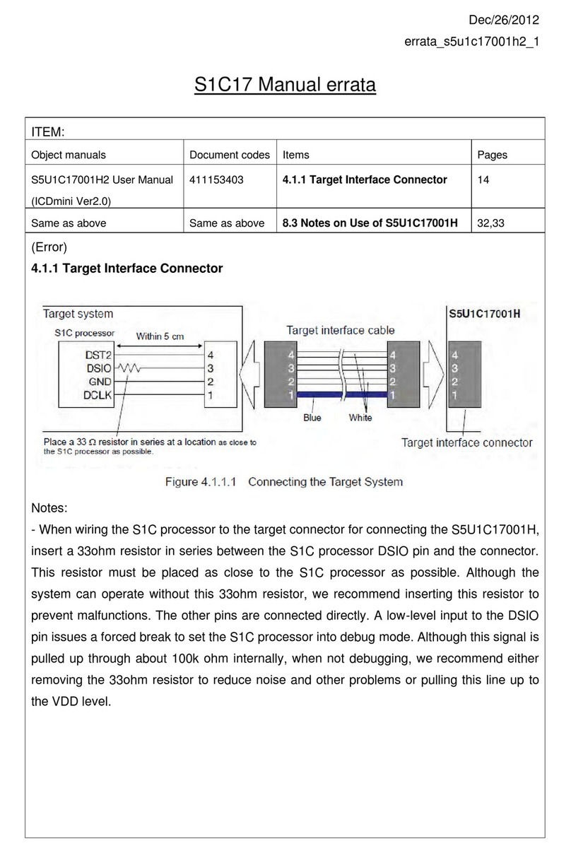
Figure 4.1.1.1 Connecting the Target System
Notes: Set the interface level (3.3 V/1.8 V/target input) using the DIP switches SW4 and SW5, and select the
CPU Core using the SW1 according to the target system before connecting the target system.
The signals connected to the S5U1C17001H are very high-speed signals, so the connector on the target
system must be mounted within 5 cm from the S1C processor. If there is more distance between the
connector and the S1C processor, the S5U1C17001H may not work properly.
When wiring the S1C processor to the target connector for connecting the S5U1C17001H, insert a
33 resistor in series between the S1C processor DSIO pin and the connector. This resistor must be
placed as close to the S1C processor as possible. Although the system can operate without this 33
resistor, we recommend inserting this resistor to prevent malfunctions. The other pins are connected
directly. Alow-level input to the DSIO pin issues a forced break to set the S1C processor into debug
mode. Although this signal is pulled up through about 100 kinternally, when not debugging, we
recommend either removing the 33 resistor to reduce noise and other problems or pulling this line up
to the VDD level.
Be sure to use the supplied 4-pin cable for connecting the target system to the S5U1C17001H. Using
another cable may cause a malfunction. If use of another cable is unavoidable, do not extend the target
interface cable, and connect the cable directly to the S5U1C17001H so that the distance to the S1C
processor on the target system is as short as possible (no more than 20 cm).
The 4-pin connector does not have a projection for preventing reverse insertion. Check the cable color
(blue) of pin 1 to be sure the insertion of connector is proper when connecting it to the target system.
Target system
Target interface cable
S1C processor
Within 5 cm
Target interface connector
Place a 33
resistor in series at a location
as close to
the S1C processor as possible.
Blue White
Table of contents
Other Epson Microcontroller manuals

Epson
Epson S1C17001 User manual

Epson
Epson S1C17624 User manual

Epson
Epson S1C33L26 User manual

Epson
Epson S5U1C17000Y23 User guide

Epson
Epson S1C17W14 User manual

Epson
Epson S1C17W22 User manual

Epson
Epson S1C17W03 User manual

Epson
Epson S5U1C17611T2 User manual

Epson
Epson S1C31D50 Owner's manual

Epson
Epson S1C6S3N2 User manual

Epson
Epson S1C17M20 User manual

Epson
Epson S5U1C31001L1200 User manual

Epson
Epson S1C17M01 User manual

Epson
Epson S1C31W65 User manual

Epson
Epson S5U1C17564T1 User manual

Epson
Epson S1C17W15 User manual

Epson
Epson S1C17 Series User manual

Epson
Epson Arm S1C31 Series User manual

Epson
Epson S1C17M10 User manual

Epson
Epson S1C31D50 User manual