10
P271Z
CLEVER01: 230Vac, 50/60Hz
CLEVER01M: 125Vac, 50/60Hz
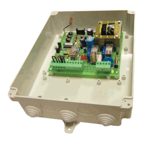
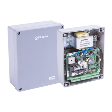
General connections
Complete the installation in line with low voltage regulations and applicable rules.
Use cables with sufficient section, always earthed.
Check the manufacturer's instructions for all the elements installed.
Make the connections with the power supply disconnected.
CONNECTIONS:
ANT Cable connectors for antenna
R.E. Connector for plug-in receiver
A.T. (ST1) Opening and closing key device
SG.C (FT1)Closing safety device
(photocell or mechanical strip)
AUX Output (24Vac, 350mA). Constant output in
order to feed peripheral devices
AOperator
COperator capacitor
MOperator motor
FCA Operator opening limit switch
FCC Operator closing limit switch
CONTROLS:
S1 Main switch
SW1 Radio code programming mini-pushbutton
RSD receiver (see “Radio code programming”
on page 11)
T.E Standby time regulation
(only functional in automatic mode)
Minimum value: 5 seconds,
Maximum value: 140 seconds
T.M. Operation time regulation
Minimum value: 1 second,
Maximum value: 70 seconds
J2 Automatic/step-by-step closing mode switch
(see “Radio code programming” on page 11)
Limit switches (FCA, FCC)
OThe door stops at the end of the operation by way
of the FCA and FCC limit switches built into the
operator. It is therefore necessary to have FCC and
FCA and to duly adjust them (see the instructions
for the operator used).
Turning direction check
1Connect the electrical power supply and press A.T.
(ST1). The first operation carried out after
connecting the power supply is opening.
2If closing is to be carried out instead of opening,
interchange the cables connected to cable
connectors 9 and 10.
