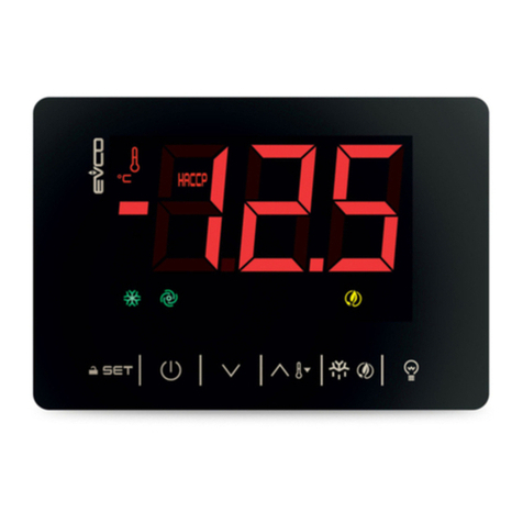
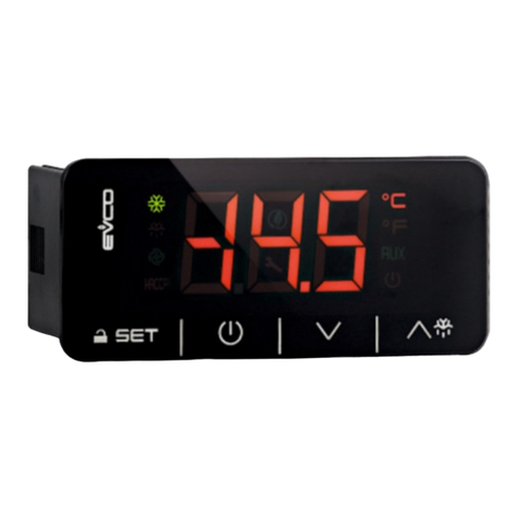
manuals.online logo
Brands
  1. Home
  2. •
  3. Brands
  4. •
  5. Evco
  6. •
  7. Controllers
  8. •
  9. Evco EVJ 200 Series User manual

Evco EVJ 200 Series User manual

EVCO S.p.A. | EVJ 200 | Instruction sheet ver. 2.0 | Code 104J200I203 | Pa e 1 of 4 | PT 18/17
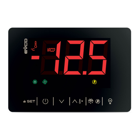
EVJ 200
Extra-large controllers for refrigerated cabinets and display units,
with energy-saving strategies
EN
ENG ISH
- Controllers for low temperature units.
- Power supply 230 VAC.
- Incorporated clock (accordin to the model).
- Cabinet probe and evaporator probe (PTC/NTC).
- Door switch input.
- Compressor relay 16 A res. @ 250 VAC or 30 A res. @ 250 VAC (accordin to the
model).
- Alarm buzzer.
- TTL MODBUS slave port for EVconnect APP or BMS.
- Port for SD card data-lo er module EVBD05 (accordin to the model).
- Models in plastic container or open-frame (accordin to the model).
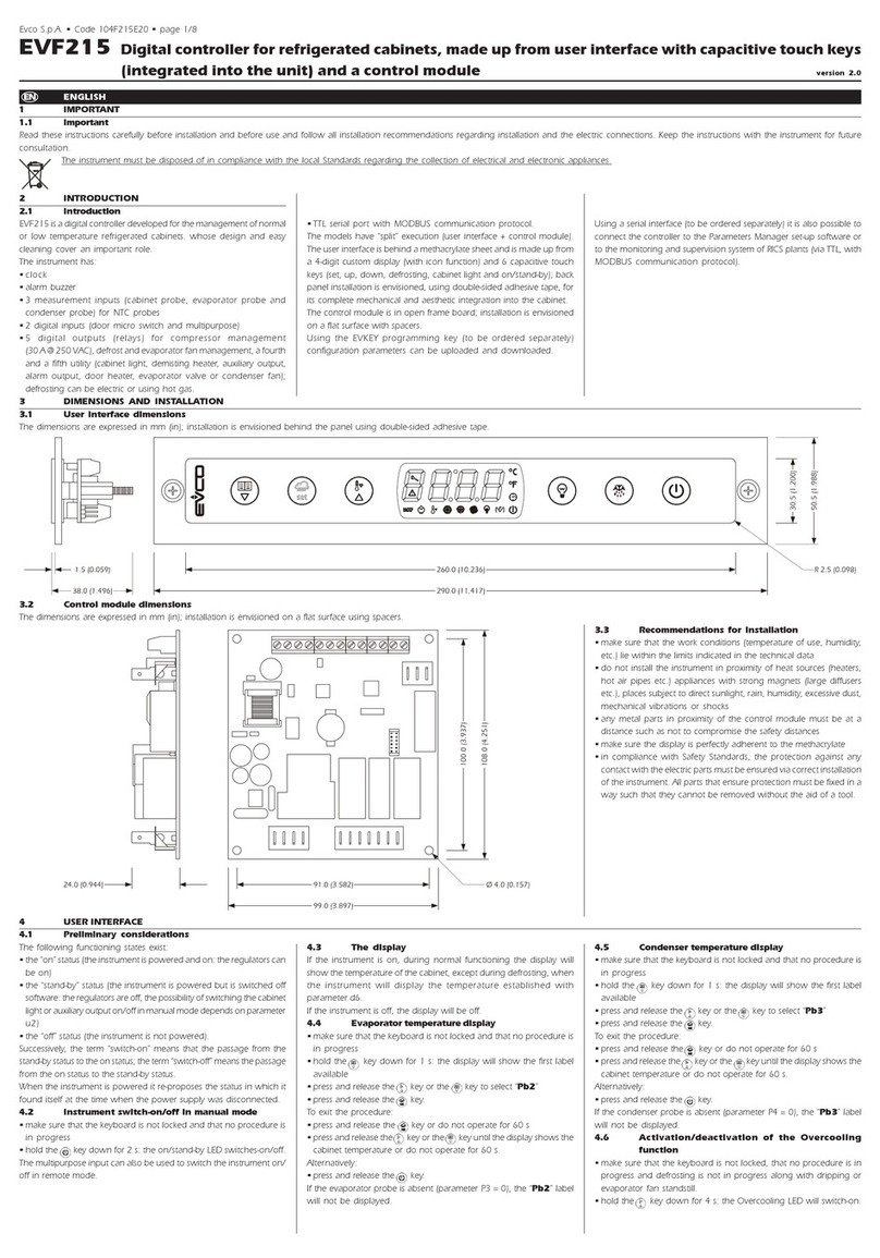
1 MEASUREMENTS AND INSTA ATION | Measurements in mm (inches)
1.1 Models in plastic container
Accordin to the model, front installation on a plastic or metal panel (with elastic holdin flaps)
or installed from behind a lass or methacrylate panel (with biadhesive) customizin the keys
on the front of the unit.
N.B.
For models for front installation: the thickness of a metal panel must be between
0.8 and 1.5 mm (1/32 and 1/16 in), while that for a plastic panel must be between
0.8 and 3.4 mm (1/32 and 1/8 in).
For models installed from behind: the thickness of the panel must be between
2.0 and 4.0 mm (1/16 and 1/8 in); the panel and the material used to make screen
printin must not contain conductive substances.
1.2 Open-frame models
To be installed from behind, with threaded studs and membrane keypad.
INSTALLATION PRECAUTIONS
- Ensure that the workin conditions are within the limits stated in the TECHNICAL
SPECIFICATIONS section.
- Do not install the device close to heat sources, equipment with a stron ma netic field,
in places subject to direct sunli ht, rain, damp, excessive dust, mechanical vibrations
or shocks.
- In compliance with safety re ulations, the device must be installed properly to ensure
adequate protection from contact with electrical parts. All protective parts must be
fixed in such a way as to need the aid of a tool to remove them.
2 E ECTRICA CONNECTION
N.B.
- Use cables of an adequate section for the current runnin throu h them.
- To reduce any electroma netic interference connect the power cables as far away
as possible from the si nal cables.
PRECAUTIONS FOR ELECTRICAL CONNECTION
- If usin an electrical or pneumatic screwdriver, adjust the ti htenin torque.
- If the device has been moved from a cold to a warm place, the humidity may have
caused condensation to form inside. Wait about an hour before switchin on the
power.
- Make sure that the supply volta e, electrical frequency and power are within the set
limits. See the section TECHNICAL SPECIFICATIONS.
- Disconnect the power supply before doin any type of maintenance.
- Do not use the device as safety device.
- For repairs and for further information, contact the EVCO sales network.
3 FIRST-TIME USE
1. Install followin the instructions iven in the section MEASUREMENTS AND
INSTALLATION.
2. Power up the device and an internal test will be run.
The test normally takes a few seconds, when it is finished the display will switch off.
3. Confi ure the device as shown in the section Setting configuration parameters.
Recommended confi uration parameters for first-time use.
PAR.
DEF.
PARAMETER
MIN... MAX.
SP 0.0 setpoint r1... r2
P0 1 probe type 0 = PTC 1 = NTC
P2 0 temperature unit of measurement 0 = °C 1 = °F
d1
0
defrost type
0 = electric 1 = hot as
2 = compressor stopped
Then check that the remainin settin s are appropriate; see the section
CONFI URATION PARAMETERS.
4. Disconnect the device from the mains.
5. Make the electrical connection as shown in the section ELECTRICAL CONNECTION
without powerin up the device.
6. For the connection in an RS-485 network connect the interface EVIF22TSX or
EVIF23TSX, to activate real time functions in EVJ203, EVJ204, EVJ205, EVJ224 and
EVJ225 connect the module EVIF23TSX, for recordin HACCP data in CSV format on SD
card connect the module EVBD05, to use the device with the Android APP EVconnect
connect the interface EVIF25TBX (or use EVJ214N7VXXRXV, EVJ234 or EVJ235); see
the relevant instruction sheets. If EVIF22TSX or EVIF23TSX is used, set
parameter b E to 0.
7. Power up the device.
4 USER INTERFACE AND MAIN FUNCTIONS
4.1 Switching the device on and off
1.
If POF = 1 (default), touch the ON/STAND-BY key for 2s.
If the device is switched on, the display will show the P5 value ("cabinet temperature" default);
if the display shows an alarm code, see the section ALARMS.
LED
ON
OFF
FLASHING
compressor on
compressor off
- compressor protection active
- setpoint bein set
evaporator fan on
evaporator fan off
evaporator fan stop active
cabinet li ht on
cabinet li ht off
cabinet li ht on by di ital input
AUX 1
auxiliary function 1 on
auxiliary function 1 off
- auxiliary function 1 on by di ital
input
- auxiliary function 1 delay active
AUX 2
auxiliary function 2 on
auxiliary function 2 off
- auxiliary function 2 on by di ital
input
- auxiliary function 2 delay active
defrost or pre-drip
active
-
- defrost delay active
- drippin active
- ener y savin active
- low consumption
active
-
-
view time
-
set date, time and day of the
current week
view temperature
-
overcoolin or overheatin active
HACCP
saved HACCP alarm
-
new HACCP alarm saved
alarm active
-
-
If Loc = 1 (default) and 30s have elapsed without the keys bein pressed, the display will show
the “ oc” label and the keypad will lock automatically.
4.2 Unlock keypad
Touch a key for 1s: the display will show the label “Un ”.
4.3 Set the setpoint (if r3 = 0, default)
Check that the keypad isn’t locked.
1.
Touch the SET key.
2.
Touch the UP or DOWN key within 15s to set the value within the
limits r1 and r2 (default “-40... 50”)
3.
Touch the SET key (or do not operate for 15s).
4.4 Activate manual defrost (if r5 = 0, default)
Check that the keypad is not locked and that overcoolin is not active.
1.
Touch the DEFROST key for 2s.
If P3 = 1 (default), defrost is activated provided that the evaporator temperature is lower than
the d2 threshold.
4.5 Cabinet light on/off (if u1c... u5c = 5)
1.
Touch the CABINET LIGHT key.
4.6 Button-operated load on/off (if u1c... u5c = 10 or 11)
1.
Touch the CABINET LIGHT key (for 2s if u1c... u5c = 5).
If u1c... u5c = 6, the demisting switch on for the u6 duration.
4.7 Silence buzzer (if u9 = 1, default)
Touch a key.
If u1c... u5c = 11 and u4 = 1, the alarm output is deactivated.
5 ADDITIONA FUNCTIONS
5.1 Activate/deactivate overcooling and overheating
Check that the keypad is not locked.
1.
Touch the UP key for 2s.
FUNCTION CONDITION CONSEQUENCE
overcoolin
r5 = 0 and defrost not
active
the setpoint becomes “setpoint -
r6”, for the r7 duration
overheatin
r5 = 1
the setpoint becomes “setpoint +
r6”, for the r7 duration
5.2 Activate/deactivate energy saving in manual mode (if r5 = 0)
Check that the keypad is not locked.
1.
Touch the DEFROST key.
The setpoint becomes “setpoint + r4”, at maximum for HE2 duration.
5.3 Activate the high or low humidity functions (if F0 = 5)
Check that the keypad isn’t locked.
1.
Touch the DOWN key for 1s.
2.
Touch the UP or DOWN key within 15s to select the label “rH”.
3.
Touch the SET key for 2s until the display shows the ri ht label
for the function (only touch the key to see the function
activated).
LAB.
DESCRIPTION
rh
low humidity function (evaporator fan with F17 and F18 if the compressor is
off, on if the compressor is on)
rhH
hi h humidity function (evaporator fan on)
4.
Touch the ON/STAND-BY key (or do not operate for 60s) to exit
the procedure.
5.4 View/delete HACCP alarm information (not available in EVJ203, EVJ204,
EVJ205, EVJ224 and EVJ225)
Check that the keypad isn’t locked.
1.
Touch the DOWN key for 1s.
EVCO S.p.A. | EVJ 200 | Instruction sheet ver. 2.0 | Code 104J200I203 | Pa e 2 of 4 | PT 18/17
2.
Touch the UP or DOWN key within 15s to select a label.
LAB.
DESCRIPTION
S view HACCP alarm information
r S
delete HACCP alarm information
3.
Touch the SET key.
4.
Touch the UP or DOWN key to select an alarm code (to select
label “ S”) or to set “149” (to select label “r S”).
COD.
DESCRIPTION
A low temperature alarm
AH
hi h temperature alarm
id
open door alarm (if i4 = 1)
PF
power failure alarm (available in EVJ213, EVJ214, EVJ214N7VXXRXV, EVJ215,
EVJ234 and EVJ235 or in EVJ203, EVJ204, EVJ205, EVJ224 and EVJ225 with
interface EVIF25TBX connected)
5. Touch the SET key.
6.
Touch the ON/STAND-BY key (or do not operate for 60s) to exit
the procedure.
Example of alarm information (e. . a hi h temperature alarm).
8.0
critical value (calculated cabinet/product temperature)
was 8.0 °C/°F
Sta
(available in EVJ213, EVJ214, EVJ214N7VXXRXV, EVJ215, EVJ234
and EVJ235 or in EVJ203, EVJ204, EVJ205, EVJ224 and EVJ225 with
interface EVIF25TBX connected)
y15
alarm si nalled in 2015
n03
alarm si nalled in March
d26
alarm si nalled on 26 March 2015
h16
alarm si nalled at 16:00
n30
alarm si nalled at 16:30
dur
h01
alarm lasted 1h
n15
alarm lasted 1h 15min
5.5 View/delete compressor functioning hours
Check that the keypad isn’t locked.
1.
Touch the DOWN key for 1s.
2.
Touch the UP or DOWN key within 15s to select a label.
LAB.
DESCRIPTION
CH1
view compressor functionin hundreds of hours
CH2 view second compressor functionin hundreds of hours (if u1c... u5c = 1)
rCH delete compressor and second compressor functionin hours
3. Touch the SET key.
4.
Touch the UP or DOWN key to set “149” (to select rCH).
5.
Touch the SET key.
6.
Touch the ON/STAND-BY key (or do not operate for 60s) to exit
the procedure.
5.6 View the temperature detected by the probes
Check that the keypad isn’t locked.
1.
Touch the DOWN key for 1s.
2.
Touch the UP or DOWN key within 15s to select a label.
LAB.
DESCRIPTION
Pb1 cabinet temperature (if P4 = 0, 1 or 2)
inlet air temperature (if P4 = 3)
Pb2
evaporator temperature (if P3 = 1 or 2)
Pb3
auxiliary temperature (if P4 = 1, 2 or 3)
Pb4 calculated product temperature (CPT; if P4 = 3)
3. Touch the SET key.
4.
Touch the ON/STAND-BY key (or do not operate for 60s) to exit
the procedure.
6
DATA- OGGER MODU E on SD CARD (not available in
EVJ203, EVJ204, EVJ205,
EVJ224 and EVJ225)
6.1 Initial information
The data-lo er module makes it possible to write information about the device on an SD card
(in CSV format ), in HACCP or service mode.
Data-lo er module confi uration parameters.
PAR.
DEF.
PARAMETER
MIN... MAX.
Sd0
30
SD card writin interval in HACCP
mode
1... 30 min
Sd1
1
SD card writin interval in service
mode
1... 30 min
Sd2 60 service mode duration 1... 240 min
Sd3 0 enable critical temperature recordin 0 = no 1 = yes
Sd4 1 enable cabinet temperature recordin 0 = no 1 = yes
Sd5 1 decimal separator type 0 = comma 1 = point
6.2 Writing in HACCP mode
Writin in HACCP mode is always activated, it enerates a daily file and a monthly file.
Information written in HACCP mode.
- cabinet temperature (if Sd4 = 1, default “no”)
- critical temperature (if Sd3 = 1, default “no”)
- device switched on/off
- defrost activated/completed
- ener y savin activated/deactivated
- alarm activated/restored
- power supply restored
The date and time is written for each piece of information.
6.3 Writing in service mode
Writin in service mode must be manually activated.
Information written in service mode.
- temperature detected by all probes
- enable/disable probes
- device switched on/off
- functions on/off
- defrost activated/completed
- ener y savin activated/deactivated
- alarm activated/restored
- power supply restored
The date and time is written for each piece of information.
6.4 Activate/deactivate writing in service mode
Check that the keypad isn’t locked.
1.
Touch the DOWN key for 1s.
2.
Touch the UP or DOWN key within 15s to select the label “SEr”.
3.
Touch the SET key.
4.
Touch the UP or DOWN key within 15s to set “1” (activate
writin ) or “0” (deactivate writin ).
5.
Touch the ON/STAND-BY key (or do not operate for 60s) to exit
the procedure.
6.5 File names
Example of a daily file name written in HACCP mode (e. . the file “log001_2015_03_26.csv”).
001 the device address is 1 (parameter LA)
2015 the file was written in 2015
03 the file was written in March
26 the file was written on 26 March 2015
Example of a monthly file name written in HACCP mode (e. . the file “log001_2015_m03.csv”).
001 the device address is 1 (parameter LA)
2015 the file was written in 2015
m03
the file was written in March 2015
Example of a file name written in service mode (e. . the file “log001_2015_0001.csv”).
001 the device address is 1 (parameter LA)
2015 the file was written in 2015
0001 sequence number
6.6 View data-logger module alarms
Check that the keypad isn’t locked.
1.
Touch the DOWN key for 1s.
2.
Touch the UP or DOWN key within 15s to select the label “Err”.
3.
Touch the SET key.
4.
Touch the UP or DOWN key within 15s to see the alarm code.
LAB. DESCRIPTION
FU
no space left on SD card alarm
Sd
SD card not inserted or not reco nised alarm
5.
Touch the ON/STAND-BY key (or do not operate for 60s) to exit
the procedure.
7 SETTINGS
7.1 Setting configuration parameters
1.
Touch the SET key for 4s: the display will show the label “PA”.
2.
Touch the SET key.
3.
Touch the UP or DOWN key within 15s to set the PAS value
(default “-19”).
4.
Touch the SET key (or do not operate for 15s): the display will
show the label “SP”.
5.
Touch the UP or DOWN key to select a parameter.
6.
Touch the SET key.
7.
Touch the UP or DOWN key within 15s to set the value.
8.
Touch the SET key (or do not operate for 15s).
9.
Touch the SET key for 4s (or do not operate for 60s) to exit the
procedure.
7.2 Set the date, time and day of the week (available in EVJ213, EVJ214,
EVJ214N7VXXRXV, EVJ215, EVJ234 and EVJ235 or in EVJ203, EVJ204, EVJ205,
EVJ224 and EVJ225 with interface EVIF25TBX connected)
N.B.
- If the device is connected to the interface EVIF25TBX, do not disconnect the device
from the mains within two minutes since the settin of the time and day of the
week.
- If the device communicates with the APP EVconnect, the date, time and day of the
week will automatically be set by the smartphone or tablet.
Check that the keypad isn’t locked.
1.
Touch the DOWN key for 1s.
2.
Touch the UP or DOWN key within 15s to select the label “rtc”.
3.
Touch the SET key: the display will show the label “y” followed
by the last two fi ures of the year.
4.
Touch the UP or DOWN key within 15s to set the year.
5. Repeat actions 3 and 4 to set the next labels.
LAB.
MEANING OF THE NUMBERS FOLLOWING THE LABEL
n month (01… 12)
d day (01… 31)
h time (00… 23)
n
minutes (00… 59)
6.
Touch the SET key: the display will show the label for the day of
the week.
7.
Touch the UP or DOWN key within 15s to set the day of the
week.
LAB.
DESCRIPTION
Mon Monday
tuE Tuesday
UEd Wednesday
thu
Thursday
Fri Friday
Sat Saturday
Sun Sunday
8. Touch the SET key: the device will exit the procedure.
9.
Touch the ON/STAND-BY key to exit the procedure beforehand.
7.3 Reset the factory settings
N.B.
Check that the factory settin s are appropriate; see the section CONFI URATION
PARAMETERS.
1.
Touch the SET key for 4s: the display will show the label “PA”.
2.
Touch the SET key.
3.
Touch the UP or DOWN key within 15s to set “149”.
4.
Touch the SET key (or do not operate for 15s): the display will
show the label “dEF”.
5.
Touch the SET key.
6.
Touch the UP or DOWN key within 15s to set “1”.
7.
Touch the SET key (or do not operate for 15s).
8. Interrupt the power supply to the device.
9.
Touch the SET key for 2s before action 6 to exit the procedure
beforehand.
8 CONFIGURATION PARAMETERS
N. PAR. DEF. SETPOINT MIN... MAX.
1 SP 0.0 setpoint r1... r2
N. PAR. DEF. ANALOGUE INPUTS MIN... MAX.
2
CA1
0.0
cabinet probe offset
-25... 25 °C/°F
if P4 = 3, air in probe offset
3 CA2 0.0 evaporator probe offset -25... 25 °C/°F
4 CA3 0.0 auxiliary probe offset -25... 25 °C/°F
5 P0 1 probe type 0 = PTC 1 = NTC
6 P1 1 enable °C decimal point 0 = no 1 = yes
7
P2
0
temperature unit of
measurement
0 = °C 1 = °F
8
P3
1
evaporator probe function
0 = disabled
1 = defrost + fan
2 = fan
9
P4
0
confi urable input function
(option 4 only available in
EVJ224, EVJ225, EVJ234 and
EVJ235)
0 = di ital input
1 = condenser probe
2 =
critical temperature probe
3 = air out probe
4 = evaporator 2 probe
if P4 = 3, re ulation temperature
= product temperature (CPT)
10
P5
0
value displayed
0 = re ulation temperature
1 = setpoint
2 = evaporator temperature
3 = auxiliary temperature
4 = air in temperature
11
P7
50
inlet air wei ht for calculated
product temperature (CPT)
0... 100 %
CPT = {[(P7 x (inlet air T)] +
[(100 - P7) x (outlet air T)] :
100}
12
P8 5 display refresh time 0... 250 s : 10
N.
PAR.
DEF.
REGULATION
MIN... MAX.
13
r0
2.0
setpoint differential
1... 15 °C/°F
if u1c... u5c 1, proportional
band
14
r1 -40 minimum setpoint -99 °C/°F... r2
15
r2 50.0
maximum setpoint r1... 199 °C/°F
16
r3 0 enable setpoint block
0 = no 1 = yes
17
r4 0.0 setpoint offset in ener y savin 0... 99 °C/°F
18
r5
0
coolin or heatin operation
0 = coolin
1 = heatin
19
r6
0.0
setpoint offset in
overcoolin /overheatin
0... 99 °C/°F
20
r7 0 overcoolin /overheatin duration 0... 240 min
21
r12
1
position of the r0 differential
0 = asymmetric
1 = symmetric
N. PAR. DEF. COMPRESSOR MIN... MAX.
22
C0
0
compressor on delay after
power-on
0... 240 min
23
C1
5
delay between 2 compressor
switch-ons
0... 240 min
24
C2 3 compressor off minimum time 0... 240 min
25
C3 0 compressor on minimum time 0... 240 s
26
C4
10
compressor off time durin
cabinet probe alarm
0... 240 min
27
C5
10
compressor on time durin
cabinet probe alarm
0... 240 min
28
C6
80.0
threshold for hi h condensation
warnin
0... 199 °C/°F
differential = 2 °C/4 °F
29
C7
90.0
threshold for hi h condensation
alarm
0... 199 °C/°F
30
C8 1 hi h condensation alarm delay 0... 15 min
31
C10
0
compressor hours for service
0... 999 h x 100
0 = disabled
32
C11 10 compressor 2 on delay 0... 240 s
33
C12
2
compressor hours wei ht for
balancin hours and switch-ons
(BHC) - (only available in
EVJ224, EVJ225, EVJ234 and
EVJ235)
0... 10
BHC = {[C12 x (compressor
hours)] + [C13 x
(compressor switch-ons)]}
34
C13
1
compressor hours switch-ons for
balancin hours and switch-ons
(BHC) - (only available in
EVJ224, EVJ225, EVJ234 and
EVJ235)
0... 10
BHC = {[C12 x (compressor
hours)] + [C13 x
(compressor switch-ons)]}
35
C14
1
tie between compressors (only
available in EVJ224, EVJ225,
EVJ234 and EVJ235)
0 = accordin to C11
1 = accordin to r0
N. PAR. DEF. DEFROST (if r5 = 0) MIN... MAX.
36
d0
8
automatic defrost interval
0... 99 h
0 = only manual
if d8 = 3, maximum interval
37
d1
0
defrost type
0 = electric
1 = hot as
2 = compressor stopped
38
d2 2.0 threshold for defrost end -99... 99 °C/°F
39
d3
30
defrost duration
0... 99 min
se P3 = 1, maximum duration
40
d4 0 enable defrost at power-on 0 = no 1 = yes
41
d5 0 defrost dealy after power-on 0... 99 min
42
d6
1
value displayed durin defrost
0 = re ulation temperature
1 = display locked
2 = dEF label
43
d7 2 drippin time 0... 15 min
44
d8
0
defrost interval countin mode
0 = device on hours
1 = compressor on hours
2 = hours evaporator
temperature < d9
3 = adaptive (if P4 = 4,
device on hours)
4 = real time
45
d9
0.0
evaporation threshold for
automatic defrost interval
countin
-99... 99 °C/°F
46
d11 0 enable defrost timeout alarm 0 = no 1 = yes
47
d15
0
compressor on consecutive time
for hot as defrost
0... 99 min
48
d16
0
pre-drippin time for hot as
defrost
0... 99 min
49
d18
40
adaptive defrost interval
0... 999 min
if compressor on + evapora-
tor temperature < d22
0 = only manual
50
d19
3.0
threshold for adaptive defrost
(relative to optimal evaporation
temperature)
0... 40 °C/°F
optimal evaporation
temperature - d19
51
d20
180
compressor on consecutive time
for defrost
0... 999 min
0 = disabled
52
d21
200
compressor on consecutive time
for defrost after power-on and
overcoolin
0... 500 min
if (re ulation temperature -
setpoint) > 10°C/20 °F
0 = disabled
53
d22
-2.0
evaporation threshold for
adaptive defrost interval countin
(relative to optimal evaporation
temperature)
-10... 10 °C/°F
optimal evaporation
temperature + d22
54
d25
0
enable air out probe for defrost
durin evaporator probe alarm
0 = no 1 = yes
55
d26
6
defrost interval durin
evaporator probe alarm
0... 99 h
0 = only manual
if d25 = 1
N.
PAR.
DEF.
ALARMS
MIN... MAX.
56
A0
0
select value for hi h/low
temperature alarms
0 = re ulation temperature
1 = evaporator temperature
57
A1
0.0
threshold for low temperature
alarm
-99... 99 °C/°F
58
A2
0
low temperature alarm type
0 = disabled
1 = relative to setpoint
2 = absolute
EVCO S.p.A. | EVJ 200 | Instruction sheet ver. 2.0 | Code 104J200I203 | Pa e 3 of 4 | PT 18/17
59
A4
0.0
threshold for hi h temperature
alarm
-99... 99 °C/°F
60
A5
0
hi h temperature alarm type
0 = re ulation temperature
1 = evaporator temperature
2 = auxiliary temperature
61
A6
120
hi h temperature alarm delay
after power-on
0... 240 min
62
A7
15
hi h/low temperature alarms
delay
0... 240 min
63
A8
15
hi h temperature alarm delay
after defrost
0... 240 min
64
A9
15
hi h temperature alarm delay
after door closin
0... 240 min
65
A10
10
power failure duration for alarm
recordin (not available in
EVJ203, EVJ204, EVJ205, EVJ224
and EVJ225)
0... 240 min
66
A11
2.0
hi h/low temperature alarms
reset differential
1... 15 °C/°F
67
A12
1
power failure alarm notification
type (not available in EVJ203,
EVJ204, EVJ205, EVJ224 and
EVJ225)
0 = HACCP LED
1 = HACCP LED + PF label +
buzzer
2 =
HACCP LED + PF label +
buzzer (if duration > A10)
N. PAR. DEF. FANS MIN... MAX.
68
F0
1
evaporator fan mode durin
normal operation
0 = off 1 = on
2 = on if compressor on
3 = thermore ulated (with
re ulation temperature
+ F1)
4 = thermore ulated (with
re ulation temperature
+ F1) if compressor on
5 = accordin to F6
6 =
thermore ulated (with F1)
7 = thermore ulated (with
F1) if compressor on
69
F1
-4.0
threshold for evaporator fan
operation
-99... 99 °C/°F
70
F2
0
evaporator fan mode durin
defrost and drippin
0 = off 1 = on
2 = accordin to F0
71
F3
2
evaporator fan off maximum
time
0... 15 min
def. 0 in EVJ203 ed EVJ213
72
F4
30
evaporator fan off time durin
ener y savin
0... 240 s x 10
if F0 ≠ 5
73
F5
30
evaporator fan on time durin
ener y savin
0... 240 s x 10
if F0 ≠ 5
74
F6
0
hi h/low humidity operation
0 = low humidity (with F17
and F18 if compressor
off, on if compressor on)
1 = hi h humifity (on)
75
F7
5.0
threshold for evaporator fan on
after drippin (relative to
setpoint)
-99... 99 °C/°F
setpoint + F7
76
F8
2.0
threshold for evaporator fan
operation differential
1... 15 °C/°F
77
F9
10
evaporator fan off delay after
compressor off
0... 240 s
if F0 = 2 or 5
78
F10
1
condenser fan mode
0 =
thermore ulated (with F11)
1 = thermore ulated (with
F11) if compressor off,
on if compressor on
2 = thermore ulated (with
F11) if compressor off,
on if compressor on, off
durin defrost, pre-
drippin and drippin
79
F11
15.0
threshold for condenser fan on
0... 99 °C/°F
differential = 2 °C/4 °F
80
F12
30
condenser fan off delay after
compressor off
0... 240 s
if P4 ≠ 1
81
F17
60
evaporator fan off time with low
humidity
0... 240 s
82
F18
10
evaporator fan on time with low
humidity
0... 240 s
N. PAR. DEF. DIGITAL INPUTS MIN... MAX.
83
i0
5
door switch input function
0 = disabled
1 = compressor +
evaporator fan off
2 = evaporator fan off
3 = cabinet li ht on
4 = compressor +
evaporator fan off,
cabinet li ht on
5 = evaporator fan off +
cabinet li ht on
84
i1
0
door switch input activation
0 = with contact closed
1 = with contact open
85
i2
30
open door alarm delay
-1... 120 min
-1 = disabled
86
i3
15
re ulation inhibition maximum
time with door open
-1... 120 min
-1 = until the closin
87
i4
0
enable open door alarm
recordin
0 = no 1 = yes
if i2 ≠ -1 and after i2
88
i5
8
multi-purpose input function
0 = disabled
1 = ener y savin
2 = iA alarm
3 = iSd alarm
4 =
button-operated load 1 on
5 =
button-operated load 2 on
6 = device on/off
7 = LP alarm
8 = C1t alarm
9 = C2t alarm
89
i6
0
multi-purpose input activation
0 = with contact closed
1 = with contact open
90
i7
0
multi-purpose input alarm delay
0... 120 min
if i5 = 3 or 7, compressor on
delay after alarm reset
91
i8
0
number of multi-purpose input
activations for hi h pressure
alarm
0... 15
0 = disabled
if i5 = 3
92
i9
240
reset counter time for hi h
pressure alarm
1... 999 min
93
i10
0
door closed consecutive time for
ener y savin
0... 999 min
after re ulation temperature
< SP
0 = disabled
94
i13
180
number of door openin s for
defrost
0... 240
0 = disabled
95
i14
32
door open consecutive time for
defrost
0... 240 min
0 = disabled
N. PAR. DEF. DIGITAL OUTPUTS MIN... MAX.
96
u1c
0
relay K1 confi uration (options
14 and 15 only available in
EVJ234 and EVJ235)
0 = first compressor
1 = second compressor
2 = evaporator fan
3 = condenser fan
4 = defrost
5 = cabinet li ht
6 = demistin
7 = door heaters
8 = heater for neutral zone
9 = drippin heater
10 = button-operated load 1
11 = button-operated load 2
12 = alarm
13 = on/stand-by
14 = evaporator fan 2
15 = defrost 2
97
u2c
4
relay K2 confi uration (options
14 and 15 only available in
EVJ234 and EVJ235)
0 = first compressor
1 = second compressor
2 = evaporator fan
3 = condenser fan
4 = defrost
5 = cabinet li ht
6 = demistin
7 = door heaters
8 = heater for neutral zone
9 = drippin heater
10 = button-operated load 1
11 = button-operated load 2
12 = alarm
13 = on/stand-by
14 = evaporator fan 2
15 = defrost 2
98
u3c
5
relay K3 confi uration (options
14 and 15 only available in
EVJ234 and EVJ235)
0 = first compressor
1 = second compressor
2 = evaporator fan
3 = condenser fan
4 = defrost
5 = cabinet li ht
6 = demistin
7 = door heaters
8 = heater for neutral zone
9 = drippin heater
10 = button-operated load 1
11 = button-operated load 2
12 = alarm
13 = on/stand-by
14 = evaporator fan 2
15 = defrost 2
99
u4c
2
relay K4 confi uration (not
available in EVJ203 and EVJ213,
options 14 and 15 only available
in EVJ234 and EVJ235)
0 = first compressor
1 = second compressor
2 = evaporator fan
3 = condenser fan
4 = defrost
5 = cabinet li ht
6 = demistin
7 = door heaters
8 = heater for neutral zone
9 = drippin heater
10 = button-operated load 1
11 = button-operated load 2
12 = alarm
13 = on/stand-by
14 = evaporator fan 2
15 = defrost 2
100
u5c
3
relay K5 confi uration (not
available in EVJ203, EVJ213,
EVJ204, EVJ214,
EVJ214N7VXXRXV, EVJ224 and
EVJ234, options 14 and 15 only
available in EVJ235)
0 = first compressor
1 = second compressor
2 = evaporator fan
3 = condenser fan
4 = defrost
5 = cabinet li ht
6 = demistin
7 = door heaters
8 = heater for neutral zone
9 = drippin heater
10 = button-operated load 1
11 = button-operated load 2
12 = alarm
13 = on/stand-by
14 = evaporator fan 2
15 = defrost 2
101
u2
0
enable cabinet li ht and button-
operated load in stand-by
0 = no 1 = yes
manual
102
u4
1
enable alarm output off silencin
the buzzer
0 = no 1 = yes
103
u5
-1.0
threshold for door heaters on
-99... 99 °C/°F
differential = 2 °C/4 °F
104
u6 5 demistin on duration 1... 120 min
105
u7
-5.0
neutral zone threshold for
heatin (relative to setpoint)
-99... 99 °C/°F
differential = 2 °C/4 °F
setpoint + u7
106
u9 1 enable alarm buzzer 0 = no 1 = yes
N. PAR. DEF. REAL TIME CLOCK MIN... MAX.
107
Hr0
1
enable clock (default 0 in
EVJ203, EVJ204, EVJ205, EVJ224
and EVJ225)
0 = no 1 = yes
N. PAR. DEF. ENERGY SAVING (if r5 = 0) MIN... MAX.
108
HE2
0
ener y savin maximum duration
0... 999 min
-1 = until the door openin
N.
PAR.
DEF.
REAL TIME ENERGY SAVING (if
r5 = 0)
MIN... MAX.
109
H01 0 ener y savin time 0... 23 h
110
H02 0 ener y savin maximum duration
0... 24 h
N. PAR. DEF. REAL TIME DEFROST (if d8 = 4) MIN... MAX.
111
Hd1 h- 1st daily defrost time h- = disabled
112
Hd2 h- 2nd daily defrost time h- = disabled
113
Hd3 h- 3rd daily defrost time h- = disabled
114
Hd4 h- 4th daily defrost time h- = disabled
115
Hd5 h- 5th daily defrost time h- = disabled
116
Hd6 h- 6th daily defrost time h- = disabled
N.
PAR.
DEF.
DATA-LOGGING (not available in
EVJ203, EVJ204, EVJ205, EVJ224
and EVJ225)
MIN... MAX.
117
Sd0
30
SD card writin interval in HACCP
mode
1... 30 min
118
Sd1
1
SD card writin interval in
service mode
1... 30 min
119
Sd2 60 service mode duration 1... 240 min
120
Sd3
0
enable critical temperature
recordin
0 = no 1 = yes
121
Sd4
1
enable cabinet temperature
recordin
0 = no 1 = yes
122
Sd5 1 decimal separator type 0 = comma 1 = point
N. PAR. DEF. SAFETIES MIN... MAX.
123
POF 1 enable ON/STAND-BY key 0 = no 1 = yes
124
Loc
1
enable keypad lock (default 0 in
the models with open-frame user
interface)
0 = no 1 = yes
125
Sen
90
sensitivity capacitive keyboard
(available in the models installed
from behind)
60... 120
60 = very sensitive
126
PAS -19 password -99... 999
127
PA1 426 level 1 password -99... 999
128
PA2 824 level 2 password -99... 999
N. PAR. DEF. DATA-LOGGING EVLINK MIN... MAX.
129
rE0 60 data-lo er samplin interval 0... 240 min
130
rE1
4
recorded temperature
0 = none 1 = cabinet
2 = evaporator
3 = auxiliary
4 = cabinet and evaporator
5 = all
N. PAR. DEF. MODBUS MIN... MAX.
131
LA 247 MODBUS address 1... 247
132
Lb
2
MODBUS baud rate
0 = 2,400 baud
1 = 4,800 baud
2 = 9,600 baud
3 = 19,200 baud
133
LP
2
parity
0 = none 1 = odd
2 = even
N. PAR. DEF. BLUETOOTH MIN... MAX.
134
bLE 1 enable Bluetooth 0 = no 1 = yes
9 A ARMS
COD.
DESCRIPTION
RESET
TO CORRECT
Pr1 cabinet probe alarm automatic
- check P0
Pr2
evaporator probe alarm automatic
- check probe inte rity
Pr3 auxiliary probe alarm automatic
- check electrical connection
rtc clock alarm manual set date, time and day of the week
A low temperature alarm automatic
check A0, A1 and A2
AH hi h temperature alarm automatic
check A4 and A5
id open door alarm automatic
check i0 and i1
PF
power failure alarm
manual
- touch a key
- check electrical connection
COH hi h condensation warnin automatic check C6
CSd
hi h condensation alarm
manual
- switch the device off and on
- check C7
iA multi-purpose input alarm automatic check i5 and i6
iSd
hi h pressure alarm
manual
- switch the device off and on
- check i5, i6, i8, i9
P
low pressure alarm
automatic
check i5 and i6
C1t
compressor thermal switch
alarm
automatic
check i5 and i6
C2t
second compressor thermal
switch alarm
automatic
check i5 and i6
dFd
defrost timeout alarm
manual
- touch a key
- check d2, d3 and d11
FU
SD card full alarm
manual
free up space on the SD card or
replace it
Sd No SD card inserted alarm
manual insert the SD card or replace it
10 TECHNICA SPECIFICATIONS
Purpose of the control device
Function controller
Construction of the control device
Built-in electronic device
Container Models in plastic container
Black, self-extin uishin
Open-frame models
Open-frame board
Cate ory of heat and fire resistance
D
Measurements
Models in plastic container
111.4 x 76.4 x 48.0 mm
(4 3/8 x 3 x 1 15/16 in)
Open-frame models
101.0 x 67.0 x 47.0 mm
(4 x 2 5/8 x 1 7/8 in)
Mountin methods for the
control device
Models in plastic container
accordin to the model, front
installation on a plastic or
metal panel (with elastic
holdin flaps) or installed
from behind a lass or
methacrylate panel (with
biadhesive) customizin the
keys on the front of the unit
Open-frame models
To be installed from behind,
with threaded studs and
membrane keypad (not
provided)
De ree of protection
provided by the coverin
Models in plastic container
IP65 (front), on condition the
device is fitted to a metal
panel with thickness 0.8 mm
(1/32 in)
Open-frame models
IP00
Connection method
Fixed screw terminal blocks for wires up to 2.5 mm² (removable screw terminal blocks for
wires up to 2,5 mm² by request)
Pico-Blade connector
Micro-MaTch connector
Maximum permitted len th for connection cables
Power supply: 10 m (32.8 ft)
Analo ue inputs: 10 m (32.8 ft)
Di ital inputs: 10 m (32.8 ft) Di ital outputs: 10 m (32.8 ft)
Operatin temperature
From -5 to 55 °C (from 23 to 131 °F)
Stora e temperature
From -25 to 70 °C (from -13 to 158 °F)
Operatin humidity
Relative humidity without condensate from
10 to 90%
Pollution status of the control device
2
Conformity
RoHS 2011/65/CE
WEEE 2012/19/EU
REACH (EC) Re ulation
1907/2006
EMC 2014/30/UE LVD 2014/35/UE
Power supply
230 VAC (+10% -15%), 50/60 Hz (±3 Hz),
max. 6 VA insulated
115... 230 VAC (+10% -15%), 50/60 Hz (±3
Hz), max. 6 VA insulated in EVJ205 and
EVJ215 with compressor relay rated 16 A res.
@ 250 VAC
Earthin methods for the control device
None
Rated impulse-withstand volta e
2.5 KV
Over-volta e cate ory
II
Software class and structure
A
Clock
Incorporated secondary lithium battery
(clock
not available in EVJ203, EVJ204, EVJ205,
EVJ224 and EVJ225)
Clock drift
≤ 60 s/month at 25 °C (77 °F)
Clock battery autonomy in the absence of a
power supply
> 24 h at 25 °C (77 °F)
Clock battery char in time
24 h (the battery is char ed by the power
supply of the device)
Analo ue inputs
2 for PTC or NTC probes (cabinet probe and
evaporator probe)
PTC probes
Sensor type
KTY 81-121 (990 Ω @ 25 °C, 77 °F)
Measurement field
From -50 to 150 °C (from -58 to 302 °F)
Resolution
0.1 °C (1 °F)
NTC probes
Sensor type
ß3435 (10 KΩ @ 25 °C, 77 °F)
Measurement field
From -40 to 105 °C (from -40 to 221 °F)
Resolution
0.1 °C (1 °F)
Di ital inputs
1 dry contact (door switch)
Dry contact
Contact type
5 VDC, 2 mA
Power supply
None
Protection
None
Other inputs
Input confi urable for analo ue input (auxiliary probe) or
di ital input (multi-purpose input)
Di ital outputs
5 (4 for EVJ204, EVJ214, EVJ214N7VXXRXV, EVJ224 and
EVJ234, 3 for EVJ203 and EVJ213) with electro-mechanical
relay
Relay K1
SPST, 16 A res. @ 250 VAC
SPST, 30 A res. @ 250 VAC in
EVJ2?5?9??3???
Relay K2
SPDT, 8 A res. @ 250 VAC
EVCO S.p.A. | EVJ 200 | Instruction sheet ver. 2.0 | Code 104J200I203 | Pa e 4 of 4 | PT 18/17
Relay K3
SPST, 8 A res. @ 250 VAC
Relay K4 (not available in EVJ203 and
EVJ213)
SPST, 5 A res. @ 250 VAC
Relay K5 (not available in EVJ203, EVJ213,
EVJ204, EVJ214, EVJ214N7VXXRXV, EVJ224
and EVJ234)
SPST, 5 A res. @ 250 VAC
The device uarantees double insulation between each di ital output connector and the rest
of the components of the device
Type 1 or Type 2 Actions
Type 1
Additional features of Type 1 or Type 2
actions
C
Displays
Custom display, 3 di it, with function icons
Alarm buzzer
Incorporated
Incorporated sensors:
Bluetooth Low Ener y (available in
EVJ214N7VXXRXV, EVJ234 and EVJ235).
Communications ports
1 TTL MODBUS slave port for EVconnect APP
or BMS
1 port for SD card data-lo er module
EVBD05 (not available in EVJ203, EVJ204,
EVJ205, EVJ224 and EVJ225)
For EVJ214N7VXXRXV, EVJ234 and EVJ235 Accordin to European R&TTE Declaration of
Conformity this device can be used in the followin Countries: Austria, Bel ium, Cyprus, Czech
Republic, Denmark, Estonia, Finland, France, Germany, Greece, Hun ary, Ireland, Italy, Latvia,
Lithuania, Luxembour , Malta, Norway, Poland Portu al, Slovakia, Slovenia, Spain, Sweden,
Switzerland, The Netherlands and The United Kin dom.
N.B.
The device must be disposed of accordin to local re ulations overnin the collection
of electrical and electronic waste.
This document and the solutions contained therein are the intellectual property of EVCO and thus
protected by the Italian Intellectual Property Ri hts Code (CPI). EVCO imposes an absolute ban on the
full or partial reproduction and disclosure of the content other than with the express approval of EVCO.
The customer (manufacturer, installer or end-user) assumes all responsibility for the confi uration of the
device. EVCO accepts no liability for any possible errors in this document and reserves the ri ht to make
any chan es, at any time without prejudice to the essential functional and safety features of the
equipment.
EVCO S.p.A.
Via Feltre 81, 32036 Sedico (BL) ITALY
Tel. 0437/8422 | Fax 0437/83648
email info@evco.it | web www.evco.it

This manual suits for next models

11

Other Evco Controllers manuals

Evco c-pro 3 nano CHIL Instructions for use

Evco

Evco c-pro 3 nano CHIL Instructions for use

Evco C-pro 3 giga User manual

Evco

Evco C-pro 3 giga User manual

Evco EV9300 Series User manual

Evco

Evco EV9300 Series User manual

Evco Vcolor 279 Instructions for use

Evco

Evco Vcolor 279 Instructions for use

Evco EV3B71 User manual

Evco

Evco EV3B71 User manual

Evco EVF815 User guide

Evco

Evco EVF815 User guide

Evco EV3 CHIL User guide

Evco

Evco EV3 CHIL User guide

Evco EVF 300 Series User guide

Evco

Evco EVF 300 Series User guide

Evco c-pro 3 Series User manual

Evco

Evco c-pro 3 Series User manual

Evco EV3 CHIL User manual

Evco

Evco EV3 CHIL User manual

Evco C-PRO NANO User manual

Evco

Evco C-PRO NANO User manual

Evco EVJH95 User manual

Evco

Evco EVJH95 User manual

Evco c-pro 3 nano CHILL User manual

Evco

Evco c-pro 3 nano CHILL User manual

Evco EVD MVC Series User manual

Evco

Evco EVD MVC Series User manual

Evco EV3422 User manual

Evco

Evco EV3422 User manual

Evco c-pro 3 micro AHU Instructions for use

Evco

Evco c-pro 3 micro AHU Instructions for use

Evco EV3 Basic Split User manual

Evco

Evco EV3 Basic Split User manual

Evco EVJ 800 series User guide

Evco

Evco EVJ 800 series User guide

Evco c-pro 3 nano Series User manual

Evco

Evco c-pro 3 nano Series User manual

Evco EVJ Basic Split User manual

Evco

Evco EVJ Basic Split User manual

Evco EV3 HP User guide

Evco

Evco EV3 HP User guide

Evco Vcolor 818 User guide

Evco

Evco Vcolor 818 User guide

Evco Vcolor 338 L User guide

Evco

Evco Vcolor 338 L User guide

Evco C-pro 3 giga User manual

Evco

Evco C-pro 3 giga User manual

Popular Controllers manuals by other brands

Carlon PBC-6300 Installation and operating instructions

Carlon

Carlon PBC-6300 Installation and operating instructions

VDH PROBA 5 Compact installation manual

VDH

VDH PROBA 5 Compact installation manual

OJ ETV-P Series instructions

OJ

OJ ETV-P Series instructions

PIKO 35002 Installation and operation

PIKO

PIKO 35002 Installation and operation

DTS SLICE PRO LAB user manual

DTS

DTS SLICE PRO LAB user manual

Pilz PNOZ m EF 1MM operating manual

Pilz

Pilz PNOZ m EF 1MM operating manual

Proxel DTSF3+ manual

Proxel

Proxel DTSF3+ manual

HCFA Q Series Hardware manual

HCFA

HCFA Q Series Hardware manual

PR electronics 2224 product manual

PR electronics

PR electronics 2224 product manual

Rockwell Automation Allen-Bradley Micro800 manual

Rockwell Automation

Rockwell Automation Allen-Bradley Micro800 manual

WPI ATC2000 instruction manual

WPI

WPI ATC2000 instruction manual

Advanced Navigation Motus Reference manual

Advanced Navigation

Advanced Navigation Motus Reference manual

Eclipse UDC2500 Limit manual

Eclipse

Eclipse UDC2500 Limit manual

Morningstar TriStar TS-60 Installation, operation and maintenance manual

Morningstar

Morningstar TriStar TS-60 Installation, operation and maintenance manual

Suzhou Monarch Control Technology NICE 3000 user manual

Suzhou Monarch Control Technology

Suzhou Monarch Control Technology NICE 3000 user manual

Siemens GDB 1 Series Mounting instructions

Siemens

Siemens GDB 1 Series Mounting instructions

Newport i8-AL Operator's manual

Newport

Newport i8-AL Operator's manual

Ropex RESISTRON RES-406 operating instructions

Ropex

Ropex RESISTRON RES-406 operating instructions

manuals.online logo
manuals.online logoBrands
  • About & Mission
  • Contact us
  • Privacy Policy
  • Terms and Conditions

Copyright 2025 Manuals.Online. All Rights Reserved.