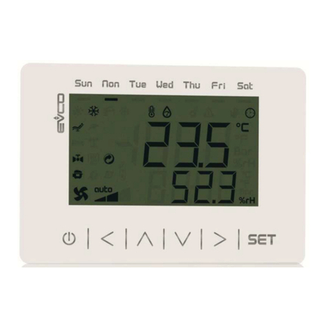
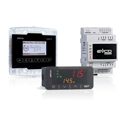
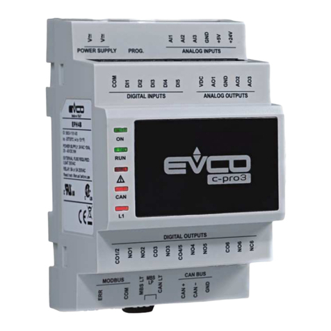
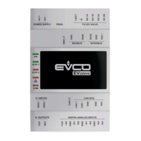
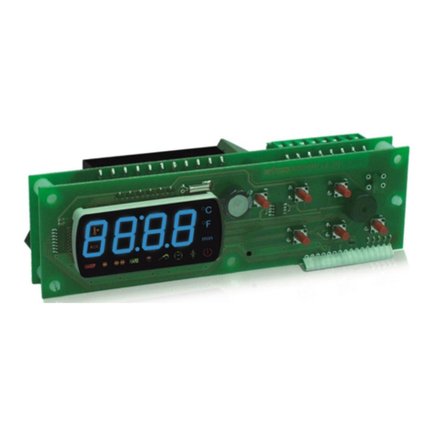
Evco c-pro 3 OEM HRV User guide

c-pro 3 OEM HRV
Controller for advanced controlled mechanical
ventilation units
Application handbook ver. 4.0 August 0 0 | ENGLISH
Code 144CP3OHE404
TheInnovationEvolution

EVCO S.p. . c-pro 3 OEM HRV | pplication handbook ver. 4.0 | Code 144CP3OHE404
page 2 of 138
IMPORT NT
Read this document thoroughly before installation and before use of
the device and follow all recommendations; keep this document
with the device for future consultation.
Use the device only in the ways described in this document.

EVCO S.p. . c-pro 3 OEM HRV | pplication handbook ver. 4.0 | Code 144CP3OHE404
page 3 of 138
Index
1
INTRODUCTION ....................................................................................................................................................................................................... 6
1.1
Preliminary notes ................................................................................................................................................................................... 6
1.2
Models available, technical features and purchase codes ............................................................................................................................. 7
2
DESCRIPTION ......................................................................................................................................................................................................... 13
2.1
Description of c-pro 3 OEM HRV .............................................................................................................................................................. 13
2.2
Description of EVJ LCD and EPJ LCD ........................................................................................................................................................ 14
2.3
Description of EPJgraph ......................................................................................................................................................................... 15
2.4
Description of EPcolor S ......................................................................................................................................................................... 16
2.5
Description of EVD EXP .......................................................................................................................................................................... 17
3
DIMENSIONS ND INST LL TION ............................................................................................................................................................................. 18
3.1
c-pro 3 OEM HRV dimensions and installation ........................................................................................................................................... 18
3.2
Description and installation of EVJ LCD and EPJ LCD .................................................................................................................................. 19
3.3
Dimensions and installation of EPJgraph .................................................................................................................................................. 20
3.4
Dimensions and installation of EPcolor S .................................................................................................................................................. 21
3.5
Dimensions and installation of EVD EXP ................................................................................................................................................... 22
4
ELECTRIC CONNECTION ........................................................................................................................................................................................... 23
4.1
c-pro 3 OEM HRV connectors .................................................................................................................................................................. 23
4.2
EVJ LCD connectors .............................................................................................................................................................................. 25
4.3
EPJ LCD connectors ............................................................................................................................................................................... 26
4.4
EPJgraph connectors ............................................................................................................................................................................. 27
4.5
EPcolor S connectors ............................................................................................................................................................................. 28
4.6
EVD EXP connectors .............................................................................................................................................................................. 30
4.7
Termination of RS-485 MODBUS and C N networks .................................................................................................................................. 31
4.8
Example of electrical connection of a c-pro 3 OEM HRV controller ............................................................................................................... 33
4.9
Example of electrical connection of an EVJ LCD user interface .................................................................................................................... 33
4.10
Example of electrical connection of an EPJ LCD user interface ..................................................................................................................... 35
4.11
Example of electrical connection of an EPJgraph ....................................................................................................................................... 36
4.12
Example of electrical connection of an EPcolor S ....................................................................................................................................... 38
4.13
Example of electrical connection of an EVD EXP I/O expansion ................................................................................................................... 40
5
USER INTERF CE .................................................................................................................................................................................................... 41
5.1
EPJgraph keypad and display ................................................................................................................................................................. 41
5.2
List of pages ........................................................................................................................................................................................ 42
5.3
Passwords ............................................................................................................................................................................................ 43
5.4
Main page ............................................................................................................................................................................................ 43
5.5
Meaning of display icons on c-pro 3 OEM HRV and on EVJLCD and EPJ LCD interfaces ................................................................................... 44
5.6
EPJgraph and EPcolor user interface ........................................................................................................................................................ 45
5.7
c-pro 3 OEM HRV display and EVJ LCD and EPJ LCD user interfaces............................................................................................................. 46
5.8
General menu ...................................................................................................................................................................................... 55
5.9
User menu ........................................................................................................................................................................................... 55
5.10
Servicer menu ...................................................................................................................................................................................... 55
5.11
Installer menu ...................................................................................................................................................................................... 56
5.12
Manufacturer menu ............................................................................................................................................................................... 56
5.13
RTC menu ............................................................................................................................................................................................ 57
5.14
larms menu ........................................................................................................................................................................................ 57
5.15
larm history menu............................................................................................................................................................................... 57
5.16
Menu save/restore/parameters imp. exp. ................................................................................................................................................. 57
5.17
Info menu ............................................................................................................................................................................................ 57
6
LIST OF P R METERS .............................................................................................................................................................................................. 58
6.1
List of configuration parameters ............................................................................................................................................................. 58
6.2
I/O Table I ( nalogue Inputs) parameters .............................................................................................................................................. 81
6.3
I/O Table DI (Digital Inputs) parameters ................................................................................................................................................. 83
6.4
I/O Table DO (Digital Outputs) parameters .............................................................................................................................................. 84
6.5
I/O Table O ( nalogue Outputs) parameters........................................................................................................................................... 85
7
djustments ........................................................................................................................................................................................................... 88
7.1
Machine status ..................................................................................................................................................................................... 88
7.2
OFF by alarm status .............................................................................................................................................................................. 88
7.3
Operating mode control ......................................................................................................................................................................... 88
7.4
Set real time clock ................................................................................................................................................................................ 89
7.5
System set-up ...................................................................................................................................................................................... 89
7.6
Initial page set-up ................................................................................................................................................................................ 90
7.7
Fans set-up .......................................................................................................................................................................................... 90
7.8
Coil 1 set-up ........................................................................................................................................................................................ 91
7.9
Coil 2 set-up ........................................................................................................................................................................................ 93
7.10
Electric coil set-up ................................................................................................................................................................................ 93
7.11
Pre-heating coil set-up .......................................................................................................................................................................... 95
EVCO S.p. . c-pro 3 OEM HRV | pplication handbook ver. 4.0 | Code 144CP3OHE404
page 4 of 138
7.12
Re-heating coil set-up ........................................................................................................................................................................... 95
7.13
Heat exchanger set-up .......................................................................................................................................................................... 96
7.14
Setup using machine code ..................................................................................................................................................................... 97
7.15
Fans .................................................................................................................................................................................................... 99
7.16
Digital step regulation (PF01 = 0) ........................................................................................................................................................... 99
7.17
Modulating temperature regulation (PF01 = 1) ....................................................................................................................................... 100
7.18
Constant pressure/flow regulation (PF01 = 2) (PF01 = 3) ........................................................................................................................ 101
7.19
Q step regulation (PF01 = 4) .............................................................................................................................................................. 102
7.20
Q modulating regulation (PF01 = 5) .................................................................................................................................................... 102
7.21
Time band regulation (PF01 = 6) .......................................................................................................................................................... 103
7.22
Manual regulation (PF01 = 7) ............................................................................................................................................................... 103
7.23
Set-speed forced by keypad or DI ......................................................................................................................................................... 103
7.24
Fan booster function (for units without warm-up damper only) ................................................................................................................. 103
7.25
Minimum/maximum supply temperature ................................................................................................................................................ 104
7.26
Extraction cycles ................................................................................................................................................................................. 104
7.27
Fan status .......................................................................................................................................................................................... 104
7.28
Fan alarm inputs ................................................................................................................................................................................. 104
7.29
mbient temperature probe error ......................................................................................................................................................... 105
8
Main controls ........................................................................................................................................................................................................ 105
8.1
Cooling and heating regulation ............................................................................................................................................................. 105
8.2
Modulating coil adjustment .................................................................................................................................................................. 106
8.3
Coil on-off adjustment ......................................................................................................................................................................... 107
8.4
3-point control of water coils ................................................................................................................................................................ 108
8.5
Second coil ........................................................................................................................................................................................ 108
8.6
Pre-heating coil .................................................................................................................................................................................. 109
8.7
Re-heating coil ................................................................................................................................................................................... 109
8.8
Water coil temperature check ............................................................................................................................................................... 110
8.8.1
Input for heat pump operation mode .................................................................................................................................... 110
8.9
Pre-heating function ............................................................................................................................................................................ 110
8.10
Electric coils ....................................................................................................................................................................................... 111
8.10.1
Coil with ON-OFF heating elements (digital) .......................................................................................................................... 111
8.10.2
Coil with modulating heating element ................................................................................................................................... 111
8.10.3
Coil with modulating heating element + 1 on/off step ............................................................................................................. 111
8.10.4
Coil with modulating heating element + N on/off steps ........................................................................................................... 112
8.10.5
Heating element status ....................................................................................................................................................... 112
8.11
Single coil unit .................................................................................................................................................................................... 112
8.12
Direct expansion coil ........................................................................................................................................................................... 112
8.12.1
1-step direct expansion coil ................................................................................................................................................. 113
8.12.2
2-step direct expansion coil ................................................................................................................................................. 113
8.12.3
Modulating direct expansion coil ........................................................................................................................................... 114
8.12.4
Compressor switch-on sequence .......................................................................................................................................... 115
8.12.5
Compressor defrosting ........................................................................................................................................................ 115
8.12.6
Compressor status ............................................................................................................................................................. 116
8.13
Pumps ............................................................................................................................................................................................... 116
8.13.1
Continuous operation .......................................................................................................................................................... 116
8.13.2
Operation on adjustment request ......................................................................................................................................... 116
8.13.3
Pump status ...................................................................................................................................................................... 117
8.13.4
Pump alarm inputs ............................................................................................................................................................. 117
8.14
Dehumidification ................................................................................................................................................................................. 117
8.14.1
Dehumidification control ..................................................................................................................................................... 117
8.14.2
Limit control on dehumidification .......................................................................................................................................... 117
8.14.3
Winter dehumidification ...................................................................................................................................................... 118
8.15
Humidification .................................................................................................................................................................................... 118
8.15.1
Humidifier enabling (depending on the supply temperature) .................................................................................................... 118
8.15.2
Humidifier On/Off ............................................................................................................................................................... 119
8.15.3
Modulating humidifier with enabling step ............................................................................................................................... 119
8.15.4
Maximum humidification adjustment (in supply) .................................................................................................................... 120
8.15.5
Humidifier status ................................................................................................................................................................ 120
8.16
Mixing chamber damper ...................................................................................................................................................................... 120
8.16.1
Modulating damper control .................................................................................................................................................. 120
8.16.2
Fixed opening regulation ..................................................................................................................................................... 120
8.16.3
Enabling Free-Cooling and Free-Heating in temperature .......................................................................................................... 121
8.16.4
Free-Cooling and Free-Heating adjustment ............................................................................................................................ 121
8.16.5
ir quality control ............................................................................................................................................................... 122
8.16.6
Out-of-range adjustment .................................................................................................................................................... 122
8.16.7
Damper status ................................................................................................................................................................... 122

EVCO S.p. . c-pro 3 OEM HRV | pplication handbook ver. 4.0 | Code 144CP3OHE404
page 5 of 138
8.17
Warm-up damper ............................................................................................................................................................................... 122
8.18
Recovery heat exchangers ................................................................................................................................................................... 123
8.18.1
Cross-flow heat exchanger .................................................................................................................................................. 123
8.18.2
Double coil recovery heat exchanger .................................................................................................................................... 125
8.18.3
Rotating heat exchanger ..................................................................................................................................................... 125
8.18.4
Heat exchanger efficiency calculator ..................................................................................................................................... 126
8.18.5
Heat exchanger status ........................................................................................................................................................ 126
8.19Regolazioni ausiliarie .................................................................................................................................................................................................. 126
9
M N GEMENT OF OTHERS ..................................................................................................................................................................................... 128
9.1
Compensation for setpoint ................................................................................................................................................................... 128
9.2
Last date of maintenance ..................................................................................................................................................................... 128
9.3
utomatic daylight saving time ............................................................................................................................................................. 128
10
DI GNOSTICS ...................................................................................................................................................................................................... 129
10.1
Manual and automatic alarms ............................................................................................................................................................... 129
10.2
Manual alarms .................................................................................................................................................................................... 129
10.3
utomatic-reset alarms ....................................................................................................................................................................... 129
10.4
larms Table ...................................................................................................................................................................................... 129
10.5
ir flow switch alarm ........................................................................................................................................................................... 131
10.6
High pressure alarm ............................................................................................................................................................................ 132
10.7
Low pressure alarm ............................................................................................................................................................................. 132
10.8
Fire/smoke alarm ................................................................................................................................................................................ 132
10.9
Timed air filter pressure switch alarm .................................................................................................................................................... 132
10.10
larm relay ........................................................................................................................................................................................ 132
11
CCESSORIES ...................................................................................................................................................................................................... 133
11.1
ccessories for c-pro 3 OEM HRV .......................................................................................................................................................... 133
12
TECHNIC L SPECIFIC TIONS.................................................................................................................................................................................. 135

EVCO S.p. . c-pro 3 OEM HRV | pplication handbook ver. 3.0 | Code 144CP3OHE304
1INTRODUCTION
1.1 Preliminary notes
The c-pro 3 OEM HRV programmable controller has been designed for the advanced management of mechanical ventilation units to renew and treat air in household
settings. It complies with the increasingly stringent regulations governing air quality and energy certification in buildings.
The independent management of the input and extraction fan (both EC and varied speed types) allows for the best flow in any situation.
Room comfort is achieved by the management capabilities of different types of heat exchangers (with free cooling and heating) and heating/cooling sources.
The BLE module integrated in the EVJ LCD interface provides the end user with easy, intuitive control of the unit, thanks to EVcontrol PP for iOs and ndroid platforms
which transforms your smartphone or tablet into a sophisticated remote control.

EVCO S.p. . c-pro 3 OEM HRV | pplication handbook ver. 4.0 | Code 144CP3OHE404
page 7 of 138
1. Models available, technical features and purchase codes
The following table outlines the models available, purchase codes and technical features of c-pro 3 OEM HRV controllers.
Format
8 open DIN modules • •
8 closed DIN modules • •
User interface
Blind version • • •
LED display on two lines + 6 keys •
Installation
On DIN rail • • • •
Connections
Fixed screw terminal blocks •
Plug-in screw terminal blocks • • •
Power supply
115... 230 V C • • • •
Analogue-digital inputs
Configurable 7 7 7 7
Digital inputs
Configurable 4 4 4 4
Analogue outputs
Configurable 4 4 4 4
Digital outputs
Configurable 6 6 6 6
Communications ports
INTR BUS • • • •
RS-485 master/slave • • • •
C N • • • •
USB • • • •
Other features
Clock • • • •
Purchase codes
Purchase code EPB9ORX1 H EPB9ORE1 H EPB9BRE1 H EPB9LRE1 H

EVCO S.p. . c-pro 3 OEM HRV | pplication handbook ver. 4.0 | Code 144CP3OHE404
page 8 of 138
The following table outlines the models available, the purchase codes and the technical features of the EVJ LCD user interfaces.
Format
111.4 x 76.4 mm • • • • • • • •
User interface
LCD display + 6 capacitive keys • • • • • • • •
Installation
Wall-mounted • • • •
Wall-mounted with rear slot for flush-fit box
• • • •
Connections
Fixed screw terminal blocks • • • • • • • •
Power supply
12 V C/DC • • • •
115... 230 V C • • • •
Analogue inputs
nalogue inputs 2 2 2 2
Communications ports
INTR BUS • • • • • • • •
Other features
larm buzzer • • • • • • • •
Built-in temperature and humidity sensor • • • •
Built-in Bluetooth Low Energy sensor • • • •
Purchase codes
Purchase code
EVJD900N2VW
EVJD900N2VWIV
EVJD920N2VW
EVJD920N2VWIV
EVJD902N9VP
EVJD902N9VPIV
EVJD922N9VP
EVJD922N9VPIV
(1)
With INTR BUS communications protocol
The EVJ LCD user interfaces are also available in the version for panel installation; for further information, please contact the EVCO sales network.

EVCO S.p. . c-pro 3 OEM HRV | pplication handbook ver. 4.0 | Code 144CP3OHE404
page 9 of 138
The following table outlines the models available, the purchase codes and the technical features of the EPJ LCD user interfaces.
Format
111.4 x 76.4 mm • • • •
User interface
LCD display + 6 capacitive keys • • • •
Installation
Wall-mounted • •
Wall-mounted with rear slot for flush-fit box
• •
Connections
Fixed screw terminal blocks • • • •
Power supply
12 V C/DC • •
115... 230 V C • •
Analogue inputs
nalogue inputs 2 2
Communications ports
C N • • • •
USB • • • •
Other features
larm buzzer • • • •
Built-in temperature and humidity sensor • •
Purchase codes
Purchase code EPJD900N3VW EPJD920N3VW EPJD902N9VP EPJD922N9VP

EVCO S.p. . c-pro 3 OEM HRV | pplication handbook ver. 4.0 | Code 144CP3OHE404
page 10 of 138
La seguente tabella illustra i modelli disponibili, i codici di acquisto e le caratteristiche tecniche delle interfacce utente EPJgraph.
Format
111.4 x 76.4 mm • •
User interface
2.8 in colour LCD graphic display + 6 capacitive keys • •
Installation
Panel mounting •
Wall mounting •
Connections
Fixed screw terminal blocks •
Plug-in screw terminal blocks •
Power supply
24 V C/12... 30 VDC • •
Communications ports
C N • •
Other features
larm buzzer • •
Purchase codes
Purchase code EPJG900X4 EPJG900X4VW

EVCO S.p. . c-pro 3 OEM HRV | pplication handbook ver. 4.0 | Code 144CP3OHE404
page 11 of 138
The following table outlines the models available, the purchase codes and the technical features of the EPcolor S user interfaces.
Format
111.4 x 76.4 mm • •
User interface
3.5 in TFT touch-screen graphic display • •
Installation
Panel mounting •
Wall mounting •
Connections
Fixed screw terminal blocks •
Plug-in screw terminal blocks •
Power supply
24 V C/12... 30 VDC • •
Communications ports
MODBUS master/slave RS-485 • •
C N • •
USB • •
Other features
Real time clock • •
larm buzzer • •
Purchase codes
Purchase code EPCJ01X4EXX H da codificare

EVCO S.p. . c-pro 3 OEM HRV | pplication handbook ver. 4.0 | Code 144CP3OHE404
page 12 of 138
The following table outlines the models available, the purchase codes and the technical features of the EVD EXP user interfaces.
Format
4 closed DIN modules •
User interface
Blind version •
Installation
On DIN rail •
Connections
Plug-in screw terminal blocks •
Power supply
115... 230 V C •
Analogue inputs
Configurable 4
Digital inputs
Configurable 6
Analogue outputs
Configurable 2
Digital outputs
Configurable 4
Communications ports
INTR BUS •
Purchase codes
Purchase code EVD094EM9

EVCO S.p. . c-pro 3 OEM HRV | pplication handbook ver. 4.0 | Code 144CP3OHE404
page 13 of 138
DESCRIPTION
.1 Description of c-pro 3 OEM HRV
The following diagram shows the appearance of the c-pro 3 OEM HRV controllers.
The following table illustrates the meaning of the parts of the c-pro 3 OEM HRV controllers.
P RT ME NING
1 plug-in screw terminal blocks, male only, for digital outputs (fixed screw terminal blocks in model EPB9ORX1 H)
2 plug-in screw terminal blocks, male only, for high-voltage digital inputs (fixed screw terminal blocks in model EPB9ORX1 H)
3 plug-in screw terminal block, male only, for power supply (fixed screw terminal blocks in model EPB9ORX1 H)
4 user interface (only available in model EPB9LRE1 H)
5
micro-switch for:
- termination of RS-485 MODBUS network
- termination of C N network
6 plug-in screw terminal blocks, male only, for C N port, RS-485 port and INTR BUS port (fixed screw terminal blocks in model EPB9ORX1 H)
7 USB type connector for parameter configuration (fixed screw terminal blocks in model EPB9ORX1 H)
8 plug-in screw terminal blocks, male only, for analogue inputs, dry contact digital inputs for and analogue outputs (fixed screw terminal blocks in model
EPB9ORX1 H)
9 Signalling LED
For further information, see the following sections.

EVCO S.p. . c-pro 3 OEM HRV | pplication handbook ver. 4.0 | Code 144CP3OHE404
page 14 of 138
. Description of EVJ LCD and EPJ LCD
The following diagram shows the appearance of user interfaces EVJ LCD and EPJ LCD.
The following table illustrates the meaning of the parts of the user interfaces EVJ LCD and EPJ LCD.
P RT ME NING
1 display
2 On/Off key (subsequently also called the “On/stand-by key”)
3 left key (subsequently also called “left key”)
4 increase key (subsequently also called the “up key”)
5 decrease key (subsequently also called “down key”)
6 right key (subsequently also called the “right key”)
7 settings key (subsequently also called “set”)
8 Fixed screw terminal block for power supply and for INTR BUS port (in models EVJ LCD) or C N port (in models EPJ LCD)
9 - in models EPJ LCD, micro switch for the termination of the C N network
- not otherwise present
10 - reserved in models EVJ LCD
- in models EPJ LCD, Micro USB connector for device programming
11 fixed screw terminal block for analogue inputs
12 fixed screw terminal block for power supply
For further information, see the following sections.

EVCO S.p. . c-pro 3 OEM HRV | pplication handbook ver. 4.0 | Code 144CP3OHE404
page 15 of 138
.3 Description of EPJgraph
The following diagram shows the appearance of the EPJgraph user interfaces.
The following diagram illustrates the meaning of the parts of the EPJgraph user interfaces.
P RT ME NING
1 display
2 on/off key (subsequently also called the “On/stand-by key”)
3 left key (subsequently also called “left key”)
4 increase key (subsequently also called the “up key”)
5 decrease key (subsequently also called “down key”)
6 right key (subsequently also called the “right key”)
7 settings key (subsequently also called “set”)
8 on/off LED
9 alarm LED
10 power supply LED
11 plug-in or fixed screw terminal block for power supply and C N port
12 micro switch for the termination of the C N network
13 reserved EVCO
For further information, see the following sections.

EVCO S.p. . c-pro 3 OEM HRV | pplication handbook ver. 4.0 | Code 144CP3OHE404
page 16 of 138
.4 Description of EPcolor S
The following diagram shows the appearance of the EPcolor S user interfaces.
The following diagram illustrates the meaning of the parts of the EPJgraph user interfaces.
P RT ME NING
1 display
2 plug-in screw terminal block for MODBUS master/slave RS-485 port
3 plug-in screw terminal block for power supply and C N port
4 micro switch for the termination of the MODBUS RS-485 and C N network
5 USB port for programming the device
6 fixed screw terminal block for power supply, MODBUS master/slave RS-485 and C N port
For further information, see the following sections.

EVCO S.p. . c-pro 3 OEM HRV | pplication handbook ver. 4.0 | Code 144CP3OHE404
page 17 of 138
.5 Description of EVD EXP
The following diagram shows the appearance of the EVD EXP I/O expansions.
The following table illustrates the meaning of the parts of the EVD EXP I/O expansions.
P RT ME NING
1 Male Micro-Fit connector for analogue inputs, digital inputs, analogue outputs and open collector digital output
2 Plug-in screw terminal block, male only, for INTR BUS port
3 plug-in screw terminal block, male only, for digital outputs
4 plug-in screw terminal block, male only, for power supply and digital outputs
For further information, see the following sections.

EVCO S.p. . c-pro 3 OEM HRV | pplication handbook ver. 4.0 | Code 144CP3OHE404
page 18 of 138
3DIMENSIONS AND INSTALLATION
3.1 c-pro 3 OEM HRV dimensions and installation
The following diagram outlines the dimensions of the c-pro 3 OEM HRV controllers (8 DIN modules). The dimensions are expressed in mm (in).
It is designed to be installed on a DIN rail in a control panel.
To install the c-pro 3 OEM HRV controllers, follow the indications outlined in the following diagram.
To remove c-pro 3 OEM HRV controllers, first use a screwdriver to remove any plug-in screw terminal blocks inserted in the lower part, then open the clip on the DIN
rail with a screwdriver as illustrated in the following diagram.
To reinstall the c-pro 3 OEM HRV controllers, first press the DIN rail fully in.

EVCO S.p. . c-pro 3 OEM HRV | pplication handbook ver. 4.0 | Code 144CP3OHE404
page 19 of 138
3. Description and installation of EVJ LCD and EPJ LCD
The following diagram shows the dimensions of the EVJ LCD and EPJ LCD user interfaces for wall installation. The dimensions are expressed in mm (in).
They are designed to be mounted on the wall (with rawl plugs and fastening screws) or in a flush-mount box (with fastening screws).
The following diagram shows the dimensions of the EVJ LCD and EPJ LCD user interfaces for wall installation, with a rear slot for a flush-mount box. The dimensions are
expressed in mm (in).
They are designed to be mounted on the wall (with rawl plugs and fastening screws) or in a flush-mount box (with fastening screws).

EVCO S.p. . c-pro 3 OEM HRV | pplication handbook ver. 4.0 | Code 144CP3OHE404
page 20 of 138
3.3 Dimensions and installation of EPJgraph
The following diagram illustrates the EPJgraph user interface dimensions for panel installation. The dimensions are expressed in mm (in).
They are designed to be fitted to a panel, with elastic holding flaps.
The following diagram illustrates the EPJgraph user interface dimensions for wall installation. The dimensions are expressed in mm (in).
They are designed to be mounted on the wall (with rawl plugs and fastening screws) or in a flush-mount box (with fastening screws).
Table of contents
Other Evco Controllers manuals

Evco
Evco EVD HP User guide

Evco
Evco EV3 WEB User manual

Evco
Evco Vcolor 818 User guide

Evco
Evco Vcolor 338 L User guide

Evco
Evco EVF214 User manual

Evco
Evco EVX225 User manual

Evco
Evco EV3B24 User manual

Evco
Evco C-pro 3 giga User manual

Evco
Evco EVJ 700 Instructions for use

Evco
Evco c-pro 3 nano CHILL User manual