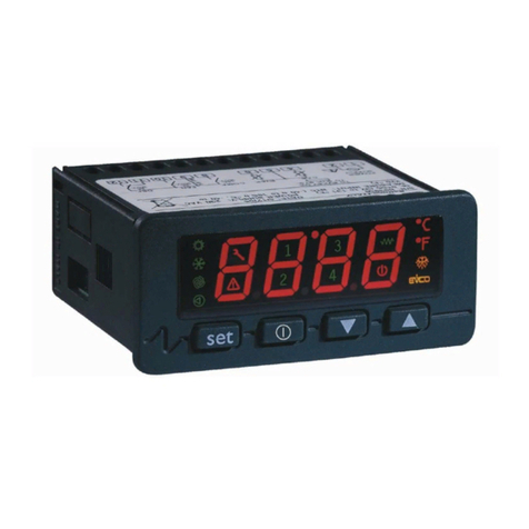
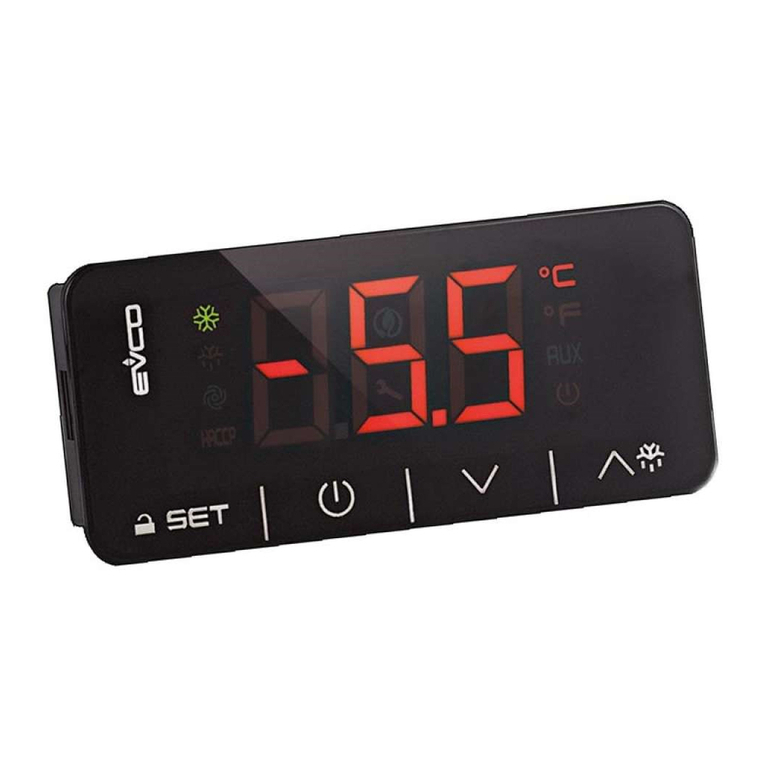
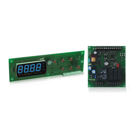
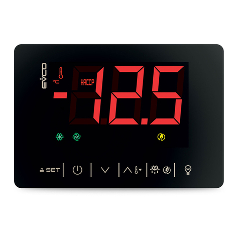
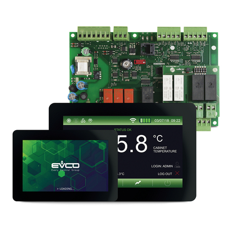
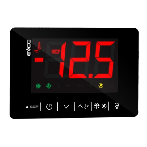
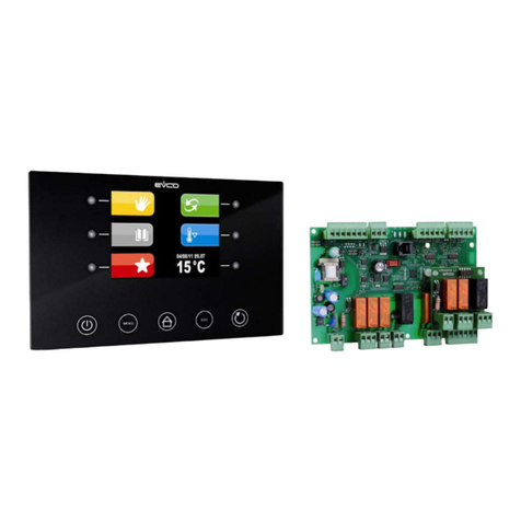
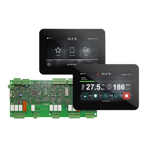
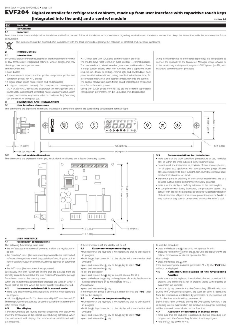
Evco Vcolor 819 User guide

EVCO S.p.A. Vcolor 819 | Installer manual ver. 1.0 | Code 144VC819I104
page
1 of 84
Vcolor 819
Controllers for top-class blast chillers, in split
version that can be built into the unit, with 5- or 7-
inch colour TFT touch-screen graphic display in
either vertical or horizontal format
E GLISH
I STALLER MA UAL ver. 1.0
CODE 144VC819I104

EVCO S.p.A. Vcolor 819 | Installer manual ver. 1.0 | Code 144VC819I104
page
2 of 84
Important
ead this document carefully before installation and before using the device and take all the prescribed precautions.
Keep this document with the device for future consultation.
The following symbols are used in this document:
indicates a suggestion
indicates a warning.
The device must be disposed of according to local regulations governing the collection of electrical and electronic
waste.

EVCO S.p.A. Vcolor 819 | Installer manual ver. 1.0 | Code 144VC819I104
page
3 of 84
Index
1
INT ODUCTION ................................................................................................................................... 6
1.1
Introduction ........................................................................................................................................ 6
1.2
Main features of the models available and their purchasing codes .............................................................. 7
2
DESC IPTION .................................................................................................................................... 10
2.1
User interface description .................................................................................................................... 10
2.2
Control module description .................................................................................................................. 12
3
MEASU EMENTS AND INSTALLATION ................................................................................................... 13
3.1
Vcolor 819M user interface measurements ............................................................................................ 13
3.2
Vcolor 819L user interface measurements ............................................................................................. 13
3.3
Control module measurements ............................................................................................................ 14
3.4
Multi-functional module measurements ................................................................................................. 14
3.5
User interface installation .................................................................................................................... 15
3.6
Control and multi-functional module installation ..................................................................................... 15
3.7
Installation precautions ....................................................................................................................... 15
4
ELECT ICAL CONNECTION .................................................................................................................. 16
4.1
Electrical connection of Vcolor 819M ..................................................................................................... 16
4.2
Electrical connection of Vcolor 819L ...................................................................................................... 17
4.3
Precautions for electrical connection ..................................................................................................... 17
5
USE INTE FACE ............................................................................................................................... 18
5.1
Initial information .............................................................................................................................. 18
5.2
Initial switch-on ................................................................................................................................. 18
5.3
Switching the device on and off ........................................................................................................... 19
5.4
Lock/unlock keypad ............................................................................................................................ 20
5.5
Silencing the buzzer ........................................................................................................................... 20
5.6
Door-open signal................................................................................................................................ 20
6
FUNCTION MODES ............................................................................................................................. 21
6.1
Initial information on operating cycles .................................................................................................. 21
6.2
Initial information on the needle probe ................................................................................................. 21
6.3
Selecting the operating mode .............................................................................................................. 22
7
BLAST-CHILLING MODE ...................................................................................................................... 23
7.1
Blast chilling/blast-freezing and conservation ........................................................................................ 24
7.2
Hard blast chilling/soft blast-freezing and conservation ................................................................................ 26
7.3
Continuous cycle ................................................................................................................................ 26
7.3.1
Multineedle probe mode .............................................................................................................. 27
7.3.2
Multi-timer mode ........................................................................................................................ 27
7.4
Customized cycle ............................................................................................................................... 28
7.5
Setting the set points ......................................................................................................................... 29
7.5.1
Setting the cabinet temperature set point ...................................................................................... 29
7.5.2
Setting the product temperature set point ..................................................................................... 29
7.5.3
Setting the cycle duration ............................................................................................................ 29
7.5.4
Setting the fan speed .................................................................................................................. 30
7.6
unning the cycle............................................................................................................................... 30
7.6.1
Needle probe insertion test .......................................................................................................... 31
7.6.2
ecording historical data ............................................................................................................. 31
7.6.3
Cycle end .................................................................................................................................. 32
8
SPECIAL CYCLES MODE ...................................................................................................................... 34

EVCO S.p.A. Vcolor 819 | Installer manual ver. 1.0 | Code 144VC819I104
page
4 of 84
8.1
Fish sanitation ................................................................................................................................... 35
8.2
Thawing ............................................................................................................................................ 37
8.3
Defrosting ......................................................................................................................................... 39
8.4
Ice cream hardening........................................................................................................................... 40
8.5
Cabinet sterilisation ............................................................................................................................ 41
8.6
Heating the needle probe .................................................................................................................... 41
8.7
Drying .............................................................................................................................................. 42
8.8
Proofing ............................................................................................................................................ 43
8.8.1
Description of proofing ................................................................................................................ 43
8.8.2
Setting up a proofing cycle .......................................................................................................... 43
8.9
Slow cooking ..................................................................................................................................... 45
9
ECIPE BOOK MODE ........................................................................................................................... 46
9.1
Pre-set blast chilling recipes ................................................................................................................ 48
9.2
Pre-set blast-freezing recipes .............................................................................................................. 49
9.3
Saving a recipe .................................................................................................................................. 49
9.4
Over-writing a recipe .......................................................................................................................... 50
10
P E-COOLING MODE .......................................................................................................................... 51
11
ADJUSTMENTS ................................................................................................................................... 52
11.1
Door frame heating output .............................................................................................................. 52
11.2
Compressor management................................................................................................................ 52
11.3
Pump down solenoid valve management ........................................................................................... 53
11.4
Evaporator fan management............................................................................................................ 53
11.5
Condenser fan management ............................................................................................................ 54
11.6
Alarm output management .............................................................................................................. 54
11.7
Needle probe heating management .................................................................................................. 54
11.8
Cabinet sterilisation management..................................................................................................... 55
11.9
Defrost output management ............................................................................................................ 55
11.10
Thawing heater management........................................................................................................... 55
11.11
Proofing and slow cooking heater management .................................................................................. 55
11.12
Humidifier management .................................................................................................................. 55
11.13
Humidifying/steam generator heater management ............................................................................. 55
11.14
Cabinet light management............................................................................................................... 55
12
SETTINGS ......................................................................................................................................... 56
12.1
Service ......................................................................................................................................... 56
12.2
Setup ........................................................................................................................................... 56
12.3
Select language ............................................................................................................................. 56
12.4
Configure Wi-Fi .............................................................................................................................. 57
12.4.1
Initial information ....................................................................................................................... 57
12.4.2
Access to the network ................................................................................................................. 57
12.4.3
Connection to Cloud Evolution ...................................................................................................... 58
12.4.4
Connection diagnostics ................................................................................................................ 58
13
USING THE USB PO T ........................................................................................................................ 59
13.1
Initial information ........................................................................................................................... 59
13.2
Download/upload recipes ................................................................................................................ 59
13.3
Download/upload parameters .......................................................................................................... 60
13.4
Download HACCP data .................................................................................................................... 60
14
LIST OF CONFIGU ATION PA AMETE S ............................................................................................... 61
15
ALA MS ............................................................................................................................................ 72

EVCO S.p.A. Vcolor 819 | Installer manual ver. 1.0 | Code 144VC819I104
page
5 of 84
15.1
Alarms .......................................................................................................................................... 72
15.2
HACCP alarms ................................................................................................................................ 77
16
ACCESSO IES ................................................................................................................................... 78
16.1
EVC20P52N9XXX10 - Multi-functional module .................................................................................... 78
16.2
ECTSFD004 - 230 VAC/12 VAC 20 VA safety transformer .................................................................... 78
16.3
EVIF20SUXI - Non-optoisolated S-485/USB serial interface ............................................................... 78
16.4
0812000002 - USB plug for panel installation .................................................................................... 78
16.5
0810500018/0810500020 - Connecting cables .................................................................................. 79
16.6
EVDFAN1 - Phase cutting speed regulator for single-phase fans ........................................................... 79
16.7
EVUSB4096M - 4GB USB flash drive ................................................................................................. 79
17
TECHNICAL SPECIFICATIONS .............................................................................................................. 80
17.1
Technical specifications ................................................................................................................... 80

EVCO S.p.A. Vcolor 819 | Installer manual ver. 1.0 | Code 144VC819I104
page
6 of 84
1I TRODUCTIO
1.1 Introduction
The Vcolor 819 series is a range of stylish controllers
for managing top-class blast chillers.
Available in split version, the user interface can be
built into the unit mechanically for optimum aesthetic
effect. It consists of a 5-inch (Vcolor 819M) or 7-inch
(Vcolor 819L) capacitive TFT touch-screen graphic
display, in either vertical or horizontal format. The
display features 65K colours, 800 x 480 pixel
resolution and guarantees IP65 protection, for easy
cleaning.
These controllers can run positive and negative blast
chilling cycles, both temperature and time controlled,
with hard/soft and blast chilling intensity management
functions, the latter requiring an external fan speed
regulator. Before each temperature cycle, a test is run
to check that the needle probe is correctly inserted
(including multipoint probes).
An external multi-functional module makes it possible
to transform the blast chiller into a multi-functional
device for managing retarding-proofing and slow
cooking cycles. It is also possible to team a slow
cooking function with subsequent holding or blast
chilling and conservation functions.
The user interface is installed from behind using
threaded studs, making the display flush with the
front.

EVCO S.p.A. Vcolor 819 | Installer manual ver. 1.0 | Code 144VC819I104
page
7 of 84
1.2 Main features of the models available and their
purchasing codes
The table below shows the main features of the models available and the purchasing codes.
MAIN FEATU ES
AVAILABLE MODELS AND KIT
PU CHASING CODES OPTIONS
Vcolor 819M (5") Vcolor 819L (7") multi-functional
module
Vertical display EVCMC819P9E EVCLC819P9E
EVC20P52N9XXX10
Horizontal display EVCMC829P9E EVCLC829P9E
Power supply
control module 115... 230 VAC 115... 230 VAC
user interface with separate power supply 12 VAC
user interface powered by control module •
additional module 115...230 VAC
Analogue inputs
cabinet probe PTC/NTC PTC/NTC
needle probe (sensor 1) PTC/NTC PTC/NTC
needle probe (sensor 2) PTC/NTC PTC/NTC
needle probe (sensor 3) PTC/NTC PTC/NTC
evaporator probe PTC/NTC PTC/NTC
condenser probe PTC/NTC PTC/NTC
Digital inputs
door switch • •
compressor thermal switch • •
low pressure switch • •
high pressure switch • •
Analogue outputs
PWM, for speed regulators (evaporator fan) • •

EVCO S.p.A. Vcolor 819 | Installer manual ver. 1.0 | Code 144VC819I104
page
8 of 84
MAIN FEATU ES
AVAILABLE MODELS AND KIT
PU CHASING CODES OPTIONS
Vcolor 819M (5") Vcolor 819L (7") multi-functional
module
Vertical display EVCMC819P9E EVCLC819P9E
EVC20P52N9XXX10
Horizontal display EVCMC829P9E EVCLC829P9E
Digital outputs
electro-mechanical relays; A res. @ 250 VAC
compressor 30 A 30 A
defrost 8 A 8 A
evaporator fan 8 A 8 A
condenser fan 8 A 8 A
door heater 8 A 8 A
thawing heater 16 A 16 A
alarm (configurable) (1) 16 A 16 A
pump down valve (configurable) (2) 8 A 8 A
needle probe heater (configurable) (3) 8 A 8 A
cabinet heater 30 A
steam generator 16 A
steam injection 8 A
Communications ports
S-485 MODBUS • •
USB • •
Other features
clock • •
alarm buzzer • •
management of positive and negative blast chilling
cycles, both temperature and time controlled • •
management of blast chilling intensity with fan speed
external regulator • •
management of multipoint or multineedle probes • •

EVCO S.p.A. Vcolor 819 | Installer manual ver. 1.0 | Code 144VC819I104
page
9 of 84
MAIN FEATU ES
AVAILABLE MODELS AND KIT
PU CHASING CODES OPTIONS
Vcolor 819M (5") Vcolor 819L (7") multi-functional
module
Vertical display EVCMC819P9E EVCLC819P9E
EVC20P52N9XXX10
Horizontal display EVCMC829P9E EVCLC829P9E
Other features
management of special cycles (fish sanitation, thawing
and ice cream hardening) • •
management of retarding-proofing and slow cooking
special cycles.
• •
recording HACCP data and graphics processing in real
time • •
ready-to-use OEM recipes and storage of user recipes
(1) configurable as alarm or needle probe heater
(2) configurable as pump down valve or alarm
(3) configurable as cabinet light, UV lamp, needle probe heater or alarm.
Optional models
Models with Wi-Fi connectivity. For more information
contact the EVCO sales network.

EVCO S.p.A. Vcolor 819 | Installer manual ver. 1.0 | Code 144VC819I104
page
10 of 84
2DESCRIPTIO
2.1 User interface description
The diagram below shows the front view of the user interface in the vertical format
The diagram below shows the front view of the user interface in the horizontal format.
PA T DESC IPTION
1 display

EVCO S.p.A. Vcolor 819 | Installer manual ver. 1.0 | Code 144VC819I104
page
11 of 84
The diagram below shows the intended use of the user interface connectors.
PA T DESC IPTION
1 USB port
2 S-485 MODBUS port
3 dip switch for the termination resistor for the S-485 MODBUS port
4 power supply for the user interface and connection between the user interface and the control module
5 dip switch for the resistor connecting the user interface and the control module
6 appliance earthing
For more information see subsequent sections.

EVCO S.p.A. Vcolor 819 | Installer manual ver. 1.0 | Code 144VC819I104
page
12 of 84
2.2 Control module description
The diagram below shows the intended use of the control module connectors.
PA T DESC IPTION
1 control module power supply
2 evaporator fan and condenser fan relay
3 defrost relay
4 compressor relay
5 door heater relay
6 door switch, compressor thermal switch, low pressure switch and high pressure switch
7 thawing heater relay
8 auxiliary relay 1 (see parameter u3)
9 auxiliary relays 2 and 3 (see parameters u1 and u2)
10 cabinet, evaporator and condenser probe
11 needle probe up to 3 sensors
12 unused
13 unused
14 output for phase cutting speed regulator for EVDFAN1 single-phase fans
15 user interface – control module connection
For more information see subsequent sections.

EVCO S.p.A. Vcolor 819 | Installer manual ver. 1.0 | Code 144VC819I104
page
13 of 84
3MEASUREME TS A D I STALLATIO
3.1 Vcolor 819M user interface measurements
The picture below shows the measurements of the 5-inch user interface; measurements are expressed in mm
(inches).
3.2 Vcolor 819L user interface measurements
The picture below shows the measurements of the 7-inch user interface; measurements are expressed in mm
(inches).

EVCO S.p.A. Vcolor 819 | Installer manual ver. 1.0 | Code 144VC819I104
page
14 of 84
3.3 Control module measurements
The picture below shows the measurements of the Vcolor 819 control module; measurements are expressed in mm
(inches).
3.4 Multi-functional module measurements
The picture below shows the measurements of the Vcolor 819 multi-functional module; measurements are expressed
in mm (inches).

EVCO S.p.A. Vcolor 819 | Installer manual ver. 1.0 | Code 144VC819I104
page
15 of 84
3.5 User interface installation
Installed from behind using threaded studs to guarantee flush fitting.
3.6 Control and multi-functional module installation
On a flat surface with spacers.
3.7 Installation precautions
- Ensure that the working conditions for the device (operating temperature, humidity, etc.) are within the
set limits. See section 16 TECHNICAL SPECIFICATIONS.
- Do not install the device close to heat sources (heaters, hot air ducts, etc.), equipment with a strong
magnetic field (large diffusers, etc.), in places subject to direct sunlight, rain, damp, excessive dust,
mechanical vibrations or shocks.
- Any metal items close to the control module must be at a sufficient distance so as not to compromise
the safety distance; any cabling must be placed at least 2 cm away.
- In compliance with safety regulations, the device must be installed properly to ensure adequate
protection from contact with electrical parts. All protective parts must be fixed in such a way as to need
the aid of a tool to remove them.

EVCO S.p.A. Vcolor 819 | Installer manual ver. 1.0 | Code 144VC819I104
page
16 of 84
4ELECTRICAL CO ECTIO
4.1 Electrical connection of Vcolor 819M
The picture below shows the electrical connection of the controller with 5-inch display.

EVCO S.p.A. Vcolor 819 | Installer manual ver. 1.0 | Code 144VC819I104
page
17 of 84
4.2 Electrical connection of Vcolor 819L
The picture below shows the electrical connection of the controller with 7-inch display.
4.3 Precautions for electrical connection
- Do not use electric or pneumatic screwdrivers on the terminal blocks of the device.
- If the device has been moved from a cold to a warm place, the humidity may cause condensation to
form inside. Wait about an hour before switching on the power.
- Make sure that the supply voltage, electrical frequency and power of the device correspond to the local
power supply. See section 17 TECHNICAL SPECIFICATIONS.
- Disconnect the device from the power supply before doing any type of maintenance.
- Do not use the device as safety device.
- For repairs and for further information on the device, contact the EVCO sales network.

EVCO S.p.A. Vcolor 819 | Installer manual ver. 1.0 | Code 144VC819I104
page
18 of 84
5USER I TERFACE
5.1 Initial information
The interface has the following operating modes:
- “off” (no power to the device);
- “stand-by” (the device is powered but switched off);
- “on” (the device is powered, switched on and awaiting start-up of an operating cycle);
- “run” (the device is powered, switched on and running an operating cycle).
Terminology: “switch on the device” means moving from “stand-by” to “on” mode and “switch off the device” means
moving from “on” to “stand-by” mode.
If the power supply fails during “stand-by” or “on” mode, when power is restored the device will return to the mode
set before the failure.
If the power supply fails during “run” mode, when power is restored the device will operate as follows:
- if blast chilling or blast-freezing was in progress, the cycle will resume, taking into account the duration
of the power loss;
- if a conservation cycle was running, this will continue using the same settings;
- if a proofing or slow cooking cycle was running, the cycle will continue where it left off.
5.2 Initial switch-on
Connect the power supply to the device: if parameter E9 is set at 1, the device will show the EVCO splash screen for
10 seconds; if the parameter is set at 0, a system loading screen will be shown:
E9=1
E9=0

EVCO S.p.A. Vcolor 819 | Installer manual ver. 1.0 | Code 144VC819I104
page
19 of 84
Once loading is complete, the device will display the mode it was in before being powered down:
- On/Stand-by screen, press the central area to move to the Home screen;
- directly the Home screen.
On/stand-by screen
→
Home screen
If the power supply has been cut off long enough to cause a clock error (RTC code), it will be necessary to
reset the date and time. The date and time can be set from the settings screen, service section (paragraph
12.1).
5.3 Switching the device on and off
To switch the device on, press the central area in the
On/Stand-by screen and the Home screen will open.
To switch the device off, press the red area at the
bottom of the Home screen.

EVCO S.p.A. Vcolor 819 | Installer manual ver. 1.0 | Code 144VC819I104
page
20 of 84
5.4 Lock/unlock keypad
The keypad can be locked by setting parameter E7 to 1, locking the keypad after the period of inactivity set by
parameter E8.
If the keypad is locked, a pop-up will appear when it is touched indicating that it is locked and how to unlock it. It can
be unlocked by dragging a finger to the right.
5.5 Silencing the buzzer
Press any key while the buzzer is sounding.
5.6 Door-open signal
When the door is opened the signal shown below will appear on the display.
Press any area on the display to remove this signal.
This manual suits for next models
3
Table of contents
Other Evco Controllers manuals

Evco
Evco EVX225 User manual

Evco
Evco EVBOX Light JS200 User manual

Evco
Evco EV3B23 User manual

Evco
Evco EVJ 700 User guide

Evco
Evco Vcolor 379 User guide

Evco
Evco Vcolor 318 M User guide

Evco
Evco EV3 200 WEB User manual

Evco
Evco EVJ 200 User manual

Evco
Evco c-pro 3 OEM User manual

Evco
Evco EVJ 200 Series User manual

Evco
Evco EV3B33N7VXRX04 User manual

Evco
Evco Vcolor 318 M User guide

Evco
Evco EV8338 User manual

Evco
Evco c-pro 3 Series User manual

Evco
Evco EVJ 200 User manual

Evco
Evco EV3 HP User guide

Evco
Evco EV3 CHIL User guide

Evco
Evco c-pro 3 micro AHU User manual

Evco
Evco EV3 Basic Split User manual

Evco
Evco c-pro 3 nano CHILL User manual