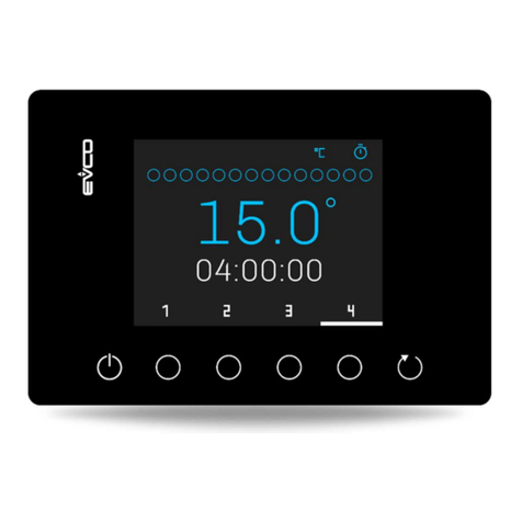
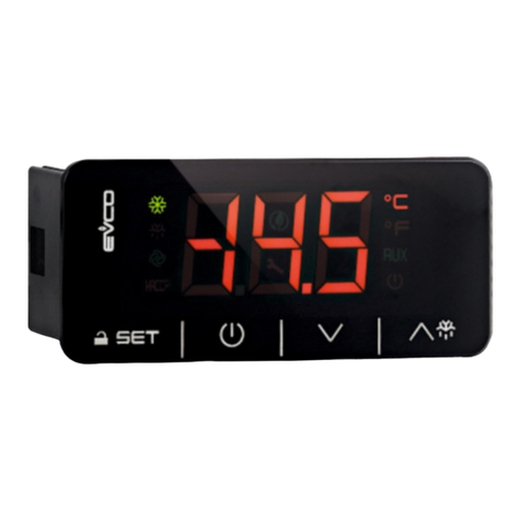
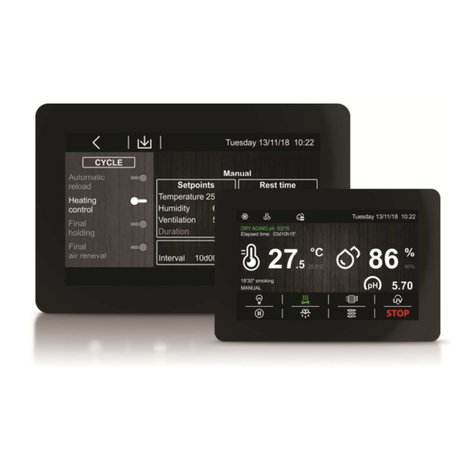
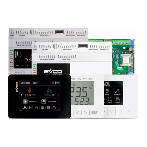
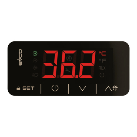
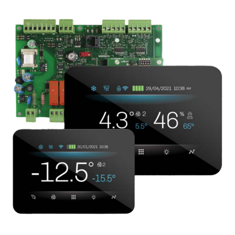
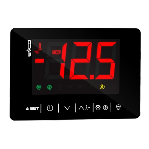
Evco c-pro 3 nano CHIL Instructions for use

EVCO S.p.A.
c-pro 3 nano CHIL | Application manual ver. 1.0 | Code 144C 3NCHE104
c-pro 3 nano CHIL
rogrammable controllers for chillers/heat
pumps with single or dual circuit
Application Manual | ENGLISH
Code 144C 3NCHE104

EVCO S.p.A.
c-pro 3 nano CHIL | Application manual ver. 1.0 | Code 144C 3NCHE104
page 2 of 90
IMPORTANT WARNING
Read the User Manual carefully before installation and before use and follow all the instructions concerning
installation and electrical connections. This manual must be kept for future consultation.
All the devices must e disposed of according to local regulations governing the disposal of
electrical and electronic devices.

EVCO S.p.A.
c-pro 3 nano CHIL | Application manual ver. 1.0 | Code 144C 3NCHE104
page 3 of 90
SUMMARY
1
INTRODUCTION ................................................................................................... 6
1.1
Introduction ..................................................................................................... 6
2
APPLICATIONS .................................................................................................... 7
2.1
Basic scheme of application of an air/water dual-circuit chiller ....................... 8
3
HARDWARE SOLUTIONS ...................................................................................... 9
4
MEASUREMENTS ................................................................................................ 10
4.1
Controller and user interface measurements .................................................. 10
4.1.1
c-pro 3 nano CHIL control module measurements................................................................................. 10
4.1.2
c-pro 3 EXP micro+ control module measurements ............................................................................... 10
4.1.3
Vgraph remote user interface measurements ....................................................................................... 11
4.1.4
EVDRIVE03 module measurements ....................................................................................................... 11
5
USER INTERFACE ............................................................................................... 12
5.1
Viewing and Key oards .................................................................................. 12
5.1.1
C-pro 3 nano+ controller user interface: ............................................................................................... 12
5.1.2
Vgraph/Vcolor user interface: ............................................................................................................... 13
6
LIST OF THE PAGES............................................................................................ 14
6.1
Passwords ...................................................................................................... 14
6.2
Unit OFF Main screen ...................................................................................... 15
6.3
Unit ON Main screen ....................................................................................... 15
6.4
StAt Menu ....................................................................................................... 16
6.4.1
LED Meaning ......................................................................................................................................... 17
6.5
General Menu ................................................................................................. 18
6.6
User Menu ...................................................................................................... 19
6.7
Maintenance Menu .......................................................................................... 19
6.8
Installer Menu ................................................................................................ 19
6.9
Manufacturer Menu ........................................................................................ 20
6.10
RTC Menu .................................................................................................... 20
6.11
Alarm Menu ................................................................................................. 20
7
LIST OF PARAMETERS ........................................................................................ 21
7.1
List of Configuration Parameters .................................................................... 22
7.2
AI Configuration ............................................................................................. 39
7.3
DI Configuration ............................................................................................. 40
7.4
AO Configuration ............................................................................................ 41
7.5
DO Configuration (HD01-HD18 parameters)................................................... 41
8
REGULATIONS.................................................................................................... 43
8.1
Machine State ................................................................................................. 43
8.2
Type of Unit .................................................................................................... 44
8.2.1
Water/water and air/water chillers with EVDRIVE03 ........................................................................... 44
8.2.2
Water/water and air/water chillers (NO EVDRIVE03) .......................................................................... 45
8.2.3
Water/water and air/water heat pump with EVDRIVE03 ...................................................................... 46
8.2.4
Water/water and air/water heat pump no EVDRIVE03 ......................................................................... 47

EVCO S.p.A.
c-pro 3 nano CHIL | Application manual ver. 1.0 | Code 144C 3NCHE104
page 4 of 90
8.3
Configuration of the Circuits ........................................................................... 48
8.4
Operating Mode Control .................................................................................. 49
8.5
Setting the RTC .............................................................................................. 50
8.6
Compressor Control ........................................................................................ 50
8.6.1
Lateral Band (LB) Control...................................................................................................................... 50
8.6.2
Zero energy and (ZEB) Control ............................................................................................................ 51
8.6.3
Self-adapting Control ............................................................................................................................ 52
8.7
Compressor Management ............................................................................... 52
8.7.1
Compressor State .................................................................................................................................. 52
8.7.2
Compressor Rotation ............................................................................................................................. 53
8.7.3
Pump-down Switch-off Procedure ......................................................................................................... 53
8.7.4
Relative Pump-down Threshold ............................................................................................................. 54
8.7.5
Protection Periods ................................................................................................................................. 54
8.7.6
Thermal switch Inputs .......................................................................................................................... 55
8.8
Condenser Control .......................................................................................... 55
8.8.1
Modulating Fan Control ......................................................................................................................... 55
8.8.2
Mono phase Fan Control ........................................................................................................................ 58
8.8.3
Condenser Valve Control ....................................................................................................................... 58
8.8.4
Single Condenser .................................................................................................................................. 58
8.9
Fan Management ............................................................................................ 59
8.9.1
Fan Mode ............................................................................................................................................... 59
8.9.2
Fan Periods ........................................................................................................................................... 59
8.9.3
Thermal Switch Inputs .......................................................................................................................... 59
8.10
Circulation Pump Management .................................................................... 59
8.10.1
Pump Mode ........................................................................................................................................... 60
8.10.2
Flowmeter Management ........................................................................................................................ 61
8.11
Circulation Source Pump Management ........................................................ 61
8.12
Defrost Management ................................................................................... 61
8.12.1
Defrost Cycle Compensation .................................................................................................................. 62
8.13
Anti-Freeze/Auxiliary Heating Heaters Management .................................. 62
8.14
Single Evaporation ...................................................................................... 63
8.15
Free-cooling Management ........................................................................... 63
8.15.1
Free-cooling Ena lement ....................................................................................................................... 63
8.15.2
Free cooling Regulation ......................................................................................................................... 63
8.15.3
Free-cooling Regulation Valve ............................................................................................................... 65
8.16
Temperature Alarm Check ........................................................................... 66
8.16.1
High and Low Temperature Alarm Management .................................................................................... 66
8.16.2
Management of the primary exchanger efficiency alarm ....................................................................... 66
8.17
Pressure Alarm Control ............................................................................... 66
8.17.1
High pressure switch alarm management ............................................................................................. 66
8.17.2
High-pressure transducer management ................................................................................................ 66
8.17.3
Low pressure switch alarm management (chiller mode) ....................................................................... 66
8.17.4
Low pressure transducer alarm management (heat pump mode) ......................................................... 67
8.17.5
Low pressure start alarm ...................................................................................................................... 67
8.18
Time Schedule ............................................................................................. 68
8.19
Management of Other Parameters .............................................................. 68
8.19.1
Variation of setpoint with timer scheduler ............................................................................................ 69
8.19.2
Dynamic setpoint .................................................................................................................................. 69
EVCO S.p.A.
c-pro 3 nano CHIL | Application manual ver. 1.0 | Code 144C 3NCHE104
page 5 of 90
8.19.3
Forced Switch-off .................................................................................................................................. 69
8.19.4
High pressure reduction at high temperatures (chiller) ........................................................................ 70
8.19.5
Low pressure parcelling at low temperatures (heat pump) ................................................................... 70
8.19.6
Operating limit management (heat pump) ............................................................................................ 71
8.19.7
Cooling/Heating Function y Request ................................................................................................... 72
8.19.8
Setpoint variation from digital input ..................................................................................................... 72
8.20
Management of the EVDRIVE03 uilt into the system ................................. 72
8.20.1
Ena lement of EEV Operation ................................................................................................................ 72
8.20.2
PID Parameter Settings ........................................................................................................................ 73
8.20.3
Modulation of the SH set ....................................................................................................................... 73
8.20.4
CAN Configuration ................................................................................................................................. 73
8.21
Manual Operation ........................................................................................ 73
8.21.1
Compressors ......................................................................................................................................... 73
8.21.2
Fans ...................................................................................................................................................... 74
8.21.3
Pumps ................................................................................................................................................... 74
8.22
Restoring the Preset Parameters ................................................................ 74
8.23
Parametrisation Pen drive ........................................................................... 75
9
ELECTRICAL DIAGRAM ....................................................................................... 75
9.1
Layout c-pro 3 nano+ connection ................................................................... 75
9.1.1
Connectors ............................................................................................................................................ 75
9.1.2
Connection to the power supply ............................................................................................................ 76
9.1.3
Analogue input connection .................................................................................................................... 76
9.1.4
Digital input connection ........................................................................................................................ 76
9.1.5
Analogue output connection.................................................................................................................. 77
9.1.6
Digital output connection ...................................................................................................................... 77
9.1.7
INTRABUS port connection .................................................................................................................... 77
9.1.8
RS-485 MODBUS port connection .......................................................................................................... 78
9.1.9
CAN port connection ............................................................................................................................. 78
9.1.10
USB port connection to a personal computer ........................................................................................ 79
9.1.11
USB flash drive connection .................................................................................................................... 79
9.1.12
Fitting the termination resistor for the RS-485 MODBUS and CAN networks ......................................... 79
9.2
Layout c-pro 3 EXP micro+ connection ........................................................... 81
9.3
EVDRIVE 3 Connection Layout ....................................................................... 82
9.4
Vgraph Connection Layout .............................................................................. 82
10
DIAGNOSTICS .................................................................................................... 83
10.1
Manual and Automatic Alarms ..................................................................... 83
10.2
Manual Reset Alarms ................................................................................... 83
10.3
Automatic Reset Alarms .............................................................................. 83
10.4
Alarm Ta le ................................................................................................. 84
10.5
Alarm History .............................................................................................. 86

EVCO S.p.A.
c-pro 3 nano CHIL | Application manual ver. 1.0 | Code 144C 3NCHE104
page 6 of 90
1INTRODUCTION
1.1 Introduction
The programmable controllers in the c-pro 3 nano CHIL line are devices designed to manage chillers/heat pumps with single and dual
circuit with a maximum of three scroll compressors per circuit.
They use programmable controllers, the expansions of I/O, and the remote user interfaces of the c-pro 3 line and are programmed
with a software application implemented with the UNI- RO 3 development environment.
The controllers can manage chillers/heat pumps with air/water and water/water; thanks to the CAN communication port the controllers
can also communicate with an external driver (EVDRIVE03) for bipolar stepper electronic expansion valves.
They can be powered with alternating current (12 VAC). The programming port allows upload and download of the configuration
parameters (using a regular pen drive); using the RS-485 port with the MODBUS communication protocol instead you can connect the
devices to the arameters Manager software setup system or to that for monitoring and supervising the systems with Internet
CloudEvolution. Lastly, with the CAN communication port you can connect the devices to the expansion of I/O, to the remote user
interface, and to the external driver of the electronic expansion valves.
The application programme can manage air/water and water/water, single-circuit, or dual-circuit units.
Some of the numerous control functions offered are listed below:
Functions Availa le
Management of a maximum of three scroll compressors per circuit
Management compressors with cooling – heating mode
Fan management with phase cutting speed module
EVDRIVE03 management with electronic valve for each circuit
Free-cooling management
Defrost and anti-freeze function
Double setpoint that can be enabled through an external contact
Compensation of the dynamic setpoint
ump-down management
Integrated programming with 2 daily programmes
Control of the linear or step condensation/evaporation pressure
Operation with one, two, or no circulation pump
One, two, or no source circulation pump

EVCO S.p.A.
c-pro 3 nano CHIL | Application manual ver. 1.0 | Code 144C 3NCHE104
page 7 of 90
2APPLICATIONS
The controllers can manage the following types of unit:
Air/water single-circuit
Air/water single-circuit chiller
Air/water single-circuit chiller with EEV driver
Air/water single-circuit chiller + Heat pump
Air/water single-circuit chiller + Heat pump with EEV driver
Water/water single-circuit
Water/water single-circuit chiller
Water/water single-circuit chiller with EEV driver
Water/water single-circuit chiller + Heat pump
Water/water single-circuit chiller + Heat pump with EEV driver
Air/water dual-circuit
Air/water dual-circuit chiller
Air/water dual-circuit chiller with EEVdriver
Air/water dual-circuit chiller + Heat pump
Air/water dual-circuit chiller + Heat pump with EEVdriver
Water/water dual-circuit
Water/water dual-circuit chiller
Water/water dual-circuit chiller with EEV driver
Water/water dual-circuit chiller + Heat pump
Water/water dual-circuit chiller + Heat pump with EEV driver

EVCO S.p.A.
c-pro 3 nano CHIL | Application manual ver. 1.0 | Code 144C 3NCHE104
page 8 of 90
2.1 Basic scheme of application of an air/water dual-circuit chiller

EVCO S.p.A.
c-pro 3 nano CHIL | Application manual ver. 1.0 | Code 144C 3NCHE104
page 9 of 90
3HARDWARE SOLUTIONS
Hardware Item Code
Controller c-pro 3 nano CHIL E N2LX
I/O expansion c-pro 3 EXP micro+ E U2EX
EEV driver (built-in version) EVDRIVE03 E D4DF3
EEV driver (blind version) EVDRIVE03 E D4BC3
You can increase the number of inputs and outputs using a c-pro 3 EXP micro+ I/O expansion.
You can manage a bipolar stepper electronic expansion valve with the designated EVDRIVE03 driver module.

EVCO S.p.A.
c-pro 3 nano CHIL | Application manual ver. 1.0 | Code 144C 3NCHE104
page 10 of 90
4MEASUREMENTS
4.1 Controller and user interface measurements
Below we show the measurements, assembly, and electrical connections of the c-pro 3 nano CHIL device.
4.1.1 c-pro 3 nano CHIL control module measurements
To be fitted to a panel; measurements are in mm (in).
4.1.2 c-pro 3 EXP micro+ control module measurements
4 DIN modules, installation with assembly on DIN rail; measurements are in mm(in).

EVCO S.p.A.
c-pro 3 nano CHIL | Application manual ver. 1.0 | Code 144C 3NCHE104
page 11 of 90
4.1.3 Vgraph remote user interface measurements
To be fitted to a panel; measurements are in mm (in).
4.1.4 EVDRIVE03 module measurements
4 DIN modules, installation with assembly on DIN rail; measurements are in mm(in).

EVCO S.p.A.
c-pro 3 nano CHIL | Application manual ver. 1.0 | Code 144C 3NCHE104
page 12 of 90
5USER INTERFACE
Two types of interface are provided for the application:
•interface with built-in LED display (4 keys)
•remote interface with Vgraph LCD display (6 keys).
Both the interfaces are equipped with navigation/page editing keys and only differ in the viewing mode of certain associated states;
that is, with icons.
For both versions, a description of the keys used by the application is provided. In fact, depending on the interface in use, you can
manage a different number of keys.
5.1 Viewing and Key oards
5.1.1 C-pro 3 nano+ controller user interface:
Key Description
movement keys (hereinafter called the U and/or DOWN keys)
confirm key (hereinafter called the SET key)
On key, (hereinafter also called the ON/STANDBY key)

EVCO S.p.A.
c-pro 3 nano CHIL | Application manual ver. 1.0 | Code 144C 3NCHE104
page 13 of 90
5.1.2 Vgraph/Vcolor user interface:
The terminal’s main characteristics are the chance to communicate a remarkable amount of information to the user and how extremely
easy it is to use; these characteristics derive from a graph viewer and a six-key membrane keyboard (with preset functions) and the
CAN bus (to connect to the controllers).
The table below describes the main parts of the keypad.
Key Description
cancel key (hereinafter called the ESC key)
move left key (hereinafter called the LEFT key)
increase key (hereinafter called the U key)
decrease key (hereinafter called the DOWN key)
move right key (hereinafter called the RIGHT key)
confirm key (hereinafter called the ENTER key)

EVCO S.p.A.
c-pro 3 nano CHIL | Application manual ver. 1.0 | Code 144C 3NCHE104
page 14 of 90
6LIST OF THE PAGES
This chapter describes the main pages and the menus in the application. As described above, the general menu is divided up into four
levels of submenu: user, maintenance operator, installation operator, and configuration.
The menu is structured as follows:
Menu
Function of the menu
General Menu
RTC Menu
Alarm Menu
User Menu (level 1)
Maintenance Menu
(Level 2)
Operation
Manual
Calibration
Input/Output
Installer Menu
(Level 3)
Compressors
Regulation
Fans
Defrost
umps
Antifreeze
Free-cooling
Safety devices of the equipment
Modbus
Various parameters
Manufacturer Menu
(Level 4)
Configuration
Hardware Configuration
EVDRIVE03 (circuit 1, circuit 2)
6.1 Passwords
Each menu is assigned a level that represents the accessibility to the different menus.
A password is assigned to each level that grants access to the different functions offered by the menu; after having entered the correct
password, the protected functions become accessible. The entry of the correct password has two consequences:
•unlocking of the relative level;
•unlocking of its sub levels.
All the level passwords may be modified from the same level or higher levels. For example, from the manufacturer level you can
change all the passwords of the lower levels using the appropriate page.
The range of values that can be set for a password is -999/9999
Once four minutes have elapsed without having pressed any key, the password expires and you have to reset it.

EVCO S.p.A.
c-pro 3 nano CHIL | Application manual ver. 1.0 | Code 144C 3NCHE104
page 15 of 90
6.2 Unit OFF Main screen
The main viewing screen varies based on the machine state, that is on (ON) or off (OFF): if the machine is OFF Unit OFF will be viewed
together with the cause of the switch-off (keyboard, DI, Supervisor, Scheduler, Alarm, Change).
on the two-line display OFF is viewed on the top line
By pressing the ESC key from this page, the user accesses the Alarms page.
6.3 Unit ON Main screen
When you switch on the unit, the following main screen will be viewed:
At the bottom of the page some icons are shown to indicate some operating modes of the circuit.
The table below shows the individual icons, their operating state, and what is verified.
From left to right:
Icon
Operating mode
Event shown
Summer/Winter/Alarm Icon If there is an active alarm, the alarm icon will be shown in place of the operating
mode icon (summer/winter)
Defrost Icon Means that a defrost is underway in the circuit (1,2).
If it is blinking the dripping phase is underway
Anti-freeze Icon Means that the antifreeze heaters are active (plant or source)
in the circuit indicated (1,2 1+2)
Fan Icon Means that the circuit fans (1,2, 1+2) are active
ump Icon Indicates which circulation pump (1,2) is active
Compressor Icon Means that at least one compressor in the circuit (1,2, 1+2) is active
Unit OFF
from keyboard
T Input
T Output
T External

EVCO S.p.A.
c-pro 3 nano CHIL | Application manual ver. 1.0 | Code 144C 3NCHE104
page 16 of 90
Timer Settings Icon Indicates which timer setting is active (A,B)
From this page, by pressing the RIGHT or LEFT key you can view other information concerning pumps, fans, compressors, defrost,
circuit state, RTC, and all probes configured. If one of the probes is in error, the value field of the corresponding probe shows “----“, or
“----“ if the probe is disabled.
By pressing the ESC key from this page, the user accesses the Alarms page.
On the two-line display, the top line shows the Heat sink exchanger input temperature, while on the bottom display the Heat sink
exchanger output temperature is shown for circuit 1 if there is 1 circuit. If instead there are two circuits, the average of the two
temperatures output from the exchangers is shown (if one of the two probes is in alarm, the value of the one not in alarm is shown).
6.4 StAt Menu
If you choose the Stat item from the general menu you enter the screen of certain main modes of the system (which you can browse
with the Left/Right keys) on the page of reference:
Table with examples of system modes viewable from age 1
Page of reference Mode shown System mode
age 1 Unit Indicates the mode the machine is operating in (OFF, ChIL, pdC, dEFr, dRIp,
F-C)
age 1 ModE Indicates the machine operating mode (ChIL, pdC)
age 1 tdF1 Accumulation of the wait time for a defrost circuit 1
age 1 dFr1 Duration time of defrost circuit 1
age 1 tdF2 Accumulation of the wait time for a defrost circuit 2
age 1 dFr2 Duration time of defrost circuit 2
age 1 SEtC Current setpoint summer operation
age 1 SEtH Current setpoint winter operation
age 1 rEGP Main regulation probe
age 1 PREq ower requested [%]
age 1 PSup ower supplied [%]
Table with examples system modes viewable from age 2
Page of reference Mode viewed System mode
age 2 CMP1, CMP2 .. CMP6 Compressor mode (dIS, OFF, tOn, On, tOFF, ALAr, MAnU)
age 2 FAn1, FAn 2 Fan mode (dIS, OFF, tOn, On, tOFF, ALAr, MAnU)
age 2 InF1,InF2 Speed of the condensation fans [%]
age 2 PMP1, PMP2 ump mode (dIS, OFF, On, ALAr, MAnU)
age 2 PMS1, PMS2 Source pump mode (dIS, OFF, On, ALAr, MAnU)
age 2 F-C Free-cooling activation state
age 2 vF-C Free-cooling valve
age 2 FF-C Free-cooling regulation
age 2 vpC1 C1 parcelling valve mode for free cooling
age 2 vpC2 C2 parcelling valve mode for free cooling

EVCO S.p.A.
c-pro 3 nano CHIL | Application manual ver. 1.0 | Code 144C 3NCHE104
page 17 of 90
Table with examples system modes viewable from age 3
Page of reference Mode viewed System mode
age 3 tExt External temperature probe
age 3 tAux Remote temperature probe
age 3 tiFc system input temperature probe (Free-cooling)
age 3 tin Heat sink exchanger input temperature probe
age 3 toC1/2 Sink heat exchanger output temperature probe (circuit 1,2)
age 3 toS1/2 Heat source exchanger output temperature probe (circuit 1,2)
age 3 tCo1/2 Coil temperature probe (circuit 1,2)
age 3 GAS1/2 Compressor discharge gas temperature probe (circuit 1,2)
age 3 tSu1/2 compressor intake temperature probe (circuit 1,2)
age 3 PCO1/2 condensation pressure probe (circuit 1,2)
age 3 PEV1/2 evaporation pressure probe (circuit 1,2)
age 3 Pun1/2 single pressure probe (circuit 1,2)
By pressing SET on the label you view the value of the relative mode, by pressing ON/STANDBY you go back to the general menu
window. This menu is not protected by password.
6.4.1 LED Meaning
The display offers some icons for viewing of certain unit modes:
The LED warnings are:
LED COLOUR DESCRI TION
GREEN Hot/winter mode controller LED
If on, summer/winter operation (see parameter H53).
GREEN
Cold/summer mode controller LED
If on, summer/winter operation (see parameter H53);
if on and blinking, the free cooling function is active
GREEN
LED compressor1/step 1
If on, it means that at least one compressor in the circuit 1 is active;
if off, it means that no compressors in the circuit are active;
if on and blinking slowly, it means that a compressor in the circuit is in alarm;
if on and blinking back, it means that a compressor in the circuit is on in manual
GREEN
LED compressor2 /step 2
If on, it means that at least one compressor in the circuit 2 is active;
if off, it means that no compressors in the circuit are active;
if on and blinking slowly, it means that a compressor in the circuit is in alarm;
if on and blinking back, it means that a compressor in the circuit is on in manual
GREEN
Hydraulic pump LED
If on, it means that a plant pump is active;
if off, it means no pumps are active;
if on and blinking slowly, it means that a pump is in alarm;
if on and blinking fast, it means that a pump is on in manual
GREEN Fan LED

EVCO S.p.A.
c-pro 3 nano CHIL | Application manual ver. 1.0 | Code 144C 3NCHE104
page 18 of 90
If on, it means that a fan is active;
if off, it means that a fan is active;
if on and blinking slowly, it means that a fan is in alarm;
if on and blinking fast, it means that a fan is on in manual
GREEN
LED Heaters
If on, it means that the anti-freeze heaters (plant or source) are active;
if off, it means no antifreeze heaters are active;
if on and blinking slowly, it means that an antifreeze heater is in alarm;
AMBER LED for the unit of measurement of the value shown on the bottom display when the probe is
configured for temperature
AMBER
Defrost LED
If on, it means that a defrost is active in one of the two circuits;
if on and blinking, it means that a dripping is active in one of the two circuits;
RED
LED communication
- BLINK if a communication on the IB or RS485 is underway
- OFF otherwise
RED
Alarm LED
If on, it means there are alarms;
if on and blinking, it means there are new alarms, not yet viewed;
if off, there is no alarm
RED
Maintenance LED
If on, it means that at least one device is in manual operation;
if on and blinking, it means that a “device operating hours” alarm is on
RED
On/stand-by LED
If on, it means that the unit is off;
if off, it means that the unit is on;
if on and blinking slowly, it means that the unit is off from Scheduler;
if on and blinking fast, it means that the unit is off from Supervisor or Digital Input
LED lay AMBER - ON if the programme is in release mode
RED LED for the unit of measurement of the value shown on the top display when the probe is configured
for temperature
6.5 General Menu
The general menu doesn’t have levels and represents the access point for all the other menus in the system.
Vgraph Display LED display
USER USEr
MAINTENANCE MAin
INSTALLER InSt
MANUFACTURER CoSt
RTC rTC
ALARMS ALrm
HISTORY HiSt
None StAt
You can view this menu from any point within the user interface by pressing SET for about two seconds. You can select the menu you
want to view from this menu by pressing the U and DOWN keys followed by the SET key to confirm.
In the upper right corner of the image a “v” appears which represents the active mode.
This indication tells the user that it contains further information that may be viewed by pressing the DOWN key (or the U based on the
direction of the active mode), scrolling to view the content that is not visible on the current page.

EVCO S.p.A.
c-pro 3 nano CHIL | Application manual ver. 1.0 | Code 144C 3NCHE104
page 19 of 90
6.6 User Menu
The user menu is a Level 1 menu; this means that you must type the User level (or higher) password to be able to view/change the
parameters in this branch.
6.7 Maintenance Menu
The maintenance menu is a Level 2 menu; this means that you must type the Maintenance operator level (or higher) password to be
able to view/change the parameters in this branch.
Vgraph Display LED display
OPERATION OPEr
MANUAL MAnU
CALIBRATION CAL
IN/OUT I-O
PASSWORD PSd2
In this menu you can view the mode of the different devices, inputs, and outputs used by the application.
In this O ERATING menu you can view/enable the functions for the operation of compressors, fans, and pumps. Some examples are
represented by the operating hours, by the threshold of maximum hours permitted.
In the MANUAL menu you can set the manual/automatic operation of compressors, pumps, and fans, whose outputs may be forced to
test their operation.
In the CALIBRATION menu you can set the corrections to be applied to the analogue outputs to compensate the offsets due to the
cabling and the positioning of the probe.
In the I/O MODE menu you can directly view the physical inputs and outputs of the board.
6.8 Installer Menu
The installation menu is a Level 3 menu; this means that you must type the installation level (or higher) password to be able to
view/change the parameters in this branch.
Vgraph Display LED display
COMPRESSORS CoMP
REGULATION rEG
FANS FANS
DEFROST dEFr
PUMPS PuMP
ANTI-FREEZE A-F
FREE-COOLING F-C
SAFETY DEVICES SAFE
MODBUS Md S
MISCELLANEOUS Par
SAVE/RESTORE MAp
PASSWORD PSd3
The installation operator menu contains all the parameters on configuration of all the functions (alarms, settings, logic, type of rotation,
etc.) of the machine.
In the REGULATION menu you can set the parameters for temperature control of the compressors in the lateral band and in the zero
energy band.
In the COM RESSOR menu you can set the parameters for management of the devices:
•rotation
•timing
•Maximum number of start-ups.

EVCO S.p.A.
c-pro 3 nano CHIL | Application manual ver. 1.0 | Code 144C 3NCHE104
page 20 of 90
In the FANS menu you can set the parameters relative to condensation pressure control with the fans.
In the DEFROST menu you can set the parameters for activation and duration of heat pump defrost.
In the UM menu you can set the parameters for operation and protection of the pumps.
In the ANTI-FREEZE menu you can set the parameters for thermal control of the resistors and control of the anti-freeze alarm.
In the FREE-COOLING menu you can set the parameters for the free-cooling function and its damper.
The SAFETY DEVICE menu contains all the parameters relative to the alarms and management of the safety devices, which protect the
refrigerator circuit:
•activations
•delay reports
•type of reset.
In the MODBUS menu you can set the parameters for the Modbus.
The MISCELLANEOUS ARAMETERS menu contains other general parameters for management of the Modbus communications, end of
scale values of the transducer, and other configurable activations.
From the SAVE/RESTORE menu you can restore the preset values of all the application’s parameters and save them or download them
from the programming key or from the controller’s internal memory.
6.9 Manufacturer Menu
The configuration menu is a Level 4 menu; this means that you must type the configuration level password to be able to view/change
the parameters in this branching. Furthermore, this level may only be accessed with the machine in OFF mode.
Vgraph Display LED display
CONFIGURATION ConF
HARDWARE
H-AI
H-dI
H-AO
H-dO
EVCM C1-C2
vCM1
vCM2
PASSWORD PSd
This menu lists all the machine’s configuration parameters, which determine its operating mode and whose functions must be enabled
or disabled.
The CONFIGURATION menu contains the parameters for machine configuration.
The HARDWARE menu lets you configure the unit’s I/O.
The ECM menu lets you configure the main parameters of the EVDRIVE03 for each circuit.
6.10 RTC Menu
This menu covers the functions of the Real-Time Clock System, like setting the real-time clock and the daily scheduler (parameters
PTxx).
6.11 Alarm Menu
This menu lets you view and turn off the alarms.
Table of contents
Other Evco Controllers manuals

Evco
Evco EV3 700 Series User manual

Evco
Evco EVBOX Light JS200 User manual

Evco
Evco EV3S204 User manual

Evco
Evco c-pro 3 nano CHILL User manual

Evco
Evco RICS 4.30 User manual

Evco
Evco C-PRO MEGA Instructions for use

Evco
Evco EVJ 500 Series User manual

Evco
Evco EV9376 User manual

Evco
Evco EV3B33N7VXRX04 User manual

Evco
Evco EV3 CHIL User manual