EVCOS.p.A.|c-pro3giga | Instructionsheetver.1.0|Code104CP3GE103|Page1of2|PT07/19
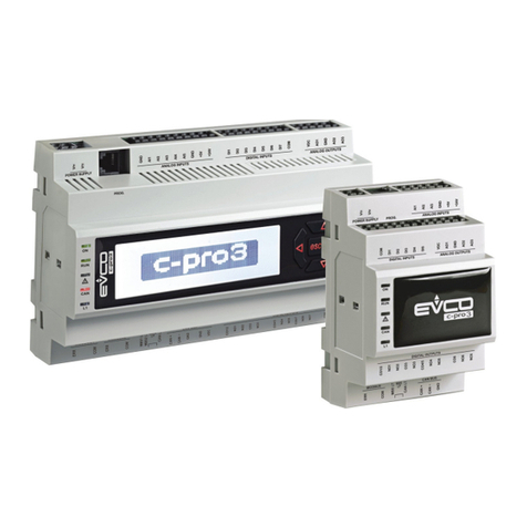
c-pro 3 giga Programmable controllers (28 I/O)
EN
ENGLISH
- blind open frame models or with enclosure
- power supply 115... 230 VAC
- clock
- 10 analogue inputs (can be configured also for dry contact digital input)
- 3 dry contact digital inputs
- 2 high voltage digital inputs
- 4 analogue outputs
- 9 electro-mechanical relay digital outputs
- TTL MODBUS port
- INTRABUS port (RS-485 MODBUS master/slave by connecting the serial interface
EVIF22ISX)
- RS-485 MODBUS slave port
- RS-485 port (MODBUS master/slave, BACnet MS/TP)
(1)
- CAN port
- USB port
- models with Ethernet port (MODBUS TCP, WebServer, BACnet IP)
(1)
(1) the BACnet communication protocol can be used only in alternative to the Web Server
function
Purchasing codes Version Power supply I/O Communication ports
EPG9O blind open frame
115... 230 VAC 28
TTL, INTRABUS,
2 RS-485, CAN and
USB
EPG9B
blind with
enclosure
EPG9OHX blind open frame TTL, INTRABUS,
2 RS-485, CAN, USB
and Ethernet
EPG9BHX
blind with
enclosure
1 MEASUREMENTS AND INSTALLATION
Measurements in mm (inches). To be fitted on a DIN rail, in a control panel.
To install the device operate as shown in pictures 1 and 2.
To remove the device, first remove any screw-in removable terminal blocks mounted in the
lower part, then operate as shown in pictures 3 and 4.
To install the device again press down the clip before.
INSTALLATION PRECAUTIONS
- Ensure that the working conditions are within the limits stated in the TECHNICAL
SPECIFICATIONS section
- Do not install the device close to heat sources, equipment with a strong magnetic field,
in places subject to direct sunlight, rain, damp, excessive dust, mechanical vibrations
or shocks
- In compliance with safety regulations, the device must be installed properly to ensure
adequate protection from contact with electrical parts. All protective parts must be
fixed in such a way as to need the aid of a tool to remove them.
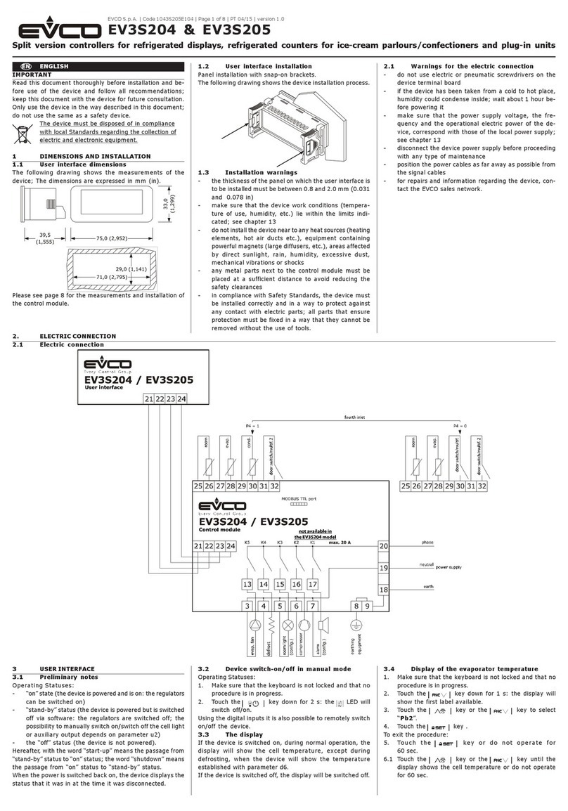
2 ELECTRICAL CONNECTION
N.B.
- Use cables of an adequate section for the current running through them
- To reduce any electromagnetic interference connect the power cables as far away
as possible from the signal cables and, if necessary, connect to a RS-485 MODBUS
network and/or a CAN network by using a twisted pair.
2.1 Connectors
Description of connectors.
N. DESCRIPTION
V~ device power supply (115... 230 VAC)
V~ device power supply (115... 230 VAC)
N. DESCRIPTION
DIHV1
high voltage digital input; DI1
DIHV2
high voltage digital input; DI2
COM high voltage digital inputs common contact
N. DESCRIPTION
NO1 K1 digital output normally open contact (3 A res. @ 250 VAC)
CO1 K1 digital output common contact
NO2 K2 digital output normally open contact (3 A res. @ 250 VAC)
CO2 K2 digital output common contact
NO3 K3 digital output normally open contact (3 A res. @ 250 VAC)
CO3 K3 digital output common contact
N. DESCRIPTION
NO4 K4 digital output normally open contact (3 A res. @ 250 VAC)
CO4 K4 digital output common contact
NO5 K5 digital output normally open contact (2 A res. @ 250 VAC)
CO5 K5 digital output common contact
NO6 K6 digital output normally open contact (3 A res. @ 250 VAC)
CO6 K6 digital output common contact
NO7 K7 digital output normally open contact (8 A res. @ 250 VAC)
CO7 K7 digital output common contact
N. DESCRIPTION
NO8 K8 digital output normally open contact (2 A res. @ 250 VAC)
CO8 K8 digital output common contact
NC9 K9 digital output normally closed contact
NO9 K9 digital output normally open contact (3 A res. @ 250 VAC)
CO9 K9 digital output common contact
N. DESCRIPTION
CAN+
signal + CAN port
CAN- signal - CAN port
A1/+ signal + RS-485 MODBUS slave port
B1/- signal - RS-485 MODBUS slave port
A2/+ signal + RS-485 port (MODBUS master/slave, BACnet MS/TP)
B2/- signal - RS-485 port (MODBUS master/slave, BACnet MS/TP)
IB data INTRABUS port
GND reference (GND)
12V power supply remote user interfaces (13 VDC)
The actual UNI-PRO 3.13 version implements a BACnet® standardized device profile B-ASC,
which doesn’t require the managing of Scheduler and Calendar objects, instead required for the
B-AAC profile.
N. DESCRIPTION
GND reference (GND)
DI3 digital input 3 (dry contact and for pulse trains up to 2 KHz); DI3
DI4 digital input 4 (dry contact and for pulse trains up to 2 KHz); DI4
DI5 digital input 5 (dry contact and for pulse trains up to 2 KHz); DI5
AI1
analogue input 1 (for PTC, NTC or Pt 1000 probes); AI1
can be configured also for dry contact digital input
AI2
analogue input 2 (for PTC, NTC or Pt 1000 probes); AI2
can be configured also for dry contact digital input
AI3
analogue input 3 (for PTC, NTC or Pt 1000 probes); AI3
can be configured also for dry contact digital input
AI4
analogue input 4 (for PTC, NTC or Pt 1000 probes); AI4
can be configured also for dry contact digital input
AI5
analogue input 5 (for PTC, NTC or Pt 1000 probes); AI5
can be configured also for dry contact digital input
N. DESCRIPTION
GND reference (GND)
AI6
analogue input 6 (for PTC, NTC or Pt 1000 probes, 0-5 V, 0-10 V, 0-20 mA or 4-20
mA transducers); AI6
can be configured also for dry contact digital input
AI7
analogue input 7 (for PTC, NTC or Pt 1000 probes, 0-5 V, 0-10 V, 0-20 mA or 4-20
mA transducers); AI7
can be configured also for dry contact digital input
AI8
analogue input 8 (for PTC, NTC or Pt 1000 probes, 0-5 V, 0-10 V, 0-20 mA or 4-20
mA transducers); AI8
can be configured also for dry contact digital input
AI9
analogue input 9 (for PTC, NTC or Pt 1000 probes, 0-5 V, 0-10 V, 0-20 mA or 4-20
mA transducers); AI9
can be configured also for dry contact digital input
AI10
analogue input 10 (for PTC, NTC or Pt 1000 probes, 0-5 V, 0-10 V, 0-20 mA or 4-20
mA transducers); AI10
can be configured also for dry contact digital input
+5V power supply 0-5 V ratiometric transducers (5 VDC)
VS power supply transducers (13 VDC)
N. DESCRIPTION
AO1 analogue output 1 (for 0-10 V or PWM)
AO2 analogue output 2 (for 0-10 V or PWM)
AO3 analogue output 3 (for 0-10 V or PWM)
AO4 analogue output 4 (for 0-10 V or PWM)
2.2 Electrical connection
Example of electrical connection.
2.3 Fitting the termination resistor of RS-485 networks and CAN network
To fit the termination resistor of the RS-485 network connected to the RS-485 MODBUS slave
port, place micro-switch MBS1LT in position ON.
To fit the termination resistor of the RS-485 network connected to the RS-485 port (MODBUS
master/slave, BACnet MS/TP), place micro-switch MBS2LT in position ON.
To fit the CAN network termination resistor, place micro-switch CANLT in position ON.
