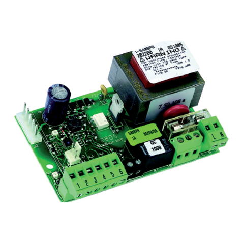
FAAC 844 MC-T User manual

12
ENGLISH ENGLISH
EC MACHINE DIRECTIVE COMPLIANCE DECLARATION
(DIRECTIVE 89/392 EEC, APPENDIX II, PART B)
Manufacturer: FAAC S.p.A.
Address: Via Benini, 1
40069 - Zola Predosa
BOLOGNA - ITALY
Hereby declares that: the 844 MC-T automation system
•is intended to be incorporated into machinery, or to be assembled with other
machinery to constitute machinery in compliance with the requirements of
Directive 89/392 EEC, and subsequent amendments 91/368 EEC, 93/44 EEC
and 93/68 EEC;
•complieswiththeessentialsafetyrequirements inthefollowingEECDirectives:
73/23 EEC and subsequent amendment 93/68 EEC.
89/336 EEC and subsequent amendments 92/31 EEC and 93/68 EEC.
and furthermore declares that unit must not be put into service until the
machineryintowhichitisincorporatedorofwhichitisacomponenthas been
identifiedanddeclaredtobeinconformitywith the provisions of Directive89/
392EECandsubsequentamendmentsenactedbythenationalimplementing
legislation.
Bologna, 1 January 1997
Managing
Director
A. Bassi

13
ENGLISH
ENGLISH
WARNING FOR THE INSTALLER
GENERAL SAFETY OBLIGATIONS
1) CAUTION! It is important for personal safety to follow all the instructions carefully. Incorrect installation or misuse of
the product may cause people serious harm.
2) Read the instructions carefully before starting to install the product.
3) Packagingmaterial(plastic,polystyrene,etc.)mustnotbe left within reachofchildrenas it is apotentialsourceof danger.
4) Keep the instructions in a safe place for future reference.
5) Thisproductwas designed and manufactured strictly for the use indicated inthisdocumentation.Anyothernotexpressly
indicated use may damage the product and/or be a source of danger.
6) FAAC accepts no responsibility due to improper use of the automation or use other than that intended.
7) Do not install the appliance in an area subject to explosion hazard: inflammable gasses or fumes are a serious safety
hazard.
8) Mechanical construction elements must meet the provisions of UNI8612, CEN pr EN 12604 and CEN pr EN 12605
Standards.
Toobtainan adequate level of safety in non EU countries, theabovementioned Standardsmustbeobservedin addition
to national standards.
9) FAAC will not accept responsibility if the principles of Good Workmanship are disregarded in constructing the closing
elements to be motorised, and if any deformation occurs during use of the said elements.
10) Installation must meet the following Standards: UNI8612, CEN pr EN 12453 and CEN pr EN 12635.
The safety class for the automation must be C+D.
11) Before carrying out any work on the system, switch off the power supply.
12) The mains power supply of the automation must be fitted with a all-pole switch with contact opening distance of 3mm
or greater. Use of a 6A thermal breaker with all-pole circuit break is recommended.
13) Make sure there is a differential switch with 0.03A threshold upstream of the system.
14) Check that the earthing system is correctly made and connect the closure metal parts to it. Also connect the Yellow/
Green wire of the automation to the earthing system.
15) The automation includes anintrinsicanti-crushingdeviceconsisting of a torque control which, however,mustbeinstalled
together with other safety devices.
16) Thesafety devices [e.g.: photocells, sensitive edges,etc…] protect anydangerous areas againstMovementmechani-
cal risks, such as, crushing, dragging, or shearing.
17) Use of at least one indicator-light is essential for each system (e.g.: FAAC LAMP MINILAMP, etc.) as well as a sign
adequately fixed to the frame structure, in addition to the devices mentioned at point “16”.
18) FAAC accepts no responsibility regarding safety and correct operation of the automation, should components made
by manufacturers other than FAAC be used in the system.
19) Use only FAAC original spare parts for maintenance.
20) Do not make any alterations to the components of the automation.
21) The installer must supply full information regarding manual operation of the system in case of an emergency and hand
to the user of the system the “User’s Guide” included with the product.
22) Do not allow children or other persons to stand near the product while in operation.
23) Keep remote controls or any other pulse generator well away from children, to prevent the automation from being
activatedaccidentally.
24) The user must refrain from attempting to repair or adjust the system personally and should contact qualified personnel
only.
25) Anything not expressly provided for in these instructions is not permitted.

14
ENGLISH ENGLISH
AUTOMATION 844 MC-T & 844 T Control unit
These instructions apply to the following model:
844MC-T
The FAAC mod. 844 MC-T automation for sliding gates is an
electromechanicaloperator powered bythree-phase voltage,
transmittingmotion to the sliding leaf via arackand pinion drive
suitably coupled to the gate.
The irreversible system ensures the gate is mechanically locked
whenthe motor is not operating and, therefore,nolock need to
be installed.
Thegearmotor issuppliedwithanadjustablemechanicalclutch,
providingthenecessary anti-crushing protection.
Aconvenient manualrelease makesit possibleto movethe gate
in the event of a power-cut or fault.
The 844 T (optional) electronic control unit must be housed in a
separate box.
The 844 MC-T automation is designed and manufactured to
control access of vehicles. Avoid any other use whatever.
1. DESCRIPTION AND TECHNICAL SPECIFICATIONS
MODEL 844 MC-T
Power supply 400V 3ph + N (+ 6 % - 10 %) 50Hz
Powerabsorption(W) 950
Reductionratio 1 ÷ 30
Number of pinion teeth Z16
Rack module 4 with 12.566 pitch
Max thrust (daN) 190 (Z16)
Max torque (Nm) 62
Thermalprotectionfor winding 135 °C
Use frequency 60 % (See graph)
Quantity of oil (I) 1,8
Type of oil FAAC XD 220
Ambient temperature range -20 ÷ +55 °C
Gearmotor weight (Kg) 15
Protectionclass IP 44
Max weight of gate (Kg) 2200 (Z16)
Gate speed (m/min) 9,5 (Z16)
Gate max length (time-out) 40m (Z16)
Clutch double disk in oil bath
Protective treatment cataphoresis
Appliance 844 T (optional)
Limit switch inductive sensor with plate
Gearmotoroverall dimensionsLxHxD(mm) see fig. 2
Technicalspecifications ofelectricmotor
RPM 1400
Powerconsumption (W) 950
Current absorption(A) 2,5
Powersupply 400V 3ph + N (+ 6 % - 10 %) 50Hz
Table1 TECHNICALSPECIFICATIONS OF 844 GEARMOTOR
1.1. MAXIMUM USE CURVE
Thecurve enables youtofind maximum worktime(T) according
to use frequency (F).
E.G: The 844 MC-T gearmotor can operate continuously at 60%
usefrequency.
Toensure efficientoperation,you haveto work inthe work range
under the curve.
Important: The curve is obtained at a temperature of 24°C.
Exposure to the sun’s rays can reduce use frequency down to
20%.
Calculation of use frequency
Thisis the percentage of effective worktime (opening + closing)
comparedto total cycle time (opening + closing + pause time).
Calculationformula:
Ta + Tc
%F = X 100
Ta + Tc + Tp + Ti
where:
Ta = opening time
Tc =closing time
Tp = pause time
Ti = interval time between one complete cycle and the next
Use frequency graph
Fig. 1
aSecuring corner plates
bPinion gear
cLimit inductive sensor
d844 INTERFACE card
eCover
fBreather screw
gAnti-crushing clutch
adjustment screw
hBore for accessing oil filling cap
iCover lock with triangular key
jOperator earthing connection
kRouting holes for connection cables
lLever release system
mProtective sides
10
20
30
40
50
60
70
80
90
100
012345678910
10 11 12
Percentuale
di lav. %
Tiem
p
o
(
h
)
% Duty cycle % Fréquence
d'utilisation
% Benutzungs-
frequenz
% Frecuencia
de utilización
Zeit
(
Std.
)
Tem
p
s
(
h
)
Time
(
h
)
Tem
p
o
(
h
)
b
a
c
d
e
f
g
h
i
j
k
l
m

15
ENGLISH
ENGLISH
a844 MC-T operator
bPhotocells
cKey switch
dFlashinglight
eRadioreceiver
f844 T elec.unit Fig. 3
2. DIMENSIONS
Fig. 2
Dimensionsinmm.
3. ELECTRICAL EQUIPMENT (standard system)
RSTN+ 400V 5x2,5 mm2
385
280
191
158
209
4. INSTALLATION OF AUTOMATION
4.1. PRELIMINARYCHECKS
To ensure safety and an efficient automation, make sure the
followingrequirements are met:
• The gate structure must be suitable for automation. In par-
ticular, wheel diameter must be in proportion to the weight
of the gate to be automated, an upper guide must be
supplied, and travel limit mechanical stops must be fitted to
prevent the gate from derailing.
• Thecharacteristics of thesoil must ensuresufficient stability of
the foundation plinth.
• There must be no pipes or electrical cables in the plinth
excavationarea.
• Ifthe gearmotor is exposed to passing vehicles, if possible, fit
adequate guards to protect against accidental impact.
• Check if an efficient earth plate is present for connection to
thegearmotor.
4.2. FOUNDATION PLATE MASONRY
1) Assemble the foundation plate as shown in Fig.4.
2) The foundation plate must be positioned as in Fig. 5 (right-
hand closure) or Fig. 6 (left-hand closure) to ensure the rack
and pinion mesh correctly.
3) Prepare a foundation plinth as in Fig.7 and enclose the
foundation plate in a wall providing one or more sheaths for
routing electric cables. Using a spirit level, check if the plate
is perfectly level. Allow the cement to set.
4) Lay the electrical cables for connection to the accessories
and power supply as in Fig.3.
To facilitate making connections, allow the cables to pro-
trude by about 45 cm from the hole (Fig.5-6 ref.) of the
foundation plate.
Fig. 4
Fig. 5
Fig. 6
225
90°
49
0÷50
49
0÷50 155
90°
63
11
11
1
11
11
1
Fig. 7

16
ENGLISH ENGLISH
4.3. MECHANICALINSTALLATION
1) Assemble thesecuringcorner platesand anti-vibration spac-
ers to the operator as shown in Fig. 8.
2) Open theoperator cover usingthe supplied triangularcavity
key as in Fig.9.
Thecover stays in open position bymeans of an appropriate
lockingsystem.
3) Place the operator on the plate using the supplied washers
and nuts as in Fig.10.
Whendoing this,route thecables through theraceway inthe
operator’slower half-body.
To access Interface card 844, route the cables through the
appropriate holes (Fig.1. ref.11), using the supplied cable
grippers.
4) Adjust height of the feet and distancefrom gate, consulting
Fig.11.
5) Secure thegearmotor tothe foundationplate,tightening the
nuts as shown in Fig.12.
6) Prepare the operator for manual operation as explained in
paragraph 7.
7) Remove and store the breather screw (Fig.13).
Fig. 11
Fig. 12
Fig. 9
Fig. 8
Fig. 10
4.4. INSTALLING THE RACK
4.4.1. STEEL RACK TO BE WELDED (Fig.14)
1) Fit the three threaded pawls on the
rack element, locating them in the
upper part of the slot. In this way,
play on the slot will accommodate
anyadjustments thatmaybe neces-
sary later on.
2) Manually place the leaf in closed
position.
3) Rest the first section of the rack level
onthe pinion gear, andweld the threaded pawlonthe gate
as shown in Fig.16.
4) Move the gate by hand, checking whetherthe rack rests on
the pinion gear, and weld the second and third pawl.
5) Position another rackelement nextto the previousone, using
a section of rack as in Fig.17, to synchronize the teeth of the
twoelements.
6) Move the gateby hand and weldthethree threaded pawls,
carrying on until you have covered the entire gate.
Fig. 14
Fig. 13
5 max
43
112 (Z16)
120 (Z20)
64
49
15 ÷ 32

17
ENGLISH
ENGLISH
This control unit can be installed in boxes E, L and LM. Before
securing the card in the box, fit the supplied support feet (long
for mod. E, short for models L and LM) in the 3 S-holes (Fig.20).
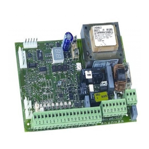
5.1.1. 844 T ELECTRONIC CONTROL UNIT
TABLE 2 844T TECHNICALSPECIFICATIONS
Power supply 400V 3ph+N (+6 -10 %) 50Hz
Motor max load 950 W
Accessories power supply 24Vdc
Accessories max load 500 mA
Warning light power supply 24V~ (5W max)
Ambient temperature range
- 20°C + 55°C
Fuses transformer primary winding
accessories
Quick-fit plugs - for decoding cards or RP receivers -
Inputs OPEN/PART OPEN/STOP/CLOSURE SAFETY DEVICES/
LIMIT-SENSORS
warning light
Outputs flashing light
motor
24Vdc accessories power supply
pause time (5-10-15-30-60-120-180 sec.)
Fig. 19
TF1
RL7 RL6
RL8
F1
F2
SW1
DS1
J1
J2
J3 J4 J5
A B STOP FSW FCC FCA
LK1
F1
SW1
J1
Led
LK1
J2 J5
RL6
RL8
RL7
J3 J4
DS1
F2
4.4.2. STEEL RACK TO BE BOLTED (Fig. 15)
1) Manually place the leaf in closed
position.
2) Rest the first section of the rack
levelon the pinion gear and insert
thespacer between the rack and
the gate, locating it in the upper
part of the slot.
3) Mark the drillingpoint on thegate.
Drill Ø 6.5 mm. and tap with a Ø 8
mm. taps. Tighten the bolt.
4) Move the gate by hand,checking whether the rack rests on
the pinion and repeat operations at point 3.
5) Position another rackelement nextto the previousone, using
a section of rack as in Fig. 17.
6) Move thegate byhand andexecute thesecuring operations
as done for the first element, carrying on until you have
covered the entire gate.
Fig. 15
Fig. 16
Fig. 17
Notes on the rack
• As the gate moves, make sure that no rack elements lose
contact with the pinion.
•Do not, repeat do not, weld the rack elements either to the
spacer or to each other.
• After installing the rack, to ensure correct meshing with the
pinion gear, we advise you to lower the position of the
gearmotorbyapproximately1.5mm
(Fig.18).
• Manually check that the gate
reachesthe mechanical limit stops
correctly, and that there is no fric-
tion during travel.
• Do not apply grease or other lubri-
cants between rack and pinion.
5. START-UP
5.1. CONNECTION TO ELECTRONIC CONTROL UNIT
ÜBefore attempting any work on the control unit (connections,
programming,maintenance),always turn off power supply.
Observe points 10, 11, 12, 13 and 14 of the GENERAL SAFETY
OBLIGATIONS.
Observing the instructions in Fig.3, lay the raceways and make
the electrical connections of the 844 T electronic unit to the
selectedaccessories.
Always separate power cables from control and safety cables
(push-button receiver,photocells,etc.).Topreventanyelectronic
noise whatever, use separate sheaths.
Fig. 18
Programming logics A1/A2/S1/S2/E1/E2/B/C
pre-flashing
Motor braking fixed
Safety timing 255 sec.
5.1.2. 844 T LAY-OUT
1.5
TABLE 3 844 T CONTROL UNIT COMPONENTS
F1 Fuse F1 5x20 F5A/250V rapid (transformer)
F2 Fuse F2 5x20 T1,6A/250V delayed (accessories)
SW1 RESET push-button
DS1 Programming microswitches
Led Input status signalling LEDs
J1 Quick-fit plug for decoding cards/RP receivers
J2 Low voltage terminal block for inputs/accessories
J3 Flashlight output terminal block (230V~ max 60W)
J4 Motor output terminal block
J5 Line power supply input terminal block
LK1 Bridge for warning light free contact
RL6-7 Motor relay
RL8 Braking relay

18
ENGLISH ENGLISH
5.1.3. ELECTRICALCONNECTIONS
5.2. DESCRIPTION
5.2.1. J1 PLUG
The J1 plug is used for rapid connection of cards MINIDEC,
DECODER, RP RECEIVERS (Fig. 21, 22, 23)
Fig. 20
ab
Warn.Light
24 Vac
5W max
FAACLAMP
MINILAMP
230 Vac
Altre sicurezze
Other safeties
Autres sécurités
Andere Sicherheiten
Otros disp. seg.
M
3Ph
NRST
OPEN A OPEN B STOP
1
2
1
2
3
4
5
1
2
3
4
5
1
2
FINECORSA
LIMIT SWITCH
FIN DE COURSE
ENDSCHALTER
FIN DE CARRERA
sure safety devices is to protect the gate movement
area during closing.
If the safety devices are tripped during closure, gate
movement is reversed, while they have no effect dur-
ing opening. If tripped when the gate is open or paus-
ing, closing safety devices prevent its closing.
To install several safety devices, connect the N.C.con-
tacts in series.
ÜIf closing safety devices are not connected, link
this input to the common contact (terminal 5) via a
jumper.
5 = Common contact for commands
6 = Common/negative of accessories power supply (-)
7 = 24 Vdc accessories power supply positive (+)
Max load of accessories is 500 mA.
To calculate absorption values, refer to the instruc-
tions for individual accessories.
9 = Warning light output (24 Vac)
The maximum load of the warning light is 5 W.
For instructions on operation of the warning light, con-
sult microswitches programming.
ÜIf you cut out jumper LK1, you obtain a voltage free
contact between terminals 8 and 9 (see fig.24).
400 Vac 3ph + N - 50 Hz
Fig. 23
Fig. 22Fig. 21
MINIDEC
SL/DS
PLUS
844MPS
DECODER
SL/SLP/DS
844MPS
844MPS
Installbyfitting theaccessory cardsso thattheir componentsside
faces the inside of the 844 T electronic appliance.
Insert and remove the cards after cutting power.
5.2.2. TERMINALBLOCKJ2(lowvoltage)
1 = OPEN A (N.O.) – Total opening
This is any pulse generator with N.O. contact which,
when activated, produces a gate opening movement.
In A, E and S logics, it commands both opening and
closing.
To install several Open A devices, connect N.O. con-
tacts in parallel.
2 = OPEN B (N.O.) – Pedestrians Opening / Closing
This is any pulse generator with N.O. contact which,
when activated in logics A, E and S, produces a gate
opening movement for pedestrians. In B and C logics,
it commands a closing movement.
To install several Open B devices, connect N.O.con-
tacts in parallel.
3 = STOP command (N.C.)
This is any device (e.g. a push-button) which, by open-
ing a contact, stops gate movement.
To install several stop devices, connect the N.C.con-
tacts in series.
ÜIf Stop devices are not connected, link the input to
the common contact (terminal 5) via a jumper.
4 = FSW closure safety devices contact (N.C.)
Safety devices are all devices (photocells, sensitive
edges, magnetic coils) with N.C. contact, which, if
there is an obstacle in the area they protect, operate
to interrupt gate movement. The purpose of the clo-
10 = 24 Vdc (+) power supply for inductive limit switch
11 = Limit switch common contact
12 = Opening limit switch (N.O.)
13 = Closing limit switch (N.O.)
N.B.: terminals 10-11-12-13 should be connected to the 844
INTERFACE card (supplied with gearmotor), observing
the diagram in Fig.20.
844 T 844 T 844 T
COMPLETE LK1 INTERRUPTEDLK1
(Freecontact)
Fig. 24
69
8
7
24V~ 5W max
9
8
2A max
S
SS
)

19
ENGLISH
ENGLISH
TABLE 4 STATUS OF LEDS
LED LIGHTED OFF
OPENA
commandactive command inactive
OPENB
commandactive command inactive
STOP
commandinactive command active
FSW
safetydevices disengaged safety devices engaged
FCC
closinglimitsensordisengaged closing limit sensor engaged
FCA
openinglimitsensordisengaged openinglimitsensor engaged
5.2.3. TERMINALBLOCKJ3(highvoltage)
Terminal board for connecting flashlight (max 60W).
5.2.4. TERMINALBLOCKJ4(highvoltage)
Terminal board for connection of motor.
5.2.5. TERMINALBLOCKJ5(highvoltage)
Terminal board for supplying 400V 3ph + Neutral - 50 Hz.
Connect the yellow-green earth cable as shown in Fig.25.
Fig. 25
ÜYou must press the RESET push-button after every program-
mingoperation.
Functionlogics
The following are available:
A1/A2 = “Automatic” S1/S2 =“Safety”
E1/E2/B = “Semi-automatic” C = “Deadman”
Operation of automation in the different logics is indicated in
Tables5-6-7-8-9-10-11-12.
Pausetime
Pausetimeis waitingtime inopen positionbeforere-closing when
an automatic logic was selected.
Pause times include pre-flashing if any
Operation of warning light
Usedtochange the appearance of the warning light at closing
by making it flash.
Pre-flashing
Flashinglightpre-flashing timeof5 secbeforeany movementcan
be selected. This warns anyone near the gate that it is about to
move.
5.3. PROGRAMMING
To program operation of automation, use the microswitches as
shown below.
1 2 3 4 5 6 7
Operation of warning light
Gate status
SW6 Closed Opening/Open Closing
ON
OFF
Light
Flashing
Light
Off Steady light
Pre-flashing (2)
SW7
Yes ON
No OFF
Logic SW1 SW2 SW3
E1 ON ON ON
B OFF ON ON
S2 ON OFF ON
E2 OFF OFF ON
A1 ON ON OFF
C OFF ON OFF
S1 ON OFF OFF
A2 OFF OFF OFF
Pause time (sec) (1)
Logic
A1-A2-S2 S1 SW4 SW5
515ONON
10 30 OFF O N
30 60 ON OFF
120 180 OFF OFF
ON
OFF
(1) Pause times include pre-flashing if any
(2) Pre-flashing begins 5” before every movement.
5.2.6.SIGNALLINGLEDs
6 LEDs are fitted on the card, indicating status of terminal block
inputs:
L
ED
LIGHTED
= contact closed
L
ED
OFF
= contact open
PULSES
LOGIC A1
SAFETY DEVICES
no effect
freezes pause until
disengagement
reverses motion
no effect
no effect
STOP
no effect
stops the count
stops
stops
no effect
GATE STATUS
CLOSED
OPEN FOR PAUSE
CLOSING
OPENING
STOPPED
OPENA-OPENB(1)
opens and closes
after pause time (2)
re-closes after 5"
(3)
reverses motion
no effect
re-closes (2)
TABLE 5 LOGIC A1 (AUTOMATIC)
TABLE 6 LOGIC A2 (AUTOMATIC PLUS)
PULSES
LOGIC A2
SAFETY DEVICES
no effect
when disengaged,
re-closes after 5”
stops and reverses at
disengagement(2)
no effect
no effect
STOP
no effect
stops the count
stops
stops
no effect
GATE STATUS
CLOSED
OPEN FOR PAUSE
CLOSING
OPENING
STOPPED
OPENA-OPENB(1)
opens and closes
after pause time (2)
re-closes after 5" (3)
reverses motion
no effect
re-closes (2)
TABLE 9 LOGIC E1 (SEMI-AUTOMATIC)
SAFETY DEVICES
no effect
no effect
reverses motion
no effect
no effect
GATE STATUS
CLOSED
OPEN
CLOSING
OPENING
STOPPED
OPENA-OPENB(1)
opens (2)
re-closes (2)
reverses motion
stops
re-closes (when safety devices
engaged, it re-opens) (2)
STOP
no effect
no effect
stops
stops
no effect
PULSES
LOGIC E1
LOGIC S1 PULSES
GATE STATUS
CLOSED
OPEN FOR PAUSE
CLOSING
OPENING
STOPPED
OPENA-OPENB(1)
opens and closes
after pause time (2)
closes immediately
(2-3)
reverses motion
reverses motion
re-closes (2)
STOP
no effect
stops the count
stops
stops
no effect
SAFETY DEVICES
no effect
when disengaged,
re-closes after 5”
reverses motion
no effect
no effect
TABLE 7 LOGIC S1 (SAFETY)
LOGIC S2
PULSES
STOP
no effect
stops the count
stops
stops
no effect
GATE STATUS
CLOSED
OPEN FOR PAUSE
CLOSING
OPENING
STOPPED
OPENA-OPENB(1)
opens and closes
after pause time (2)
closes immediately
(2-3)
reverses motion
reverses motion
re-closes (2)
SAFETY DEVICES
no effect
freezes pause until
disengagement
stopsandreversesat
disengagement(2)
no effect
no effect
TABLE 8 LOGIC S2 (SAFETY PLUS)

20
ENGLISH ENGLISH
1) Assemble the limitsensor centering theplate with respect to
the support threaded pins (Fig.26).
2) Power up automation.
3) Manually take thegate to opening position,leavingat least
2 cm from the travel limit mechanical stop.
4) Allow the plateto slide overthe rack inopening direction. As
soonastheFCALEDon the844Tcardgoesoff, movetheplate
forward by about 45 mm and secure it to the rack by
tighteningthe screws.
5) Manuallytake thegate to closing position,leave adistance
of about 2 cm from the travel limit stop mechanism.
6) Allow the plate to slide over the rack in closing direction. As
soon as the FCC LED on the 844 T card goes off, move the
plate forward by about 45 mm and secure it to the rack by
tighteningthe screws.
7) Re-lock the system (see paragraph 8).
8) Commandacomplete gatecycletocheck ifthelimit sensors
aretripping correctly.
N.B.:If the limit sensors are reversed(e.g. if the FCC LED goes
off when the gate is open), change over the cables con-
nected to the FCA and FCC inputs.
Notes on plate positioning
• Thedistance betweenlimit sensorsand platesmust be < 5mm
(Fig.11).
• Toavoid damaging the operator and/orinterrupting opera-
tion, leave a distance of least 2 cm from the travel limit
mechanicalstops.
5.7. ADJUSTING TRANSMITTED TORQUE
The 844 MC-T automation has an anti-crushing mechanical
clutch which (according to adjustment) limits the thrust of the
gate if it meets an obstacle.
Aftertheobstacle isremoved,the gaterestartsmoving eitheruntil
it reaches the limit sensor or when safety time has elapsed.
We advise you to set the torque limiter to conform to relevant
currentlaws.
Procedure for setting the tripping threshold of the anti-crushing
system:
1) Turn off power to the automation.
2) Remove the hole guard and fully unscrew the cover of the
clutch adjustment screw as shown in Fig.27.
(1) OPENBinputcommands partial opening.
(2) Withpre-flashingselected,movement begins after 5 sec.
(3) Ifthepulseis sent during pre-flashing, counting isrestarted.
(4) OPENB inputcommands closing.
(5) Push-buttonmustbe kept pressed to activategatemovement. When the
push-buttonis released,thegate stops.
5.4. FAULTCONDITIONS
Thefollowingconditionscausecertaineffectsto normaloperation
ofautomation:
amicroprocessorerror
bsafety electronic timing tripped (operation is interrupted if
continuous work time exceeds 255 sec. ).
climitsensorsdisconnected (or both engaged)
• Conditions aand bcause automation to stop.
•Condition ccauses an alarm situationdisabling any activity:
Normal operation can be restored only after eliminating the
alarmcause and pressing the RESET push-button (orturningoff
powersupply momentarily).
To have this condition signalled, the warning light must be
connected: the alarm is signalled by very rapidly flashing light
(0.25sec).
5.5. ROTATIONDIRECTIONCHECK
1) Release the operator, takeitmanually to mid-travel and re-
lock it (see par. 8).
2) Power up the system and then press the RESET push-button.
3) Give an Open commandtothe operator, check if the gate
moves in opening direction and then press the RESET push-
button to stop the leaf moving.
4) If rotationdirectionis incorrect, changeover wiring ofcables
T1 and T3 of the electric motor.
5.6. POSITIONING TRAVEL LIMIT PLATES
The 844 MT-C operator has inductive limit sensors (Fig.1 ref.3)
which, when they detect the movement of a plate secured to
the upper part of the rack, command gate movement to stop.
Procedure for correct positioning of the two supplied plates:
Fig. 26
TABLE 12 LOGIC C (DEADMAN)
TABLE10LOGIC E2 (SEMI-AUTOMATIC PLUS)
SAFETY DEVICES
no effect
no effect
stopsandreverses
atdisengagement(2)
no effect
no effect
GATE STATUS
CLOSED
OPEN
CLOSING
OPENING
STOPPED
OPENA-OPENB(1)
opens (2)
re-closes (2)
reverses motion
stops
re-closes (when safety devices
engaged, it re-opens) (2)
STOP
no effect
no effect
stops
stops
no effect
PULSES
LOGIC E2
TABLE 11 LOGIC B (SEMI-AUTOMATIC)
GATE STATUS
CLOSED
OPEN
CLOSING
OPENING
STOPPED
LOGIC B PULSES
OPEN A
opens ( (2)
no effect
no effect
no effect
completes
opening (2)
OPEN B (4)
no effect
closes(2)
no effect
no effect
completes
closing (2)
STOP
no effect
no effect
stopsmovement
stopsmovement
no effect
SAFETY DEVICES
no effect
prevents closing
stops movement
no effect
prevents closing
GATE STATUS
CLOSED
OPEN
CLOSING
OPENING
STOPPED
LOGIC C
OPEN A (5)
opens
no effect
no effect
completes
opening
OPEN B (4 e 5)
no effect
closes
no effect
completes
closing
SAFETY DEVICES
no effect
prevents closing
stopsmovement
no effect
prevents
closing
STOP
no effect
no effect
stopsmovement
stopsmovement
no effect
CONTROLS HELD DOWN CONTINUOUSLY
PULSES
21
ENGLISH
ENGLISH
Fig. 32
Fig. 33
Fig. 30
Fig. 31
3) Keep the motor shaft locked with the supplied lever and
adjust the clutch adjustment screw as in Fig. 28.
Fig. 27 Fig. 28
Fig. 29
Usingpressure, fittheside guardsof the operatorsecuring screws
(Fig.31).
Checkoperatingefficiencyofthe automationandallaccessories
connected to it.
Handthe “User’s Guide”to the Client, explaincorrect operation
anduseofthegearmotor, andindicatethepotentiallydangerous
areas of the automation.
7. MANUAL OPERATION
Ifthe gate has tobe operated manually intheevent of a power-
cutor fault to the automation, use thereleasedevice as follows:
1) Open the protectivedoor and fitthe supplied keyin the lock
(Fig.32).
2) Turn the key clockwiseand pull the release lever asshown in
Fig.33.
3) Open or close the gate manually.
To increase torque, turn the screw clockwise.
To reduce torque, turn the screw anti-clockwise.
ÜTheoperator issuppliedwith clutchsetto maximumvalue.
Therefore,youshould initially turn the screw anti-clockwise
toreachoptimum setting.
4) Power up the automation and check if the anti-crushing
systemoperates correctly.
ÜThe operator is supplied as standard with a clutch adjust-
ment spring for gates up to 1,000 Kg.
For heavier gates, use the alternative spring (also supplied).
To replace the spring, proceed as in Fig. 29.
6. AUTOMATION TEST
Afterinstallation, apply thedangerstickeronthetopof thecover
(Fig30).

22
ENGLISH ENGLISH
Fig. 34
8. RESTORING NORMAL OPERATING MODE
Toavoid aninvoluntary pulsefrom activatingthe gate duringthe
manoeuvre,before re-locking the operator, switch off powerto
thesystem.
1) Re-close the release lever.
2) Turn the key anti-clockwise.
3) Remove the key and close the lock protection door.
4) Move the gate until the release mechanism meshes.
9. SPECIAL APPLICATIONS
There are no special applications.
10.MAINTENANCE
When doing maintenance jobs, always check that the anti-
crushing clutch is correctly set, and that safety devices are
operatingefficiently.
10.1. TOPPING UP WITH OIL
Periodically check quantity of oil inside the operator.
Anannualcheck issufficient forlowto mediumusefrequency; for
heavier duty, check every 6 months.
To access the tank, temporarily remove the oil filling plug (Fig.1
ref.8).
Oilvisual check: oilmust nearly touchthe copper windingsof the
electricmotor (Fig. 34).
To top up, pour in oil up to the level indicated above.
Use only FAAC XD 220 oil and no other.
11.REPAIRS
For repairs, contact FAAC’s authorised Repair Centres.

23
ENGLISH
ENGLISH
Read the instructions carefully before using the product, and
keep them for future consultation.
GENERAL SAFETY REGULATIONS
If installed and used correctly, the 844 MC-T automation will
ensure a high degree of safety.
Somesimple rulesregarding behaviourwill avoidany accidental
trouble:
- Do not stand near the automation and do not allow children
andother peopleto standthere, especiallywhile it isoperating.
- Keep remote controls or any other pulse generator well away
fromchildren to preventtheautomation from beingactivated
involuntarily.
- Do not allow children to play with the automation.
- Donotwillingly obstruct gate movement.
- Prevent any branches or shrubs from interfering with gate
movement.
- Keepilluminated signalling systemsefficient and clearlyvisible.
- Do not attempt to activate the gate by hand unless you have
releasedit.
- In the event of malfunctions, release the gate to allow access
andwait for qualified technical personnel to dothenecessary
work.
- After enabling manual operating mode, switch off the power
supplyto the system before restoring normal operating mode.
- Do not make any alterations to the components of the auto-
mation.
- Donot attemptanykindofrepairofdirect actionwhatever and
contact qualified FAAC personnel only.
- Callin qualified personnel at least every6 months to check the
efficiency of the automation, safety devices and earth con-
nection.
DESCRIPTION
The844 MC-T automationis ideal forcontrolling industrial vehicle
accessareas.
The844MC-Tautomationforsliding gatesisanelectromechanical
operatorwhichtransmits movementtothe slidingleafvia apinion
with rack or chain appropriately coupled to the gate.
Operation of the sliding gate is controlled by electronic control
equipmenthoused in a container separatedfrom the operator.
When,with the gate closed, the controlequipment receives an
opening command by remote control or from another suitable
device, it activates the motor until the opening position is
reached.
If automatic operating mode was set, the gate closes auto-
matically after the selected pause time has elapsed.
Ifsemiautomaticoperating mode was set, a second pulse must
be sent to allow the leaves to close again.
Anopening pulseduring re-closing,always causes movementto
reverse.
A stop pulse (if supplied) always stops movement.
For details on sliding gate behaviour in different function logics,
consult the installation technician.
Automationsincludesafety devices(photocells, sensitiveedges)
that prevent the gate from closing when there is an obstacle in
the area they protect.
The system ensures mechanical locking when the motor is not
operating and, therefore, installing any lock is unnecessary.
Manual opening is, therefore, only possible by using the release
system.
Thegearmotorhas an adjustable mechanical clutch providing
thenecessaryanti-crushing protection.
Aninductive sensordetectstransitofmetalplatessecured onthe
rack,which correspondtothetravellimitpositions.The electronic
controlequipmentis housedina containerwhichis separatefrom
thegearmotor.
A handy manual release facility makes it possible to move the
gate in the event of a power cut or fault.
The warning-light indicates that the gate is currently moving.
MANUAL OPERATION
Ifthe gate has tobe operated manually intheevent of a power-
cut or automation fault, use the release device as follows:
1) Open the protectivedoor and fitthe supplied keyin the lock
(Fig.1).
2) Turn the key clockwiseand pull the release lever asshown in
Fig.2.
3) Open or close the gate manually.
RESTORING NORMAL OPERATION MODE
Toavoid aninvoluntary pulsefrom activatingthe gate duringthe
manoeuvre,before re-locking the operator, switch offpower to
thesystem.
1) Re-close the release lever.
2) Turn the key anticlockwise.
3) Remove the key and close the lock protection door.
4) Move the gate until the release mechanism meshes.
Fig. 1
Fig. 2
USER'S GUIDE
AUTOMATION 844 MC-T
Table of contents
Other FAAC Control Unit manuals