10
SCHEDA TECNICA
TECHNICAL CHART
www
.facsrl.com
-
[email protected] -
Ph.
+3
9
0444
9
7
6
2
4
1
F
AC-S
T_KA5
1
02
ED.
0
4/
IT_EN
(202
0)
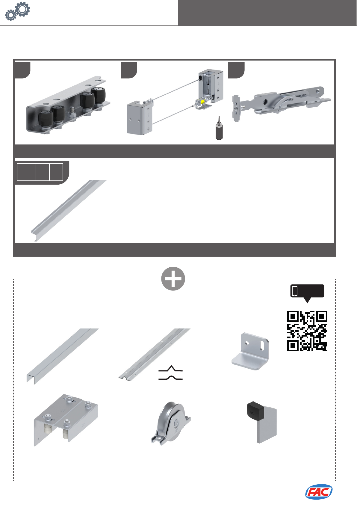
KIT TELESCOPICO MULTI-ANTA
MULTI-LEAF TELESCOPIC KIT
10
LATO/SIDE B
MANUTENZIONE
MAINTENANCE
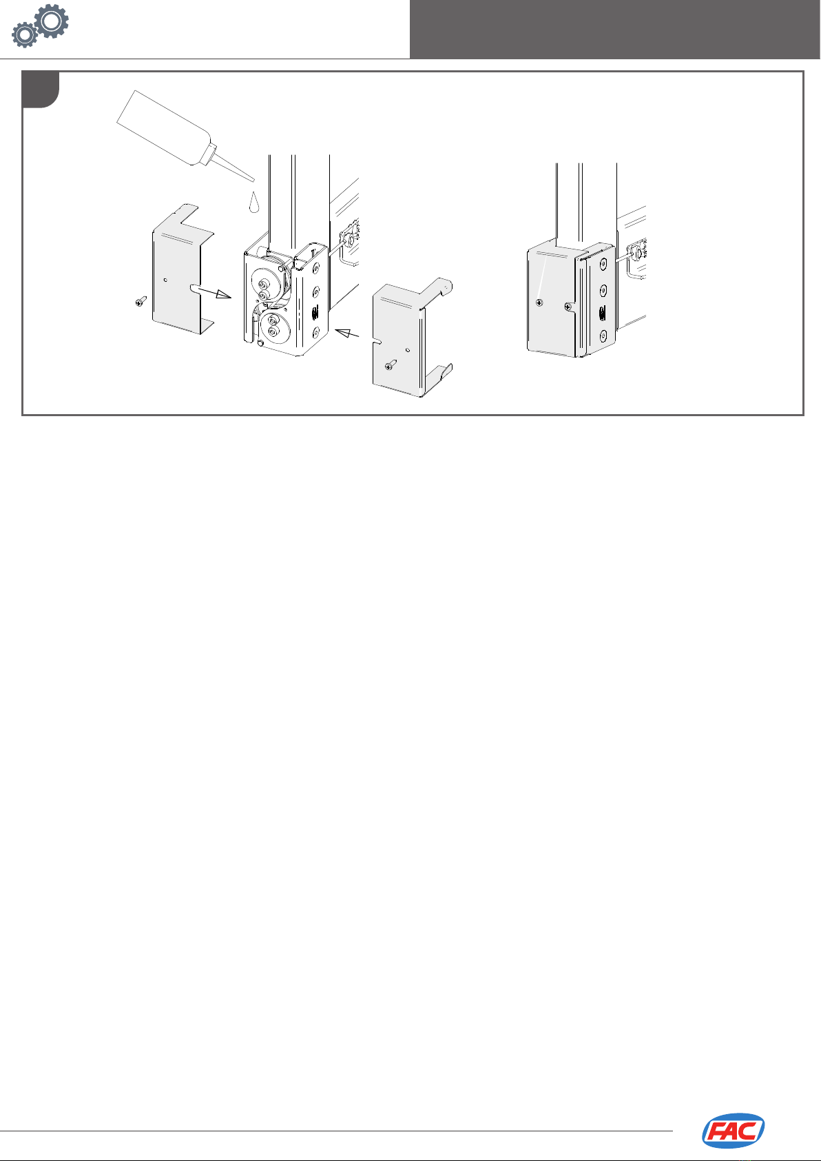
1. Eseguire le verifiche di funzionamento manuale a fine installazione; controllare periodicamente che il sistema sia correttamente
funzionante, privo di allentamenti e ben lubrificato (consigliato ogni tre mesi e massimo ogni 8000 cicli). Se necessario intervenire
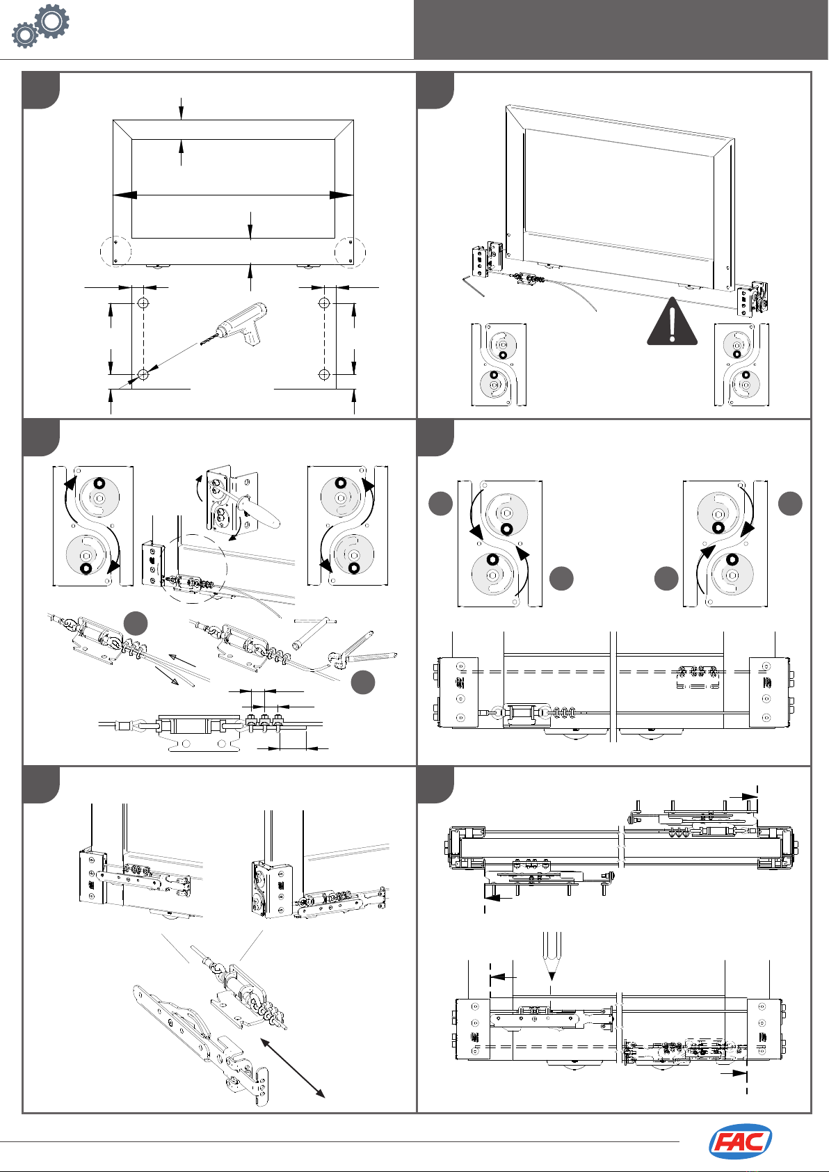
regolando il tensionamento e lubrificando la fune (vedi FIG. 19).
2. Nel caso in cui la fune risulti lenta rieseguire la procedura di tensionatura.
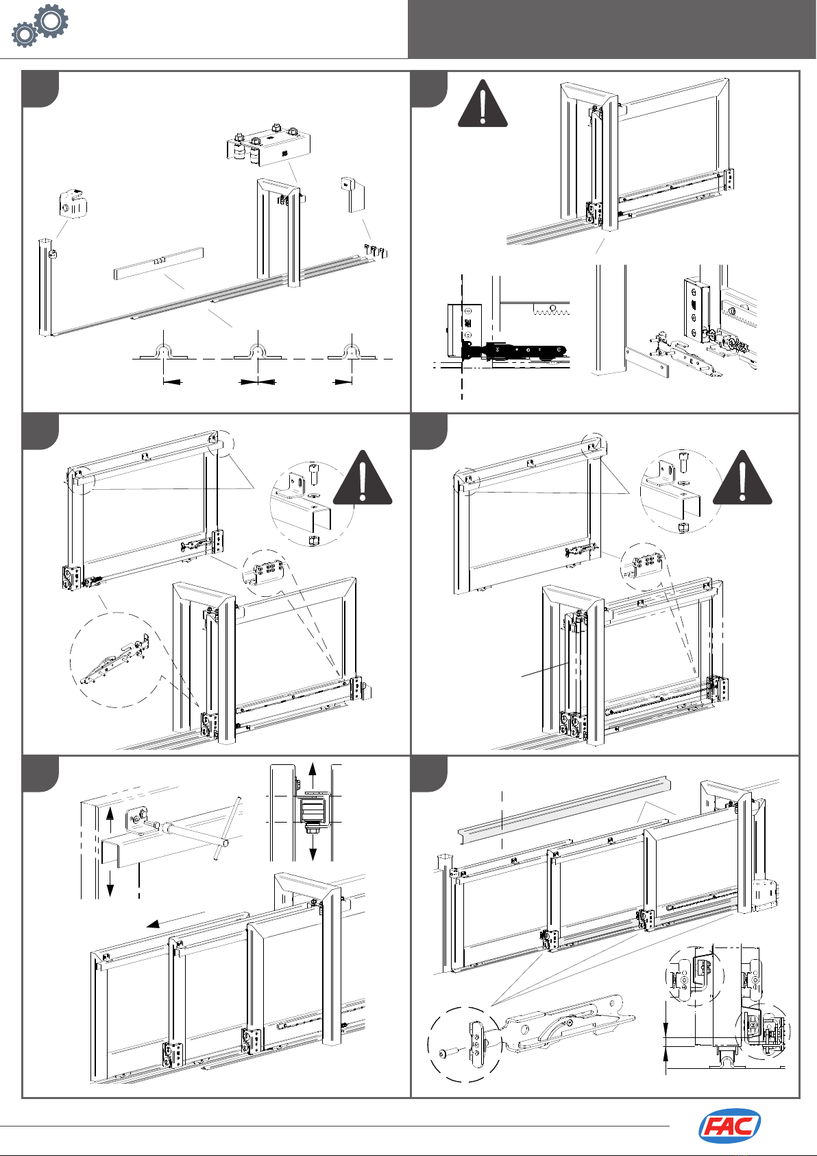
3. In caso di malfunzionamenti dovuti ad usura o urti accidentali, assicurarsi che tutti i componenti atti al sostegno del cancello
ed alla sua movimetazione siano integri, eventualmente procedere alla sostituzione.
4. L’utilizzo di questi articoli in ambienti particolarmente umidi, salini, acidi, polverosi o con temperature superiori a 120°C riduce
sensibilmente la durata dei cuscinetti e parti presenti negli articoli.
5. FAC garantisce il corretto funzionamento del sistema esclusivamente con l’utilizzo di ricambi originali.
Attenzione: Gli accessori compresi nei kit e l’installazione proposta fanno riferimento ad un esempio standard. Una installazione
non conforme alla procedura illustrata e/o l’omissione delle corretta manutenzione potrebbero causare malfunzionamenti,
compromettendo la sicurezza di persone e cose adiacenti. Verificare che gli accessori siano idonei all’opera specifica e dotarla
dei necessari dispositivi di sicurezza previsti dalle normative vigenti.
1. Perform all functioning inspections manually at the end of the installation; periodically check that the system is functioning, that
it is well lubricated and does not have any loosening (we suggest a full examination every 3 months or after 8000 cycles). If
necessary, adjust the tensioning of the cable and/or lubricate it.
2. If the cable is loose repeat the tensioning procedure.
3. In case of malfunctions due to wear or accidental impacts, make sure that all components apt to support the gate and its
maintenance are intact. If necessary, proceed with substitution.
4. The use of these items in harsh ambient conditions, such as: high humidity; high temperatures, salty, acid or dusty environments,
etc. significantly reduce the duration of the bearings and other parts.
5. FAC ensures the system correct functioning only using original spare parts.
Attention: The kit included accessories and the proposed installation make reference to a standard example. An installation
not in accordance with the illustrated procedure and the omission of the correct maintenance might compromise nearby things
and people’s security. Make sure that all accessories suit the specific work and make sure to use the necessary safety devices
provided by current regulations.
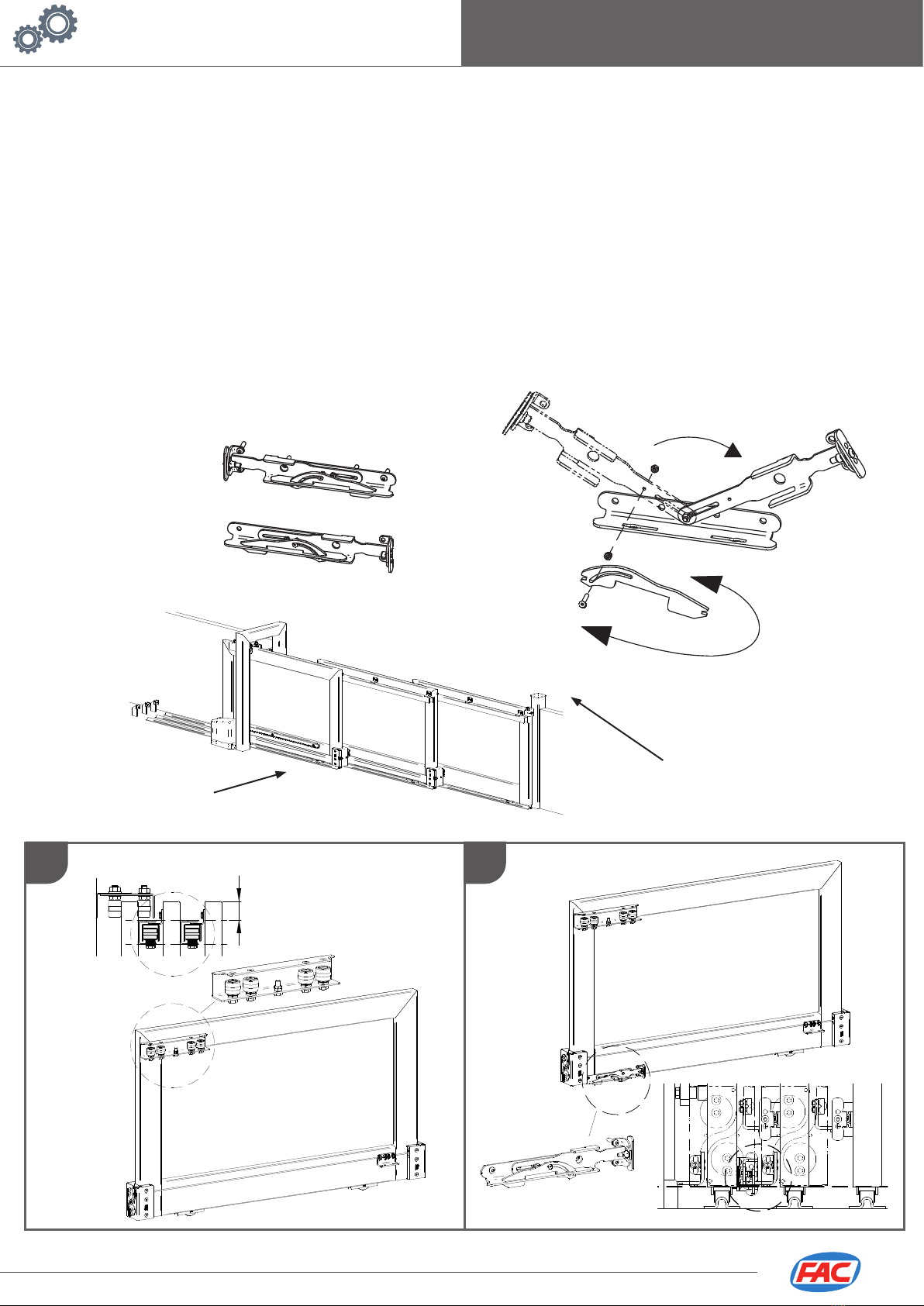
S2-S3
63
14
LATO/SIDE B
S1
DX
Sgancio DX
su colonna
Right hitch on
the column