Fanvil PA2 User manual

[键入文字]
PA2 SIP Video Intercom & Paging Gateway
User Manual V2.0

[键入文字]
Document VER
Firmware VER
Explanation
Time
V1.0
2.1.1.2924
Initial issue
20170804
V.2.0
2.1.1.2924
Increase the interface parameters, modify the company
address, increase the QIG IP scanning tool download
address
20171027

[键入文字]
Safety Notices
1. Please use the specified power adapter. If you need to use the power adapter provided by other
manufacturers under special circumstances, please make sure that the voltage and current provided is
in accordance with the requirements of this product, meanwhile, please use the safety certificated
products, otherwise may cause fire or get an electric shock.
2. When using this product, please do not damage the power cord either by forcefully twist it, stretch
pull, banding or put it under heavy pressure or between items, otherwise it may cause damage to the
power cord, lead to fire or get an electric shock.
3. Before using, please confirm that the temperature and environment is humidity suitable for the
product to work. (Move the product from air conditioning room to natural temperature, which may
cause this product surface or internal components produce condense water vapor, please open power
use it after waiting for this product is natural drying).
4. Please do not let non-technical staff to remove or repair. Improper repair may cause electric shock,
fire, malfunction, etc. It would lead to injury accident or cause damage to your product.
5. Do not use fingers, pins, wire, other metal objects or foreign body into the vents and gaps. It may
cause current through the metal or foreign body, which may even cause electric shock or injury
accident. If any foreign body or objection falls into the product please stop using.
6. Please do not discard the packing bags or store in places where children could reach, if children trap
his head with it, may cause nose and mouth blocked, and even lead to suffocation.
7. Please use this product with normal usage and operating, in bad posture for a long time to use this
product may affect your health.
8. Please read the above safety notices before installing or using this phone. They are crucial for the safe
and reliable operation of the device.

[键入文字]
Directory
I. Product introduction........................................................................................................................................
1. Appearance of the product..........................................................................................................................
2. Description...................................................................................................................................................
II. Start Using........................................................................................................................................................
1. Confirm the connection...............................................................................................................................
2. Quick Setting................................................................................................................................................
III. Basic operation...............................................................................................................................................
1. Answer a call.................................................................................................................................................
2. Call................................................................................................................................................................
3. End call..........................................................................................................................................................
4. Security linkage............................................................................................................................................
5. Video linkage................................................................................................................................................
IV. Page settings...................................................................................................................................................
1. Browser configuration.................................................................................................................................
2. Password Configuration...............................................................................................................................
3. Configuration via WEB.................................................................................................................................
(1) System......................................................................................................................................................
a) Information...........................................................................................................................................
b) Account..................................................................................................................................................
c) Configurations.......................................................................................................................................
d) Upgrade.................................................................................................................................................
e) Auto Provision.......................................................................................................................................
f) FDMS......................................................................................................................................................
g) Tools.......................................................................................................................................................
(2) Network...................................................................................................................................................
a) Basic.......................................................................................................................................................
b) VPN........................................................................................................................................................
(3) Line...........................................................................................................................................................
a) SIP..........................................................................................................................................................
b) Basic Settings........................................................................................................................................
(4) Intercom settings....................................................................................................................................
a) Features.................................................................................................................................................
b) Audio.....................................................................................................................................................

[键入文字]
c) Video......................................................................................................................................................
d) MCAST...................................................................................................................................................
e) Action URL.............................................................................................................................................
f) Time/Date..............................................................................................................................................
(5) Security settings......................................................................................................................................
(6) Function Key............................................................................................................................................
a) Function Key Settings............................................................................................................................
b) Advanced Settings.................................................................................................................................
V. Appendix..........................................................................................................................................................
1. Technical parameters...................................................................................................................................
2. Basic Functions.............................................................................................................................................

[键入文字]
6/43
I. Product introduction
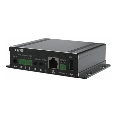
PA2 is a SIP video intercom & Paging device for industry application. The media stream transmission
adopts standard IP/RTP/RTSP protocol. It inherits the advantages of the stability and the sound
quality of FANVIL VOIP Phone. It is perfectly compatible with all the current SIP IPPBX /IMS platforms,
such as Asterisk, Broadsoft, 3CX, Elastix, etc. It has various functions and interfaces, Such as Intercom,
broadcast, video , security, recording, to adapt different application environment, you can very easy
to DIY your video intercom & paging equipment. PA2 is the best choice for everyone.
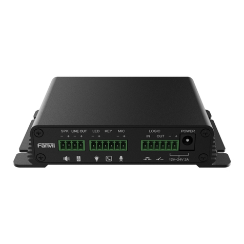
1. Appearance of the product
2. Description
⑪
⑨
10
①
⑧
③
②
④
⑤
⑥
⑦
⑭
⑮
⑬
⑫

[键入文字]
7/43
Label
Description
Label
Description
Label
Description
1
Speaker interface
2
Headset interface
3
LED interface
4
Function key interface
5
Microphone interface
6
Switch input interface
7
Switch output interface
8
Power input interface
9
Camera interface
10
Ethernet interface
⑪
Registration/Network LED
⑫
Volume control key
⑬
Restore factory key
⑭
Recording output interface
⑮
Grounding screw
II. Start Using
Before you start to use the equipment, please make the following installation.
1. Confirm the connection
Confirm whether the equipment of the power cord, network cable and the boot-up is normal. (Check
the network state of light
Handsets
Record 的
Speaker
Camera
switch
Call button
microphone
Infrared probe
Doorsensor
Emergency button
Warning
lights
Electric
lock
9
1
8
3
2
4
5
6
⑭
1

[键入文字]
8/43
Label
Explanation
1Speaker interface
according to the device input voltage adaptive output maximum power; 4Ω
speaker, POE / 10W, 12V / 10W, 18V / 20W, 24V / 30W. The greater the horn
impedance, the smaller the output power. Suggested wire diameter: 18AWG or larger
diameter.
2Headset interface
Speaker audio line signal output impedance 32 Ohm, single ended output voltage 1.2V,
used for external headphones or active speakers
3LED interface
Output 5V voltage 5 mA current, can be an external LED, indicating the network status,
call status, registration status.
4Function key interface
connection switch, you can log on page set the call number or IP address.
5Microphone interface
Recommend the use of 2.2K Ohm impedance electret condenser microphone,
sensitivity: -38dB, bias voltage 2.2V. Microphone signal cable it is recommended to use
a shielded cable and do not connect the shield cable to the grounding screw, improve
anti-interference.
6Switch input interface
Connect an infrared probe or emergency switch or Doorsensor and other switch
components.
7Switch output
interface
corresponding to the short-circuit input interface, login device security page settings,
you can control the alarm light, electric locks and other equipment; with the adjacent
⑧ power port connection for external equipment power supply.
8Power input interface
12V ~ 24V 2A input, according to the input voltage to determine the maximum output
power amplifier.
9Camera interface
standard RJ45 interface, connect the original camera, the proposed use of five or five
sub-network cable
10 Ethernet interface
WAN port, standard RJ45 interface, 10 / 100M adaptive, support POE input, it is
recommended to use five or super five network cable.
⑪Registration/Network
LED
indicates network status, call status, registration status. Fast flashing: network anomaly
or SIP account exception. Slow flashing: during a call. Always bright: successful
registration.
⑫Volume control key
standby to adjust the volume of the ringtone, call only adjust the call volume,
broadcast only adjust the broadcast volume. Long press the volume down key to
broadcast the IP address. Long press the volume plus key to switch the IP address
acquisition mode (specific operation see below search door phone).
⑬Restore factory key
press and hold for 3 seconds to flash the device to restart and restore the factory
settings.
⑭Recording output
interface
the local microphone voice and call voice mixed output, suitable for computer and
other equipment recording.

[键入文字]
9/43
⑮Grounding screw
external parts metal housing needs to be connected to this interface to prevent static
electricity and other interference caused the equipment to work abnormally.(Except
microphone accessories)
2. Quick Setting
The product provides a complete function and parameter setting. Users may need to have the
network and SIP protocol knowledge to understand the meaning all parameters represent. In order to
let equipment users enjoy the high quality of voice service and low cost advantage brought by the
device immediately, here we list some basic but necessary setting options in this section to let users
know how to operate device without understanding such complex SIP protocols.
In prior to this step, please make sure your broadband Internet can be normally operated, and
you must complete the connection of the network hardware. The product factory default network
mode is static IP address 192.168.1.128.
Press and hold volume down key for 3 seconds; the door phone would report the IP address by voice.
Or you can also use the "iDoorPhoneNetworkScanner.exe" software to find the IP address of the
device.(download address http://download.fanvil.com/tool/iDoorPhoneNetworkScanner.exe)
Long press the volume plus key for 10 seconds, the speaker issued a rapid beep, and then quickly
press the three volume plus the key, beep stopped. Wait 10 seconds, Successfully switch to dynamic
IP after the system automatically voice broadcast IP address. Switching again will become a fixed IP
address.
Note: when the device is powered on, 30s waiting is needed for device running.
Log on to the WEB device configuration.
In a line configuration page, service account, user name, server address and other parameters are
required for server address registration.
III.Basic operation
1. Answer a call
When a call comes in, the device would answer automatically. If you cancel auto answer feature and
set auto answer time, you would hear the ring at the set time and the device would auto answer

[键入文字]
10 /43
after configured timer.
2. Call
Configure Function key as hot key and then set up a number; after that you might press the Function
key for making call to the configured extension(s).
3. End call
Enable Release(You can set Function key to Release)key for hanging up feature to end call.
4. Security linkage
switch input interface received a door or emergency button and other sensor signals, the output
port connected to the alarm lights or electric locks and other equipment will automatically
respond to the server and send alarm information.
The output port defaults to the call automatically triggers the response and supports call
triggering with DTMF number triggering and short message triggering.
5. Video linkage
Use other manufacturers camera please connect to the switch, the device ⑨ interface can only
connect the original camera.
Landing page configuration camera user name, password, port number and other information. For
more information, please refer to the Video settings
IV.Page settings
1. Browser configuration
When the device and your computer are successfully connected to the network, you might enter the
IP address of the device in the browser as http://xxx.xxx.xxx.xxx/ and you can see the login interface of the
web page management.
Enter the user admin and password admin and click the Logon button to enter the settings screen.

[键入文字]
11 /43
2. Password Configuration
There are two levels of access: root level and general level. A user with root level can browse and
set all configuration parameters, while a user with general level can set all configuration parameters
except server parameters for SIP.
General level: It is not be set by default, you can add the feature when you need
User uses root level by default:
User name: admin
Password: admin
3. Configuration via WEB
(1) System
a) Information

[键入文字]
12 /43
Information
Field Name
Explanation
System
Information
Display equipment model, hardware version, software version, uptime, last uptime
MEMInfo and system time.
Network
Shows the configuration information of WAN port, including connection mode of WAN
port (Static, DHCP, PPPoE), MAC address, IP address of WAN port.
SIP Accounts
Shows the phone numbers and registration status of the 2 SIP LINES.
b) Account
Through this page, administrator can add or remove user accounts depend on their needs, or modify
existed user accounts permission.
Account
Field Name
Explanation
Change Web Authentication Password
You can modify the login password of the account
Add New User
You can add new user
User Accounts
Show the existed user accounts’ information

[键入文字]
13 /43
c) Configurations
Configurations
Field Name
Explanation
Export
Configurations
Save the equipment configuration to a txt or xml file. Please right click on the
choice and then choose “Save Link As.”
Import
Configurations
Find the config file, and press Update to load it to the equipment.
Reset to factory
defaults
PA2 would restore to factory default configuration and remove all configuration
information.
d) Upgrade
Upgrade
Field Name
Explanation

[键入文字]
14 /43
Software upgrade
Find the firmware, and press Update to load it to the equipment.
e) Auto Provision
Auto Provision
Field Name
Explanation
Common Settings
Current
Configuration
Version
Show the current config file’s version. If the config file to be downloaded is higher
than current version, the configuration would be upgraded. If the endpoints
confirm the configuration by the Digest method, the configuration would not be
upgraded unless it differs from the current configuration
General
Configuration
Version
Show the common config file’s version. If the configuration to be downloaded and
this configuration is the same, the auto provision would stop. If the endpoints
confirm the configuration by the Digest method, the configuration would not be
upgraded unless it differs from the current configuration.
CPE Serial Number
Serial number of the equipment
Authentication
Name
Username for configuration server. It is used for FTP/HTTP/HTTPS. If this is blank,
the phone would use anonymous access
Authentication
Password for configuration server. It is used for FTP/HTTP/HTTPS.

[键入文字]
15 /43
Password
Configuration File
Encryption Key
Encryption key for the configuration file
General
Configuration File
Encryption Key
Encryption key for common configuration file
Save Auto Provision
Information
Save the auto provision username and password in the phone until the server url
changed
DHCP Option
Option Value
The equipment supports configuration from Option 43, Option 66, or a Custom
DHCP option. It may also be disabled.
Custom Option
Value
Custom option number. It must be from 128 to 254.
SIP Plug and Play (PnP)
Enable SIP PnP
If it is enabled, the equipment would send SIP SUBSCRIBE messages to the server
address when it boots up. Any SIP server compatible with that message would
reply with a SIP NOTIFY message containing the Auto Provisioning Server URL
where the phones can request their configuration.
Server Address
PnP Server Address
Server Port
PnP Server Port
Transportation
Protocol
PnP Transfer protocol – UDP or TCP
Update Interval
Interval time for querying PnP server. Default is 1 hour.
Static Provisioning Server
Server Address
Set FTP/TFTP/HTTP server IP address for auto update. The address can be an IP
address or domain name with subdirectory.
Configuration File
Name
Specify configuration file name. The equipment would use its MAC ID as the
config file name if this is blank.
Protocol Type
Specify the Protocol type FTP, TFTP or HTTP.
Update Interval
Specify the update interval time. Default is 1 hour.
Update Mode
1. Disable – not to update
2. Update after reboot – update only after reboot.
3. Update at time period – update at periodic update period
TR069
Enable TR069
Enable/Disable TR069 configuration
ACS Server Type
Select Common or CTC ACS Server Type.
ACS Server URL
ACS Server URL.

[键入文字]
16 /43
ACS User
User name of ACS.
ACS Password
ACS Password.
TR069 Auto Login
Enable/Disable TR069 Auto Login.
INFORM Sending
Period
Time between transmissions of “Inform”; the unit is second.
f) FDMS
FDMS Settings
Enable FDMS
Enable/Disable FDMS configuration
FDMS Interval
The time to send sip Subscribe information to the FDMS server on a regular basis.
Unit seconds
Doorphone Info Settings
Community Name
The name of the community where the device is installed
Building Number
The name of the building where the equipment is installed
Room Number
The name of the room where the equipment is installed
g) Tools

[键入文字]
17 /43
Syslog is a protocol used to record log messages using a client/server mechanism. The Syslog server
receives the messages from clients, and classifies them based on priority and type. Then these messages
would be written into a log by rules which the administrator has configured.
There are 8 levels of debug information.
Level 0: emergency; System is unusable. This is the highest debug info level.
Level 1: alert; Action must be taken immediately.
Level 2: critical; System is probably working incorrectly.
Level 3: error; System may not work correctly.
Level 4: warning; System may work correctly but needs attention.
Level 5: notice; It is normal but significant condition.
Level 6: Informational; It is normal daily messages.
Level 7: debug; Debug messages normally used by system designer. This level can only be displayed
via telnet.
Tools
Field Name
Explanation
Syslog
Enable Syslog
Enable or disable system log.
Server Address
System log server IP address.
Server Port
System log server port.
APP Log Level
Set the level of APP log.
SIP Log Level
Set the level of SIP log.
Network Packets Capture
Capture a packet stream from the equipment. This is normally used to troubleshoot problems.
Reboot Phone

[键入文字]
18 /43
Some configuration modifications require a reboot to become effective. Clicking the Reboot button
would lead to reboot immediately.
Note: Be sure to save the configuration before rebooting.
(2) Network
a) Basic
Field Name
Explanation
Network Status
IP
The current IP address of the equipment
Subnet mask
The current Subnet Mask

[键入文字]
19 /43
Default gateway
The current Gateway IP address
MAC
The MAC address of the equipment
MAC Timestamp
Get the MAC address’s time.
Settings
Select the appropriate network mode. The equipment supports three network modes:
Static IP
Network parameters must be entered manually and would not change. All
parameters are provided by the ISP.
DHCP
Network parameters are provided automatically by a DHCP server.
PPPoE
Account and Password must be input manually. These are provided by
your ISP.
If Static IP is chosen, the screen below would appear. Enter values provided by the ISP.
DNS Server Configured by
Select the Configured mode of the DNS Server.
Primary DNS Server
Enter the server address of the Primary DNS.
Secondary DNS Server
Enter the server address of the Secondary DNS.
After entering the new settings, click the Apply button. The equipment would save the new settings and
apply them. If a new IP address was entered for the equipment, it must be used to login to the phone
after clicking the Apply button.
b) VPN
The device supports remote connection via VPN. It supports both Layer 2 Tunneling Protocol (L2TP)
and OpenVPN protocol. This allows users at remote locations on the public network to make secure
connections to local networks.

[键入文字]
20 /43
Field Name
Explanation
VPN IP Address
Shows the current VPN IP address.
VPN Mode
Enable VPN
Enable/Disable VPN.
L2TP
Select Layer 2 Tunneling Protocol
OpenVPN
Select OpenVPN Protocol. (Only one protocol may be activated. After the selection
Other manuals for PA2
2
Table of contents
Other Fanvil Gateway manuals

Fanvil
Fanvil PA2S Installation and user guide

Fanvil
Fanvil ATA User manual

Fanvil
Fanvil LINKVIL W712 User manual

Fanvil
Fanvil GA10 User manual

Fanvil
Fanvil PA3 User manual

Fanvil
Fanvil PA2S User manual

Fanvil
Fanvil G100S User manual

Fanvil
Fanvil G200S User manual

Fanvil
Fanvil PA2S Installation and user guide

Fanvil
Fanvil A1 User manual