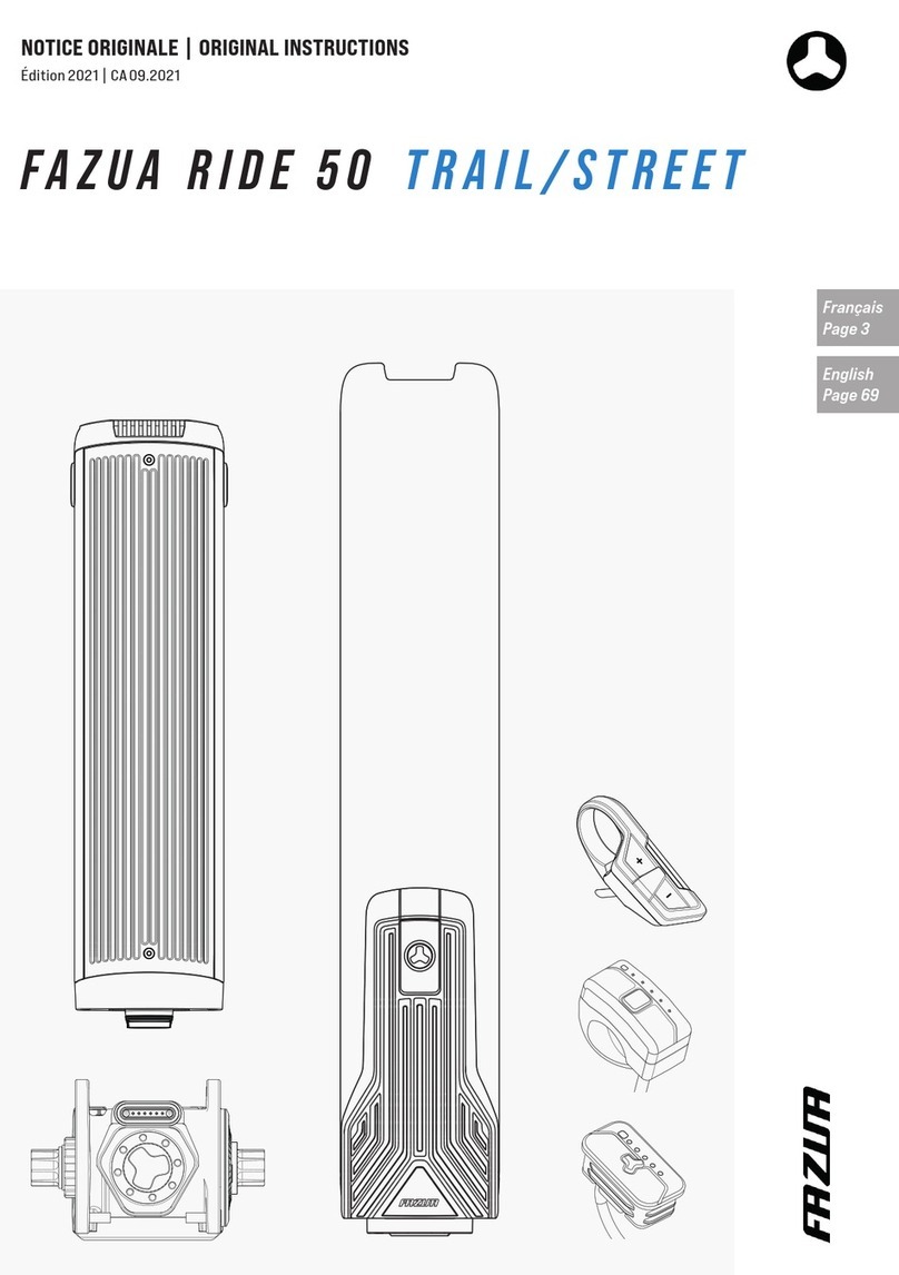
FAZUA RIDE 50 TRAIL/STREET User manual

FAZUA RIDE 50 TRAIL/STREET
ASSEMBLY INSTRUCTIONS
Edition 2021 | EN 09.2021

© 2021 Fazua GmbH
All Rights Reserved

Assembly instructions | English
3
BASICS
1 OVERVIEW: FAZUA RIDE 50 DRIVE SYSTEM ...............................................................................................4
1.1 FAZUA RIDE 50 components.......................................................................................................................4
1.2 Fastening elements and tools ...................................................................................................................5
2 ABOUT THESE ASSEMBLY INSTRUCTIONS..................................................................................................6
3 GENERAL SAFETY INSTRUCTIONS ............................................................................................................. 7
INSTALLATION AND REMOVAL OF THE COMPONENTS
4 REMOTE ...................................................................................................................................................8
4.1 Model differences.......................................................................................................................................8
4.2 REMOTE FX...................................................................................................................................................9
4.2.1 Mounting REMOTE FX...................................................................................................................................................... 9
4.2.2 Disassembling REMOTE FX.............................................................................................................................................11
4.3 REMOTE BX................................................................................................................................................. 12
4.3.1 Mounting REMOTE BX.....................................................................................................................................................12
4.3.2 Disassembling REMOTE BX............................................................................................................................................14
4.4 REMOTE RX................................................................................................................................................. 15
4.4.1 Mounting REMOTE RX.....................................................................................................................................................15
4.4.2 Disassembling REMOTE RX............................................................................................................................................17
5 LOCKER (LOCK IN FRAME) ...................................................................................................................... 18
5.1 Installing the LOCKER into the frame...................................................................................................... 18
5.2 Dismantling the LOCKER from the frame .............................................................................................. 20
6 SPEED SENSOR AND SPOKE MAGNET ...................................................................................................... 21
6.1 Attaching the speed sensor and spoke magnet.................................................................................... 21
6.2 Removing the speed sensor and spoke magnet ...................................................................................23
7 BOTTOM BRACKET .................................................................................................................................24
7.1 Installing the BOTTOM BRACKET..............................................................................................................24
7.2 Removing the BOTTOM BRACKET ............................................................................................................26
8 ACCESSORIES.........................................................................................................................................28
8.1 Cylinder lock (from chapter 5 "LOCKER").............................................................................................. 28
8.2 12 V connector box .................................................................................................................................. 28
8.2.1 Possible mounting locations on the e-bike ............................................................................................................... 28
8.2.2 Overview of the 12 V connector box........................................................................................................................... 29
8.2.3 Repairing the 12 V connector box ............................................................................................................................... 29
8.2.4 Retrofitting the 12 V connector box on the e-bike................................................................................................... 29

English | Assembly instructions
4
1 OVERVIEW: FAZUA RIDE 50 DRIVE SYSTEM
1.1 FAZUA RIDE 50 components
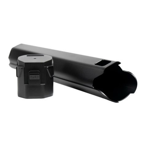
LOCKER
From Page 18
LOCKER PX
BOTTOM BRACKET
From Page 24
RIDE 50 BOTTOM BRACKET
REMOTE
From Page 8
REMOTE BXREMOTE FX REMOTE RX
SPEED SENSOR AND SPOKE MAGNET
From Page 21
DRIVEPACK AND BATTERY
ENERGY 250 X
RIDE 50 DRIVEPACK TRAIL/STREET

Assembly instructions | English
5
1.2 Fastening elements and tools
REMOTE FX
Provided screws:
none
Tool installation: Tool removal:
• Needle nose pliers • REMOTE FX removing tool
• Needle nose pliers
REMOTE BX
Provided screws:
• REMOTE screw (REMOTE BX screw)
Tool installation: Tool removal:
• Torque spanner
• Torx screwdriver T10
• Needle nose pliers
• Torx screwdriver T10
• Needle nose pliers
REMOTE RX
Provided screws:
• REMOTE screw (REMOTE RX screw)
Tool installation: Tool removal:
• Torque spanner
• Allen screwdriver 3 mm
• Needle nose pliers
• Allen screwdriver 3 mm
• Needle nose pliers
LOCKER PX
Provided screws:
• Locking screw (RIDE 50 screw lock mount)
Tool installation: Tool removal:
• Torx spanner T20
• Torque spanner
• RIDE 50 LOCKER adjustment plates if applicable
• RIDE 50 LOCKER adjustment device
(3 mm and 4 mm thickness), if applicable
• Torx spanner T20

English | Assembly instructions
6
BOTTOM BRACKET
Provided screws:
• Gear screws (RIDE 50 screw BB mount)
• Lockring
• Fixing screws of the BOTTOM BRACKET cover
Tool installation: Tool removal:
• Torx screwdriver T30
• Bottom bracket tool* 20 teeth
• Torque spanner
• Needle nose pliers
• Torx screwdriver T30
• Bottom bracket tool* 20 teeth
• Torque spanner
• Needle nose pliers
• Chain whip (optional)
• Crank puller tool ISIS** (optional)
* The bottom bracket tool must have a minimum inner diameter of 24.1 mm.
** The ISIS crank puller tool is only required if the e-bike does not have cranks with an integrated puller.
Speed sensor and spoke magnet
Provided screws:
• Fixing screw
• Spoke screw
Tool installation: Tool removal:
• Torx screwdriver T20
• Phillips screwdriver PH2
• Needle nose pliers
• Torque spanner
• Torx screwdriver T20
• Phillips screwdriver PH2
• Needle nose pliers
2 ABOUT THESE ASSEMBLY INSTRUCTIONS
These assembly instructions (hereinafter referred to as the “manual”) belong to the FAZUA RIDE 50 drive
system and are intended specifically for FAZUA dealers and trained specialist and service personnel.
The manual describes all the necessary steps to install the components of the drive system in the e-bike or
to remove the installed components from the e-bike.
The manual is expressly not designed for use by laypersons or as an alternative/supplement to the original
operating instructions.
To highlight hazards or risks, as well as important additional information within the manual, the following
markings are used:
WARNING
Risks that could result in death or serious injury are identified with the signal word “Warning”.
NOTICE
Risks relating to assembly errors or damage to the product are marked with the signal word “NOTE”.

Assembly instructions | English
7
Useful additional information is marked with this information symbol.
You can find out which tools you need for each step in the process at 1.2 “Fastening elements
and tools” on page 5.
Next to the torque spanner symbol, you will find information on the torque with which the
screws must be tightened for the respective work step.
3 GENERAL SAFETY INSTRUCTIONS
WARNING
There is a risk of accident and injury if the safety instructions are not observed!
If you do not observe the general safety instructions listed here, you can injure yourself and the
drive system or individual components can be damaged. Improperly mounted or damaged compo-
nents pose significant risks of accident and injury to the user of the e-bike.
►Never open any components of the drive system. The components of the FAZUA RIDE 50 drive
system may only be opened by FAZUA GmbH employees. Unauthorised opening will invalidate the
warranty claim and there is a risk of irreparable damage to the drive system.
►CAUTION! When fully assembling the drive system, the cable for the rear brake and the rear derail-
leur must always be laid first. Subsequently, the assembly of the drive system can be started.
Follow the sequence below when installing the components:
1. REMOTE (control unit)
2. LOCKER
3. Speed sensor
4. BOTTOM BRACKET
5. DRIVEPACK
►Only remove the BOTTOM BRACKET as instructed by the FAZUA Service Hotline.
►When replacing components mounted on the BOTTOM BRACKET and all other components of the
e-bike (e.g. chainring, pedals), only components of identical design or approved by the bicycle
manufacturer may be mounted.
►Clean and degrease all threads before screwing.
►Allow the threadlocker to cure for at least 6 hours after assembly.
►Follow the instructions for the individual steps to avoid assembly errors and damage to the
components.

English | Assembly instructions
8
INSTALLATION AND REMOVAL OF THE COMPONENTS
4 REMOTE
4.1 Model differences
The REMOTE for operating the FAZUA RIDE 50 drive system is available in different models:
REMOTE FX, REMOTE BX and REMOTE RX.
REMOTE FX
Attachment/position: Inserted into a designated slot in the top or downtube of the frame.
Available in the variants:
• RIDE 50 REMOTE FX 700
• RIDE 50 REMOTE FX 880
REMOTE BX
Attachment/position: Attached to the handlebar with a mounting clamp.
Available in the variants:
• RIDE 50 REMOTE BX 22/1200
• RIDE 50 REMOTE BX 22/1400
REMOTE RX
Attachment/position: Attached to the handlebar with a mounting clamp.
Available in the variant:
• RIDE 50 REMOTE RX 1200

Assembly instructions | English
9
4.2 REMOTE FX
4.2.1 Mounting REMOTE FX
NOTICE
►Make sure that the REMOTE cable is not kinked or under tension.
►Make sure to lay the cables according to the manufacturer's specifications (cable routing, cable
tie holders, etc.).
►Be careful not to damage the rubberised surface when installing the REMOTE FX and do not press
the centre button when inserting the REMOTE FX.
►Always use needle-nose pliers to insert the plugs straight into the corresponding connection.
Be careful not to twist or bend the connectors.
►Be sure to follow the specified connections for the speed sensor and REMOTE connectors.
Be careful not to insert the plugs into the wrong socket. The connector of the speed sensor and
the corresponding slot on the BOTTOM BRACKET are marked in green.
The slot for the REMOTE FX in the manufacturer-specific e-bike frame is provided either in
the top or downtube. It is also possible to retrofit a e-bike with the REMOTE FX. For retrofit-
ting the REMOTE FX, only the slot in the downtube is used.
Depending on the manufacturer-specific e-bike frame, you might have to remove the LOCKER
and the BOTTOM BRACKET in order to lead the REMOTE cable through the frame.
Step 1: Preparing REMOTE FX
→
Grease the rubber lips of the REMOTE FX with silicone grease before inserting it to prevent the sealing
lips from breaking during installation and the REMOTE from repeatedly sliding up out of the slot.
The amount of silicone grease to be used varies between manufacturer-specific e-bike
frames and depends on how tightly the REMOTE FX sits in the specified slot in the frame.
Step 2: Inserting REMOTE FX into the slot
Depending on the manufacturer-specific e-bike model, the REMOTE FX must first be inserted
into the adapter (optionally available from FAZUA) during initial installation before the REMOTE
FX is inserted into the slot.
→
Guide the REMOTE cable from the corresponding slot through the e-bike frame to the BOTTOM BRACKET.
Lay the cable according to the manufacturer's specifications.
→
Insert the REMOTE FX into its slot from above and
carefully press it into the frame.
When pressing the REMOTE FX into the slot, take
care not to damage the rubberised surface. Also
note that only the upper and lower sections are
pressed and not the centre button.

English | Assembly instructions
10
Step 3: Connecting REMOTE FX to the BOTTOM BRACKET
→
If necessary, reinstall the LOCKER and the BOTTOM BRACKET if you have previously removed the parts to
route the REMOTE cable through the frame.
Grease the sealing ring of the connectors (highlighted in colour) with a little silicone grease
before inserting it into the connector to make it easier to insert. Make sure to grease only
the sealing ring and not the entire plug.
Note the arrow mark on the plug and
the notch on the connector to insert
the plug into the slot correctly aligned.
→
Insert the REMOTE connector (2) into the centre
connector on the BOTTOM BRACKET using the
needle-nose pliers.
The green marked left connection (in driving
direction) is intended for the green marked plug
of the speed sensor (3).
3
2
If no other accessories are fitted to
the e-bike, the right-hand connec-
tion on the BOTTOM BRACKET remains
unoccupied.
→
Make sure that the connection (4),
which may be free, is closed with a
cap for the BOTTOM BRACKET.
4
Step 4: Checking REMOTE functions with FAZUA Toolbox
→
Finally, carry out a diagnosis with the FAZUA toolbox and check that all functions are working correctly.

Assembly instructions | English
11
4.2.2 Disassembling REMOTE FX
NOTICE
►Always use needle-nose pliers to pull the plugs straight out of the corresponding connection.
Be careful not to twist or bend the connectors.
►When dismantling the REMOTE FX, work carefully so as not to damage the paint on the e-bike
frame.
Step 1: Disconnecting the REMOTE cable from the BOTTOM BRACKET
→
Pull the REMOTE connector (2) out of the centre
connector on the BOTTOM BRACKET using the
needle-nose pliers.
2
Step 2: Removing REMOTE FX from the slot
When dismantling the REMOTE FX, the presence of the adapter depends on the original
mounting method. If an adapter is available, it is removed together with the REMOTE FX and
reinstalled in the same way.
→
CarefullyremovetheleveroftheREMOTEFXfromthe
frame using the REMOTE FX removing tool (5).
The REMOTE FX removing tool is available from
the FAZUA online shop.
If the REMOTE FX is installed in the downtube, you
can alternatively (after removing the LOCKER)
carefully push it out of its slot from the inside of
the downtube.
5
Step 3: Remove the REMOTE cable from the e-bike frame if necessary
Depending on the manufacturer-specific e-bike frame, you might have to remove the LOCKER
and the BOTTOM BRACKET in order to lead the REMOTE cable through the frame.
→
If necessary, pull the REMOTE cable out of the frame (make sure that all cable fasteners in the frame are
loosened beforehand).

English | Assembly instructions
12
4.3 REMOTE BX
4.3.1 Mounting REMOTE BX
NOTICE
►Make sure that the REMOTE cable is not kinked or under tension.
►Make sure to lay the cables according to the manufacturer's specifications (cable routing, cable
tie holders, etc.).
►Always use needle-nose pliers to insert the plugs straight into the corresponding connection.
Be careful not to twist or bend the connectors.
►Be sure to follow the specified connections for the speed sensor and REMOTE
connectors. Be careful not to insert the plugs into the wrong socket.
The connector of the speed sensor and the corresponding slot on the BOTTOM BRACKET are
marked in green.
The REMOTE BX can only be mounted on handlebars with a diameter of 22 mm.
Depending on the manufacturer-specific e-bike frame, you might have to remove the LOCKER
and the BOTTOM BRACKET in order to lead the REMOTE cable through the frame.
Step 1: Mounting the REMOTE BX on the handlebar
→
Slide the REMOTE BX onto the handlebar from the
outside (preferably from the left side).
or
→
Open the fastening clamp by bending it open
and place the REMOTE BX on the handlebar from
above.
Be careful not to damage the cable when bending
it open.
→
Tighten the REMOTE screw (REMOTE BX screw) (1)
with the Torx screwdriver T10 to fix the REMOTE
BX to the handlebar.
The REMOTE BX must be firmly and securely
attached. Also make sure to align the REMOTE BX
sensibly so that the e-bike rider can comfortably
operate the REMOTE BX while riding.
1.0–1.5 Nm
1

Assembly instructions | English
13
Step 2: Connecting the REMOTE BX to the BOTTOM BRACKET
→
Feed the REMOTE cable from REMOTE BX through the e-bike frame to the BOTTOM BRACKET.
→
If necessary, reinstall the LOCKER and the BOTTOM BRACKET if you have previously removed the parts to
route the REMOTE cable through the frame.
Grease the sealing ring of the connectors (highlighted in colour) with a little silicone grease
before inserting it into the connector to make it easier to insert. Make sure to grease only
the sealing ring and not the entire plug.
Note the arrow mark on the plug and
the notch on the connector to insert
the plug into the slot correctly aligned
→
Insert the REMOTE connector (2) into the centre
connector on the BOTTOM BRACKET using the
needle-nose pliers.
The green marked left connection (in driving
direction) is intended for the green marked plug
of the speed sensor (3).
3
2
If no other accessories are fitted to
the e-bike, the right-hand connec-
tion on the BOTTOM BRACKET remains
unoccupied.
→
Make sure that the connection (4),
which may be free, is closed with a
cap for the BOTTOM BRACKET.
4
Step 3: Checking REMOTE functions with FAZUA Toolbox
→
Finally, carry out a diagnosis with the FAZUA toolbox and check that all functions are working correctly.

English | Assembly instructions
14
4.3.2 Disassembling REMOTE BX
NOTICE
►Always use needle-nose pliers to pull the plugs straight out of the corresponding connection.
Be careful not to twist or bend the connectors.
Step 1: Disconnecting the REMOTE cable from the BOTTOM BRACKET
→
Pull the REMOTE connector (2) out of the centre
connector on the BOTTOM BRACKET using the
needle-nose pliers.
2
Step 2: Dismantling REMOTE BX from handlebars
→
Loosen the REMOTE screw (REMOTE BX Screw) (1)
on the underside of the REMOTE BX with the Torx
screwdriver T10.
1
→
Slide the REMOTE BX outwards off the handlebar.
or
→
Remove the REMOTE BX from the handlebar
by bending up the mounting clip.
Be careful not to damage the cable when bending
open the fixing clip.
Step 3: Remove the REMOTE cable from the e-bike frame if necessary
Depending on the manufacturer-specific e-bike frame, you might have to remove the LOCKER
and the BOTTOM BRACKET in order to lead the REMOTE cable through the frame.
→
If necessary, pull the REMOTE cable out of the frame (make sure that all cable fasteners in the frame are
loosened beforehand).

Assembly instructions | English
15
4.4 REMOTE RX
4.4.1 Mounting REMOTE RX
NOTICE
►Make sure that the REMOTE cable is not kinked or under tension.
►Make sure to lay the cables according to the manufacturer's specifications (cable routing, cable
tie holders, etc.).
►Always use needle-nose pliers to insert the plugs straight into the corresponding connection.
Be careful not to twist or bend the connectors.
►Be sure to follow the specified connections for the speed sensor and REMOTE connectors.
Be careful not to insert the plugs into the wrong socket. The connector of the speed sensor and
the corresponding slot on the BOTTOM BRACKET are marked in green.
The REMOTE RX can only be mounted on handlebars with a diameter of 31.8 mm.
Depending on the manufacturer-specific e-bike frame, you might have to remove the LOCKER
and the BOTTOM BRACKET in order to lead the REMOTE cable through the frame.
Step 1: Mounting the REMOTE RX on the handlebar
→
Slide the REMOTE RX onto the handlebar from the
outside (preferably from the left side).
or
→
Open the fastening clamp by bending it open
and place the REMOTE RX on the handlebar from
above.
Be careful not to damage the cable when bending
it open.
→
Tighten the REMOTE screw (REMOTE RX Screw)
(1) 3 mm with the Allen screwdriver to fix the
REMOTE RX to the handlebar.
The REMOTE RX must be firmly and securely
attached. Also make sure to align the REMOTE RX
sensibly so that the e-bike rider can comfortably
operate the REMOTE RX while riding.
1.0–1.5 Nm
1

English | Assembly instructions
16
Step 2: Connecting the REMOTE RX to the BOTTOM BRACKET
→
Feed the REMOTE cable from REMOTE RX through the e-bike frame to the BOTTOM BRACKET.
→
If necessary, reinstall the LOCKER and the BOTTOM BRACKET if you have previously removed the parts to
route the REMOTE cable through the frame.
Grease the sealing ring of the connectors (highlighted in colour) with a little silicone grease
before inserting it into the connector to make it easier to insert. Make sure to grease only
the sealing ring and not the entire plug.
Note the arrow mark on the plug and
the notch on the connector to insert
the plug into the slot correctly aligned
→
Insert the REMOTE connector (2) into the centre
connector on the BOTTOM BRACKET using the
needle-nose pliers.
The green marked left connection (in driving
direction) is intended for the green marked plug
of the speed sensor (3).
3
2
If no other accessories are fitted to
the e-bike, the right-hand connec-
tion on the BOTTOM BRACKET remains
unoccupied.
→
Make sure that the connection (4),
which may be free, is closed with a
cap for the BOTTOM BRACKET.
4
Step 3: Checking REMOTE functions with FAZUA Toolbox
→
Finally, carry out a diagnosis with the FAZUA toolbox and check that all functions are working correctly.

Assembly instructions | English
17
4.4.2 Disassembling REMOTE RX
NOTICE
►Always use needle-nose pliers to pull the plugs straight out of the corresponding connection.
Be careful not to twist or bend the connectors.
Step 1: Disconnecting the REMOTE cable from the BOTTOM BRACKET
→
Pull the REMOTE connector (2) out of the centre
connector on the BOTTOM BRACKET using the
needle-nose pliers.
2
Step 2: Dismantling REMOTE RX from handlebars
→
Loosen the REMOTE screw (REMOTE RX Screw) (1)
on the underside of the REMOTE RX with the 3 mm
Allen screwdriver.
1
→
Slide the REMOTE RX outwards off the handlebar.
or
→
Remove the REMOTE RX from the handlebar
by bending up the mounting clip.
Be careful not to damage the cable when bending
open the fixing clip.

English | Assembly instructions
18
Step 3: Remove the REMOTE cable from the e-bike frame if necessary
Depending on the manufacturer-specific e-bike frame, you might have to remove the LOCKER
and the BOTTOM BRACKET in order to lead the REMOTE cable through the frame.
→
If necessary, pull the REMOTE cable out of the frame (make sure that all cable fasteners in the frame are
loosened beforehand).
5 LOCKER (LOCK IN FRAME)
The LOCKER designates the lock for the DRIVEPACK on the frame.
5.1 Installing the LOCKER into the frame
→
If necessary, remove the DRIVEPACK from its holder on the e-bike frame before you start
installing the LOCKER.
Step 1: Inserting the cylinder lock (optional)
The equipment with a cylinder lock is optional and depends on the bicycle manufacturer.
The cylinder lock is not included in the scope of delivery of the drive system and cannot be
retrofitted if no space is provided in the frame for the cylinder lock.
→
Skip this step if no cylinder lock is to be installed in the LOCKER.
→
Push the cylinder lock (7) as far as possible into
the corresponding holder on the LOCKER so that
the cylinder lock engages in the holder.
Make sure that the cylinder lock is open when you
insert it into the slot on the LOCKER.
7
Step 2: Inserting and fixing LOCKER into the frame
→
Insert the LOCKER into its holder on the e-bike
frame.
→
Tighten the locking screws (RIDE 50 Screw Lock
Mount) (8) with the Torx screwdriver T20.
1.8–2.2 Nm
8

Assembly instructions | English
19
Step 3: Checking the gap dimension / measuring existing tolerances if necessary
Due to its design, the LOCKER not only holds the DRIVEPACK securely in the e-bike frame,
but also creates a preload between the DRIVEPACK and the BOTTOM BRACKET.
If the required preload is not guaranteed (e.g. due to
excessive tolerances in the frame), faults may occur
in the electrical connection and the preload must be
created by inserting the RIDE 50 LOCKER adjustment
plates (11) included in the scope of delivery. These
RIDE 50 LOCKER adjustment plates are installed with
the LOCKER and reduce the distance between the
LOCKER and DRIVEPACK in mm increments.
11
12
→
Insert the DRIVEPACK into the e-bike.
→
Measure the distance between LOCKER and
DRIVEPACK with the RIDE 50 LOCKER adjustment
device (12) or a feeler blade gauge.
The RIDE 50 LOCKER adjustment device is avail-
able in two thicknesses (3 mm and 4 mm thick-
ness), start with the thinner RIDE 50 LOCKER
adjustment device (3 mm).
12
Measurement results and further procedure
No RIDE 50 LOCKER adjustment device fits in the
gap. There is no need to insert a LOCKER adjustment
plate.
→
Go to Step 6 “Inserting the Ride 50 lock cylinder”
on page 20.
The 3 mm RIDE 50 LOCKER adjustment device fits in
the gap, while the 4 mm RIDE 50 LOCKER adjustment
device does not.
→
Get a LOCKER adjustment plate ready and proceed
to Step 4 “Removing the LOCKER to insert the
LOCKER adjustment plate” on page 19.
The 4 mm RIDE 50 LOCKER adjustment device fits
in the gap.
→
Prepare two LOCKER adjustment plates and
proceed to Step 4 “Removing the LOCKER to
insert the LOCKER adjustment plate” on page 19.
4 mm
2× locker
adjustment
plate
3 mm
1× locker
adjustment
plate
Step 4: Removing the LOCKER to insert the LOCKER adjustment plate
→
Remove the LOCKER as described under in chapter 5.2 “Dismantling the LOCKER from the frame”.

English | Assembly instructions
20
Step 5: Inserting the LOCKER adjustment plate
By screwing the LOCKER to the frame, the LOCKER adjustment plate(s) is/are braced.
Additional fixing is therefore not necessary.
→
Depending on your measurement result in Step
3 “Checking the gap dimension / measuring
existing tolerances if necessary”, place one
or two LOCKER adjustment plate(s) (11) on the
LOCKER and reinsert the LOCKER into its seat on
the e-bike frame.
11
→
Tighten the locking screws (RIDE 50 screw lock
mount) (8) with the Torx screwdriver T20.
1.8–2.2 Nm
8
Step 6: Inserting the Ride 50 lock cylinder
→
Insert the Ride 50 lock cylinder cover (10) supplied
with the LOCKER into the corresponding opening
on the frame.
→
If necessary, use the Ride 50 locker plug to close
the hole in the downtube.
10
5.2 Dismantling the LOCKER from the frame
→
Loosen the locking screws (RIDE 50 screw lock
mount) (8) on the LOCKER with the Torx screw-
driver T20.
→
Remove the LOCKER from the frame through the
holder for the DRIVEPACK.
8
Other manuals for RIDE 50 TRAIL/STREET
1
Table of contents
Other FAZUA Bicycle Accessories manuals

FAZUA
FAZUA Evation User manual
FAZUA
FAZUA RIDE 50 TRAIL/STREET User manual
FAZUA
FAZUA Evation User manual
FAZUA
FAZUA RIDE 60 User manual

FAZUA
FAZUA RIDE 60 User manual

FAZUA
FAZUA RIDE 60 User manual
FAZUA
FAZUA RIDE 50 TRAIL User manual
FAZUA
FAZUA RIDE 5 0 TRAIL/STREET User manual
FAZUA
FAZUA Evation 1.0 User manual

FAZUA
FAZUA RIDE 60 User manual
Popular Bicycle Accessories manuals by other brands

Specialized
Specialized Elite CylcoComputer user manual

Sigma
Sigma BC 16.16 manual

Playcore
Playcore Dero Setbacks installation instructions

VDO Cyclecomputing
VDO Cyclecomputing x3dw instruction manual

Cateye
Cateye RAPID X2 manual

buratti meccanica
buratti meccanica Clorofilla Trail Use and maintenance manual


