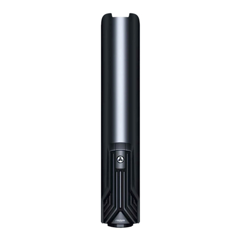
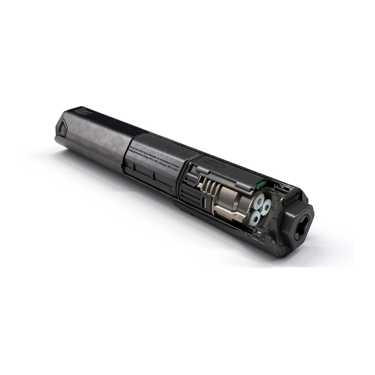
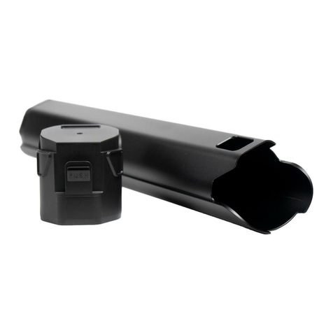
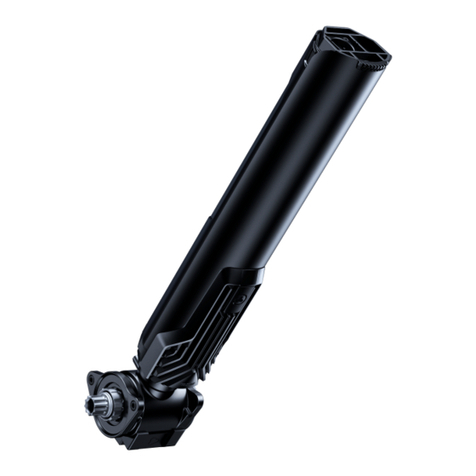
FAZUA RIDE 60 User manual

FAZUA RIDE 60 DRIVE SYSTEM
Assembly instructions
Edition 2022 | US 03.2023

© 2022 Porsche eBike Performance GmbH
All Rights Reserved

FUNDAMENTALS
1 ABOUT THESE INSTALLATION INSTRUCTIONS.............................................................................................4
2 GENERAL SAFETY INSTRUCTIONS..............................................................................................................5
INSTALLATION AND REMOVAL OF THE COMPONENTS
3 CONTROL ELEMENT AND DISPLAY .............................................................................................................6
3.1 Ring Control.................................................................................................................................................6
3.1.1 Mounting Ring Control .................................................................................................................................................... 6
3.1.2 Disassembling Ring Control............................................................................................................................................ 8
3.2 Road Control................................................................................................................................................9
3.2.1 Mounting Road Control ................................................................................................................................................... 9
3.2.2 Disassembling Road Control...........................................................................................................................................11
3.3 LED Hub...................................................................................................................................................... 12
3.3.1 Mounting LED Hub ..........................................................................................................................................................12
3.3.2 Dismantling LED Hub ......................................................................................................................................................14
3.4 Control Hub................................................................................................................................................ 16
3.4.1 Mounting Control Hub ....................................................................................................................................................16
3.4.2 Disassembling Control Hub............................................................................................................................................18
4 CHARGE PORT ........................................................................................................................................ 19
4.1 Mounting the charge port........................................................................................................................ 19
4.2 Disassembling the charge port ...............................................................................................................20
5 DRIVE UNIT .............................................................................................................................................21
5.1 Installing the drive unit............................................................................................................................ 21
5.2 Removing the drive unit...........................................................................................................................25
6 RACK 430 ..............................................................................................................................................28
6.1 Installing the rack.....................................................................................................................................28
6.2 Removing the rack ...................................................................................................................................32
7 ENERGY..................................................................................................................................................34
7.1 ENERGY 430 .............................................................................................................................................. 34
7.1.1 Using ENERGY 430 ......................................................................................................................................................... 34
7.1.2 Removing ENERGY 430.................................................................................................................................................. 34
7.2 ENERGY 430 fix..........................................................................................................................................35
7.2.1 Installing ENERGY 430 fix.............................................................................................................................................. 35
7.2.2 Disassembling ENERGY 430 fix..................................................................................................................................... 37
ENGLISH|ASSEMBLY INSTRUCTIONS
4
1 ABOUT THESE INSTALLATION INSTRUCTIONS
These installation instructions are part of the FAZUA RIDE 60 drive system and are intended specifically for
FAZUA dealers, as well as trained technical and service personnel. These installation instructions describe
all necessary steps for installing the components of the drive system in the e-bike or for removing the
mounted components from the e-bike.
IMPORTANT: The installation instructions are expressly not designed for use by laypersons or as an alternative /
supplement to the original instructions.
To highlight risks and important additional information, these assembly instructions use the following markings:
WARNING
Risks that could result in death or serious injury are marked with the signal word "WARNING".
NOTE
Risks relating to assembly errors or damage to the product are marked with the signal word "NOTE".
Useful additional information is marked with this information symbol.
Information on the specific torques for bolted connections is marked with the torque wrench
symbol.

ASSEMBLY INSTRUCTIONS|ENGLISH
5
2 GENERAL SAFETY INSTRUCTIONS
WARNING
Risk of accidents and injuries if the safety information is not observed!
If you do not observe the general safety information listed here, you may be injured and the drive
system or individual components may be damaged. Improperly installed or damaged components
pose significant risks of accidents and injuries to the user of the e-bike.
►Never open the components of the drive system. Only Porsche eBike Performance GmbH
employees are permitted to open the components of the FAZUA RIDE 60 drive system. Unautho-
rized opening will invalidate the warranty claim and there is a risk of irreparable damage to the
drive system.
►Do not carry out any work on the drive system or the e-bike while the battery is being charged
via the charging port on the e-bike to avoid injury. Generally speaking: The e-bike must never be
connected to the mains via the charging connection during service work.
►ATTENTION! When the drive system is fully assembled, the cables for the rear brake and the rear
derailleur (and other cables if necessary) must always be routed first. The installation of the
drive system can be started subsequently. Keep to the following sequence when installing the
components:
1. Control element (Ring Control, Road Control or Control Hub),
2. Display (LED Hub; not applicable when using Control Hub),
3. Charge port,
4. Permanently installed battery (only when using ENERGY 430 fix; not applicable when using
ENERGY 430),
5. Drive unit,
6. Rack (only when using ENERGY 430; not applicable when using ENERGY 430 fix),
7. Removable battery (only when using ENERGY 430; not applicable when using ENERGY 430 fix).
►When replacing components mounted on the drive unit and all other components of the e-bike
(e.g. chainring, pedals), only identical components or components approved by the bike manu-
facturer may be mounted.
►Clean and degrease all threads before screwing.
►Allow the threadlocker to harden for at least 6 hours after installation.
►When using threadlockers, we recommend the use of Loctite 243.
►Observe the instructions for the individual steps precisely to avoid assembly errors and damage
to the components.

ENGLISH|ASSEMBLY INSTRUCTIONS
6
3 CONTROL ELEMENT AND DISPLAY
Depending on the individual configuration of the drive system/ the composition of the drive
components, operating elements and display are either:
• Two separate components (operating parts: Ring Control or Road Control, display: LED Hub).
Or
• A combined component (Control Hub).
3.1 Ring Control
Component parts:
• Ring Control with cable
Connecting elements supplied:
• 1 M3×10 screw
Tools needed:
• T10 Torx screwdriver
3.1.1 Mounting Ring Control
NOTE
►Make sure that the cable is not kinked or under tension.
►Make sure that the cable is not damaged at sharp-edged frame openings/ bushings.
►Make sure that the cable is laid according to the manufacturer's specifications (cable routing, etc.).
Depending on the bike in which the drive system is installed, different cable guides are
provided (standard cable guide, integrated cable guide, etc.).
The following installation description shows the standard cable routing, where the cable is
routed from the handlebar through a side opening into the bike frame. With a (fully) integrated
cable routing you lay the cables if necessary, if stem and handlebars are not yet mounted.
In this case, perform Step 2 "Laying cable" first and then step 1.
Contact the bike manufacturer if you have any questions about the intended cable routing.
Step 1: Attaching Ring Control to the handlebars
→
Slide Ring Control onto the handlebars from
the outside (preferably on the left side of the
handlebar).

ASSEMBLY INSTRUCTIONS|ENGLISH
7
→
When positioning Ring Control, make sure that
there is a distance of at least 4 mm to all other
components on the handlebar (including the
handlebar grip, brake lever).
4 mm 4 mm
→
Fix the ring control in the correct position on the
handlebars.
To do so, tighten the screw (1) on the clamp with
the T10 Torx screwdriver.
0.5 Nm
IMPORTANT: Tighten the screw (1) only so far that
the ring control no longer twists during opera-
tion. The torque achieved may then be below the
maximum permissible torque.
1
Step 2: Laying cable
→
Guide the cable of Ring Control from the outside
through the corresponding opening in the e-bike
frame.
Lead the cable end with the socket (2) out to the
opening for LED Hub in the top tube.
IMPORTANT: The openings in the frame are some-
times very sharp-edged and can permanently
damage the cable.
2
→
Continue with the connection of Ring Control to LED Hub and the assembly of LED Hub (see chapter 3.3.1
"Mounting LED Hub").

ENGLISH|ASSEMBLY INSTRUCTIONS
8
3.1.2 Disassembling Ring Control
IMPORTANT: To disassemble the ring control, you must first disassemble LED Hub and disconnect the ring
control from LED Hub (see chapter 3.3.2 "Dismantling LED Hub").
Step 1: Pulling the cable out of the e-bike frame
→
Pull the cable of the ring control out of the e-bike
frame.
IMPORTANT: Be careful to pull out the cable care-
fully so that the cable and the socket (2) are not
damaged.
2
Step 2: Removing Ring Control from handlebar
→
Loosen the fixation of Ring Control on the handle-
bars.
To do so, loosen the screw (1) on the clamp by a
few turns using the T10 Torx screwdriver.
1
→
Remove Ring Control outward from the handle-
bars.

ASSEMBLY INSTRUCTIONS|ENGLISH
9
3.2 Road Control
Component parts:
• Road Control with cable
for mounting on right (RoC R)
• Road Control with cable
for mounting on left (RoC L)
• RoC splitter
Road Control consists of two switches: RoC R and RoC L. The two switches have different
functions and bear markings indicating on which side of the handlebar it should be mounted
with priority.
Side-inverted mounting of the two switches should only be carried out at the explicit request
of the customer.
3.2.1 Mounting Road Control
NOTE
►Make sure that the cables are not bent or installed under tension.
►Make sure that the two switches (RoC R and RoC L) are mounted on the correct side.
►Make sure that the cables are not damaged at sharp-edged frame openings/ bushings.
►Make sure that the cables are laid according to the manufacturer's specifications (cable routing, etc.).
Depending on the bike in which the drive system is installed, different cable guides are
provided (standard cable guide, integrated cable guide, etc.).
The following installation description shows the standard cable routing, where the cables
are routed from the handlebars through a side opening into the bike frame. With a (fully)
integrated cable routing you lay the cables if necessary, if stem and handlebars are not yet
mounted. In this case, perform Step 2 "Laying cable" first and then step 1.
Contact the bike manufacturer if you have any questions about the intended cable routing.

ENGLISH|ASSEMBLY INSTRUCTIONS
10
Step 1: Mounting Road Control on the handlebars
→
If necessary, mount the stem and handlebars on the e-bike.
→
Mount the two switches (RoC R and RoC L) on the
handlebars.
To do so, first stick the respective switch to the
desired position on the handlebars with adhesive
tape.
Then wrap the switch with grip tape (8) as shown
to additionally fix it.
IMPORTANT: For both switches, make sure to
mount them on the correct side (see markings on
the cables). RoC R must be mounted on the right
handlebar side, RoC L on the left handlebar side.
8
Step 2: Laying cable
→
Guide the cables of the two switches (RoC R
and RoC L) from the outside through the corre-
sponding opening in the e-bike frame.
Lead the cable ends with the plug (3) or the
socket (4) out to the opening for LED Hub in the
top tube.
IMPORTANT: The openings in the frame are some-
times very sharp-edged and can permanently
damage the cables.
3
4
→
Connect the two cables (RoC R and RoC L) to the
RoC splitter.
To do so, plug the connector (3) on the cable of
the right switch (RoC R) into the socket (5) on the
cable of the RoC splitter and the connector (6) on
the cable of the RoC splitter into the socket (4)
on the cable of the left switch (RoC L). The free
socket (7) is later used to connect to the LED hub.
3
4 6
5 7
→
Lay the excess of the two cables (RoC R and RoC L) to a loop.
Depending on the mounting position, the required cable length will vary.
→
Continue with the connection of Road Control to LED Hub and the assembly of LED Hub (see chapter 3.3.1
"Mounting LED Hub").

ASSEMBLY INSTRUCTIONS|ENGLISH
11
3.2.2 Disassembling Road Control
IMPORTANT: To disassemble Road Control, you must first disassemble LED Hub and disconnect Road Control
from LED Hub (see chapter 3.3.2 "Dismantling LED Hub").
Step 1: Pulling the cable out of the e-bike frame
→
If necessary, remove the stem and handlebars from the e-bike to be able to pull the cables out of the
e-bike frame (integrated cable routing).
→
Disconnect Road Control (RoC R and RoC L) from
the RoC splitter.
To do so , pull the plug (3) on the cable of the right
switch (RoC R) out of the socket (5) on the cable
of the RoC splitter and the plug (6) on the cable of
the RoC splitter out of the socket (4) on the cable
of the left switch (RoC L).
IMPORTANT: Do not pull on the cables, but grasp
the plug and socket to avoid damaging the cables.
3
4 6
5
→
Pull the cables of the two switches (RoC R and
RoC L) out of the e-bike frame.
IMPORTANT: Take care to pull out the cables
carefully so that the cables and the plug (3) or
socket (4) are not damaged.
3
4
Step 2: Removing Road Control from the handlebars
→
Detach the two switches (RoC R and RoC L) from
the handlebars.
To do so, unwind the grip tape (8) at the respec-
tive switch.
→
Then remove the two switches (RoC R and RoC L)
from the handlebars.
8

ENGLISH|ASSEMBLY INSTRUCTIONS
12
3.3 LED Hub
Component parts:
• LED Hub with two cables
• Frame unit of LED Hub
Connecting elements supplied:
• 1 M3×22 screw (frame unit)
Tools needed:
• T10 Torx screwdriver
3.3.1 Mounting LED Hub
NOTE
►Make sure that the cable is not kinked or under tension.
►Make sure that the cable is not damaged at sharp-edged frame openings/ bushings.
►Make sure that the cable is laid according to the manufacturer's specifications (cable routing, etc.).
Step 1: Connecting the control element to LED Hub
→
Guide the two cables of LED Hub with the connec-
tors (9) and (10) from above through the frame
unit of LED Hub.
IMPORTANT: Do not insert LED Hub into its frame
unit yet!
→
Connect the control element (Ring Control /
Road Control) to LED Hub.
To do so, plug the connector (9) on the cable of
LED Hub into the socket (2) or (7) on the cable of
Ring Control/ the RoC splitter. The free plug (10)
is later used for connection to the drive unit.
IMPORTANT: Make sure that the plug (9) is
inserted correctly. The yellow marking on the
plug (9) must disappear completely into the
socket.
2 / 7
910

ASSEMBLY INSTRUCTIONS|ENGLISH
13
Step 2: Laying cable
→
Guide the cable of LED Hub through the opening
for LED Hub and inside the e-bike frame to the
down tube.
The cable end with the plug (10) hangs freely in
the opening for the ENERGY in the down tube.
→
Put the cable surplus of LED Hub and the
connected control element (Ring Control /
Road Control + RoC splitter) together to a loop.
→
Push the loop through the opening for LED Hub
into the top tube so that the cables are not bent
and do not hinder the insertion / removal of
LED Hub.
IMPORTANT: For pressure relief from below, the
loop in the top tube must run at least 5 cm behind
the opening for LED Hub.
10
5 cm
Step 3: Attaching the frame unit to the e-bike
→
Insert the frame unit of LED Hub into the opening
provided in the top tube.
To do so, first hook the hooks (11) at the lower
end of the frame unit and then press the upper
part of the frame unit into the opening.
1
2
11
→
Fix the frame unit to the top tube.
To do so, screw the screw (12) into the attach-
ment point of the frame unit using the T10 Torx
screwdriver.
IMPORTANT: Make sure that frame unit is seated
in the opening without play.
0.5 Nm
12

ENGLISH|ASSEMBLY INSTRUCTIONS
14
Step 4:Inserting LED Hub into the frame unit
→
Insert LED Hub into its frame unit.
To do so, first push the rear end of LED Hub into
the frame unit and then push the front end of
LED Hub down (into the frame unit).
The correctly inserted LED Hub engages in the
frame unit with an audible click.
"Click"
2
1
3.3.2 Dismantling LED Hub
IMPORTANT: In order to completely disassemble LED Hub, you must first disconnect LED Hub from the drive
unit (see Step 1 "Disconnecting components from the drive unit" in chapter 5.2 "Removing the drive unit").
Step 1: Removing LED Hub from the frame unit
→
Click LED Hub out of its frame unit.
To do so, lift LED Hub at the front end to the
maximum and then carefully push LED Hub
forwards / upwards out of the frame unit.
1
2

ASSEMBLY INSTRUCTIONS|ENGLISH
15
Step 2: Removing the frame unit from the e-bike frame
→
Loosen the screw connection of the frame unit.
To do so, unscrew the screw (12) from the frame
unit using the T10 Torx screwdriver.
12
→
Remove the frame unit of the LED Hub from the
opening in the top tube.
To do so, first lift the upper end of the frame unit
and then loosen the hooks (11) on the lower part
of the frame unit.
1
2
11
Step 3: Disconnecting the control unit from LED Hub
→
Disconnect the connected control unit from
LED Hub.
To do so, pull the plug (9) on the cable of LED Hub
out of the socket (2) or (7) on the cable of
Ring Control / the RoC splitter.
IMPORTANT: Do not pull on the cables, but grasp
the plug and socket to avoid damaging the cables.
2 / 7
9

ENGLISH|ASSEMBLY INSTRUCTIONS
16
3.4 Control Hub
Component parts:
• Control Hub with cable
Connecting elements supplied:
• 1 M3×10 screw
Tools needed:
• T10 Torx screwdriver
NOTE
►Make sure that the cable is not kinked or under tension.
►Make sure that the cable is not damaged at sharp-edged frame openings/ bushings.
►Make sure that the cable is laid according to the manufacturer's specifications (cable routing, etc.).
Depending on the bike in which the drive system is installed, different cable guides are
provided (standard cable guide, integrated cable guide, etc.).
The following installation description shows the standard cable routing, where the cable is
routed from the handlebar through a side opening into the bike frame. With a (fully) inte-
grated cable routing you lay the cables if necessary, if stem and handlebars are not yet
mounted. In this case, perform Step 2 "Laying cable" first and then step 1.
Contact the bike manufacturer if you have any questions about the intended cable routing.
3.4.1 Mounting Control Hub
Step 1: Attaching Control Hub to the handlebars
→
Slide Control Hub onto the handlebars from the
outside (preferably on the left side of the handle-
bars).
Make sure that Control Hub has a minimum
distance of 4 mm to other components or
controls on the handlebars.

ASSEMBLY INSTRUCTIONS|ENGLISH
17
→
When positioning Control Hub, make sure that
there is a distance of at least 4 mm to all other
components on the handlebars (including the
handlebar grip, brake lever).
4 mm 4 mm
→
Fix Control Hub in the correct position on the
handlebars.
To do so, tighten the screw (13) on the clamp with
the T10 Torx screwdriver.
0.5 Nm
IMPORTANT: Tighten the screw (13) only so far
that Control Hub no longer twists during opera-
tion. The torque achieved may then be below the
maximum permissible torque.
13
Step 2: Laying cable
→
Guide Control Hub cable through the e-bike frame
to the down tube.
The cable end with the plug (14) hangs freely in
the opening for the ENERGY in the down tube.
IMPORTANT: The openings in the frame are some-
times very sharp-edged and can permanently
damage the cable.
14

ENGLISH|ASSEMBLY INSTRUCTIONS
18
3.4.2 Disassembling Control Hub
IMPORTANT: To be able to completely disassemble Control Hub, you must first disconnect Control Hub from
the drive unit (see Step 1 "Disconnecting components from the drive unit" in chapter 5.2 "Removing the
drive unit").
Step 1: Pulling the cable out of the e-bike frame
→
Pull the cable of Control Hub out of the e-bike
frame.
IMPORTANT: Be careful to pull out the cable care-
fully so that the cable and the socket (14) are not
damaged.
14
Step 2: Removing Control Hub from the handlebars
→
Release the fixation of Control Hub on the handle-
bars.
To do so, loosen the screw (13) on the clamp by a
few turns using the T10 Torx screwdriver.
13
→
Remove Control Hub from the handlebars towards
the outside.

ASSEMBLY INSTRUCTIONS|ENGLISH
19
4 CHARGE PORT
Component parts:
• Charge port with cable
• Charge cap
Connecting elements supplied:
• 4 screws*
Tools needed:
• Screwdriver*
* Screw type and size depend on the bike manufacturer.
The illustrations shown here for mounting / dismounting the charge port are exemplary,
the mounting position of the charge port depends on the bike manufacturer.
4.1 Mounting the charge port
NOTE
►Make sure that the cable is not kinked or under tension.
►Make sure that the cable is not damaged at sharp-edged frame openings/ bushings.
►Make sure that the cable is laid according to the manufacturer's specifications (cable routing, etc.).
Step 1: Inserting the charge port
→
First insert the charge cap into the opening
provided on the e-bike.
Make sure that the attachment points in the
charge cap and in the e-bike frame are on top of
each other.
→
Then insert the charge port into the open charge
cap with the socket (15) on the cable first.
15
Step 2: Fixing the charge port into place
→
Fix the charge port and charge cap to the e-bike
frame.
To do so, screw the screws (16) into the fastening
points with the screwdriver.
0.3 Nm
16

ENGLISH|ASSEMBLY INSTRUCTIONS
20
Step 3: Laying cable
→
Guide the cable of the charge port inside the
e-bike frame in the direction of the holder for the
drive unit.
The cable end with the socket (15) hangs freely in
the holder for the drive unit.
15
4.2 Disassembling the charge port
IMPORTANT: To completely disassemble the charge port, you must first disconnect the charge port from the
drive unit. To do so, you must remove the drive unit from the e-bike (see chapter 5.2 "Removing the drive
unit").
Step 1: Loosening the screw connection
→
Loosen the screw connection of the charge port.
To do so, unscrew the screws (16) completely
from the attachment points using the screw-
driver and remove them.
16
Step 2: Removing the charge port
→
Remove the charge port and the charge cap from
the opening on the e-bike.
IMPORTANT: Be careful to pull out the cable care-
fully so that the cable and the socket (15) are not
damaged.
15
Other manuals for RIDE 60
4
Table of contents
Other FAZUA Bicycle Accessories manuals

FAZUA
FAZUA Evation User manual

FAZUA
FAZUA Evation User manual

FAZUA
FAZUA RIDE 50 TRAIL User manual

FAZUA
FAZUA RIDE 5 0 TRAIL/STREET User manual

FAZUA
FAZUA RIDE 60 User manual

FAZUA
FAZUA RIDE 60 User manual

FAZUA
FAZUA Evation User manual

FAZUA
FAZUA RIDE 60 User manual

FAZUA
FAZUA RIDE 50 TRAIL/STREET User manual

FAZUA
FAZUA Evation User manual