Fein MSf 679 b User manual

To be handed to the workshop
Operating instructions
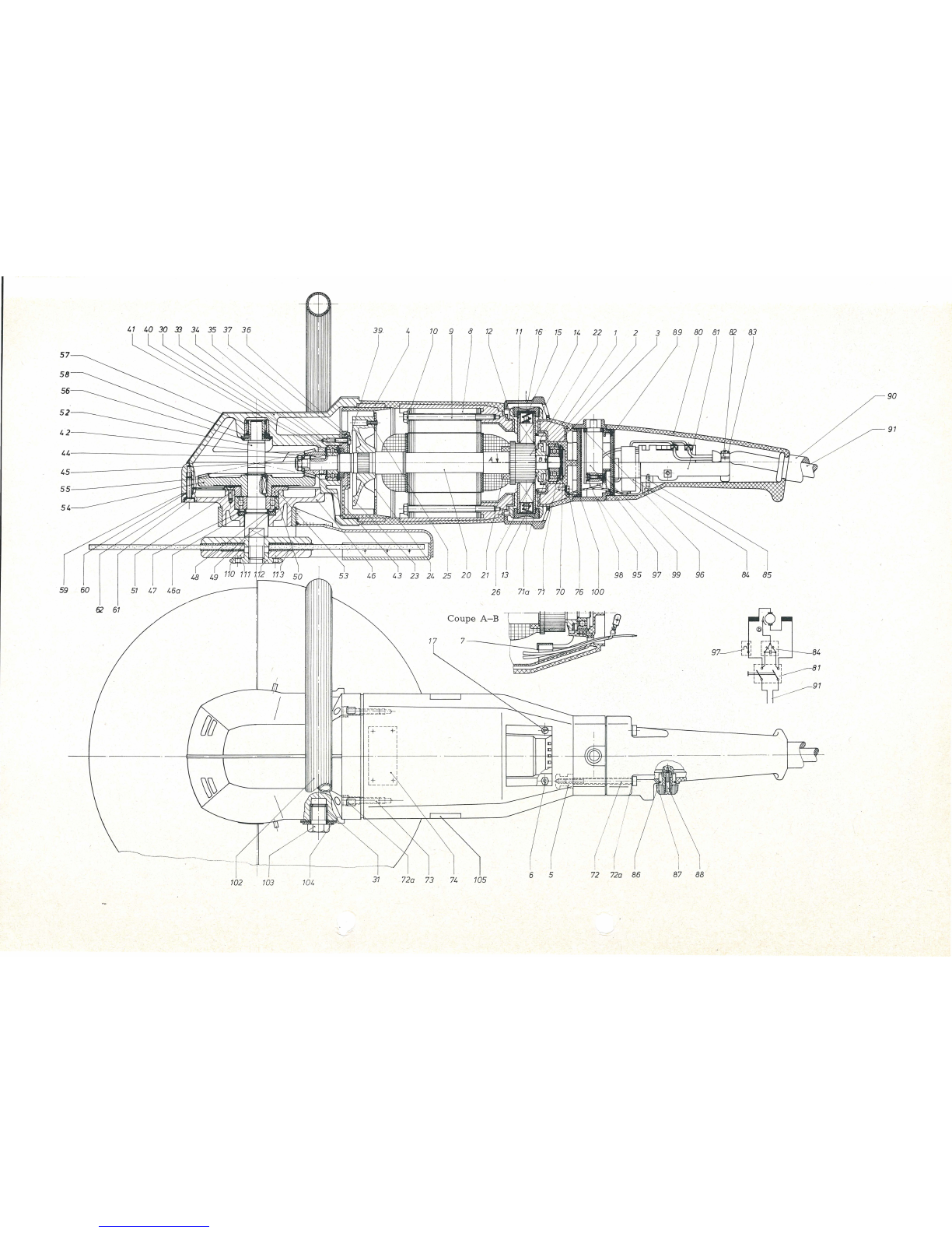
for the Angle Grinder type MSf
679
b
1.
Technical
Data
Type
of
current
:
"'
(AC
single
phase)
Fuses
for
220
V:
10 A
slow
or
15 A
fast
or
automatic
fuse
10 A
type
G.
'
Speed
Input
Output
Net
Weight
T
ype
R.P.M.
Watts
Watts
I
lbs
kg
MSf
679b
5100 2000 1400
16
7,2
I
2.
Construction
The
angle
grinder
MSf
679 b
is
an
electric
tool
of
Class
II
according
to
VDE
regulations
0740.
The
protective
insu
la
tion
·
is
additional
to
the
normal
insulation
and
protects
the
operator
against
electric
acciden
ts
caused
by
defective
normal
insulation.
The
protective
insulation
is
attained
by
the
motor
housing
made
of
polyamide-
shockproof
an
d
resistant
to
leakag
e
curren
ts
-
a
nd
by
in
sulating
the
armature
aga
i
nst
th
e
pinion
.
The
machine
is s
upplied
with
a
two-
core
cable
w
ithout
earth
wire
a
nd
must
not
be
earthed.
The
dustproof
switch
is
mounted
in
the
handle.
The
angle
grinder
is
equipped
with
a
protective
motor
switch.
When
overloaded,
it
disconnects
th
e
motor.
When
th
e
prot
ec
tiv
e
motor
switch
is
released,
it
can
again
be
con
n
ected
after
20
or
30
seconds.
Switch
must
be
in
the
"Off"
position,
before
connectin
g
again
the
protective
motor
switch.
The
machine
is
test
ed
with
the
prescribed
test
v
oltage
of
4000 V.
It
is
radio
suppressed
according
to
radio
interf
ere
nce
VD
E 0875.
Th
e
bevel
gear
hav
e he
li
ca
l
teeth.
Gears
are
l
apped
for
accura
te
meshing;
both
p
ar
ts
to
be
supplied
as
pairs
only
.
Gea
rs a
nd
bearings
ar
e
protected
aga
inst
dust
~
nd
l
oss
of
gre
ase
.
-
Th
e
slots
for
the
coo
l
ing
air
of
th
e
motor
are
lo
cated
in
th
e
gear
head.
They
allow
an
additional
cooling
of
the
gear
head.
BE
443/e
GW
5.
73
. P.rint
ed
in
German
y
max.
Thread
Grinding
wheel
periphera
l
speed
of
I
ma
x.
dia
I
ma
x. w
id
th I
bore
type
in.
I
mm
in.
I
mm
in.
i ft/s I m/s
spindle
mm
flexib
le
grinding
11
13j,6
300
.,32
4 7
Ia
22.2 262 80 M 14
wheel
To
p
reven
t
the
overbridg
i
ng
of
the
insul
a
tion
no
addition
al
markfng
plates
and
signs
mus
t
be
ri
vete
d
or
scre
wed
on
th
e
housing
. W e
recommend
the
u
se
of
transfers
only.
3.
Connection
and
operation
Main
voltage
must
correspon
d
to
the
opera
ti
ng
volt
age
marked
on
the
rating
plate.
Th
e
tool
ca
n
be
plugg
ed
into
pla
in
or
safet
y
sockets.
Switch
must
be
in
th
e
"Off"
po
s
iti
on
w
he
n
co
nn
ecting.
The
gr
i
nders
must
not
be
used
w
ithout
wh
eel
guards.
Do
not
exceed
the
dime
ns
ions
·
of
grinding
wheels
stipulated
.
For
cutting
off,
use
cutting
wheels
together
with
the
prescribed
flanges
and,
in
addition
to
this,
our
wheel
guard
with
adjustable
support
for
cutting
off
stone.
4.
Maintenance
and
lubrication.
The
ang
le
grinder
requires
ad
equate
maintena
nce.
Before
star
-
ting
any
maintenance
work
pull
plug
from
socket.
After
3-4
weeks
the
m
achi
ne,
in
particular
ca
r
bon
hold
e
rs
and
insula
te
d
par
ts
,
should
be
cleaned
of
carbon
dust
a
nd
dirt.
Th
is
is
done
by
m
ea
ns
of
a
brush
or
compressed
air.
Worn
ca
r
bon
brush
es
automatica
ll
y
switch
off
the
mach
in
e
utte
r
re
ach
ing
their
minimum
le
ngth
.
After
checkin
g
the
carbon
brushes
make
sure
to
refit
them
in
their
origina
l
position
and

90
91
84
r-
N'
--
'
~
·~
-
r=:
:
31
7
2a
73 74 105 5 72
72a
86
88
'--

Component Parts
0 I
z
Order
:::.
Description
....
0
....
Reference
""
0 I
z
Order
f
Description
....
....
Reference
a
""
'"" '""
1-17
MK
3-111-1 1) 1
motor
housing
assembled
for
80-89 1
GH4-67-1
1 I
handle
assembled
with
switch
136-260
v 80
GH4-67
1
handle
1-17
MK3-111-2
1) 1
motor
housing,
assembled
for
110-135
v
1
MK
3-111 1
motor
housing
7
PT
27-30 2
cover
8
state
type 1
pole
housing,
assembled
with
and
ten
sion
winding
9
SR
1-M5x80 2
hexagon
screw
10
PT
37-8 2
securing
plate
11
EZ 12-47-2 2
carbon
holder
assembled
with
wire
14
EZ 11-61 2
carbon
brush
15
EZ 13-9 2
carbon
holder
cap
16
PT
27-29 2
motor
housing
cover
17
SR
6k-M3x6
4
fillister
countersunk
screw
20-26
state
type 1
armature
with
winding,
commutator
and tens.ion
and
fan
FL 4-11-1 1
fan,
assembled
30-62
GH
6-76
-1
1 I
gear
housing,
assembled
30
GH
6-76 1
gear
housing
33 LK 16-38 1
grooved
ball
bearing
34
PT
11-58 1
cover
plate
35
DJ
1-50 1
felt
ring
36
JS
28-8 1 I
air
conductor
39
SR
2b-M4x15
3
cylindrical
screw
40
RJ
27i-12x28,1 1
Nilos
ring
41
RJ
24-29
washer
for
pinion
(as
needed)
81
EZ 1-61 1
switch
82
PT31-21
1
cable
clamping
bridge
83 SR3-M3,5x15 2
fillister
head
screw
84 EZ 22-36 1
capacitor
85
SR2-M3,5x10
2
cylindr
ic
al
screw
86
DJ
1-52 1
felt
ring
87
SA
5-47 1
sw
itc
h
lever
88
SR3-M3x15
1
fillister
head
screw
89
DJ
5-41 1
sealing
plate
90
JS
13-95 1
cable
protecting
sl
eeve
91
EZ 7-106 1
cable
95-
GH
7-79-1 1
housing
for
MSf
679
b/136
...
260 V
100
95-
GH7-79
-2 1
housing
for
MSf
679 b/
11
0
...
260 V
100
95
GH
7-79 1
housing
96
JS
26-9 1
rubber
plate
97 EZ 51-102-1 1
overload
protection
switch
for
MSf
679b/231
...
260
V
97 EZ 51-103-1 1
over
l
oad
protecti
on
switch
for
MSf
679 b/191
..
. 230 V
97 EZ 51-104-1 1
overload
protection
switch
for
MSf
679b/151 . . . 190 V
97 EZ 51-105-1 1
overload
protectio
n
switch
for
MSf
679 b/131 .
..
150 V
97 EZ
51
-106-1 1
overload
protection
switch
for
MSf
679b
/
111
.
..
130 V
42 BF 21-4x4x14 1
fitting
key
43 2) ZR 13-100 1 b
eve
l
pinion
97 EZ 51-107-1 1
overload
protection
switch
for
MSf
679b/110
V
44
PT
4-16 1
disc
45
MR
19-1 1
hexagon
nut
46
PT
19-66 1
bearing
plate
98 SR2-M2,6x15[ 1
cylindrical
screw
99
MR2
-M2,6 1
hexagon
nut
100
DJ
5-41 1
sealing
plate
46a
PT
11-62 1
cover
plate
102
MZ
20-26 1
bow
handle
47
DJ
1-49 1
felt
ring
103
SR
12-32 2
screw
48 RJ 27a-40x20,2 1
Nilos
ring
49 LK 16-25 1
grooved
ball
bearing
50
PT
16-36 1
end
cover
104
PT
5c-M14
I
2
disc
51
SR
5-M4x12
3
countersunk
screw
52
wB
·6-47 1
driving
shaft
53
BF
21-5x5x16 1
fitting
key
Accessories
542)
ZR
14-145 1
bevel
gear
55
RJ
29a-16x0,6 1
circlip
Seeger
M 10-153-1 1 w
heel
guard
56
RJ
19
-4 1
sealing
ri
ng
EZ 11-61 2
spare
carbon
brushes
57 I LK 6-24 1
needle
bearing
58
RJ
16-20 1
circlip
Seeger
Z
7-SW
17 L 1
single
end
spanner
z10-10 1
hexagon
socket
wrench
59
RJ
24-89
washer
for
bearing
plate
(as
needed)
' z 13-22 1
peg
spanner
60
DJ
12-6 1
ring
MZ60
-4
/FG9
1
tube
of
gear
grease
61
DJ
11
-5x9 4
sealing
r
ing
MZ60
-
5/FK5
1
tube
of
ball
bearing
grease
62
SR
33-M5x20 4
cylindrica
l
screw
70
FD5-7
2
spring
71
LK
16-22 1
grooved
ball
bearing
110-I
M7
-114-1 1 I
fl
a
nge
set
co
nsis
ting
of:
113
71a
RJ
28-10x1,2 1
circlip
Seeger
110 M 7-114 1
internal
flange
72
SR
33-M5x30 4
socket
head
cap
screw
111 M 8-111 1
outside
flange
72a
PT
5d-M5
8
securing
plate
(for
pos.
72
and
73) 112 M 8-52 1
threaded
flange
73
SR33-M5x30
4
socket
head
cap
screw
113
JS
16-51 2
rubber
gasket
76
SR2-M4x5
1
cylindrical
screw
MZ
38-
59
1
tool
carry
ing
case
1)
When
ordering,
state
type
and
tension.
2)
Parts
43
and
54
are
lapped
together
and
can
be
supplied
in
pairs
only.

check
that
they
move
easily
in
their
holder.
After
fitting
new
brushes,
run
tool
unloaded
for
about
15
minutes
to
allow
brushes
to
bed
in.
Please,
only
use
original
Fein
carbon
brushes
(order
reference:
EZ 11-61).
In
order
to
prevent
accidents,
check
cable
at
regular
intervals.
To
replace
the
cable,
take
off
screw
(88)
and
switch
lever
(87).
Unscrew
the
handle
(80)
off
the
motor
housing
(screws
72)
and
draw
it
backwards.
Loosen
cable
clamping
bridge
(82),
clamp
off
the
cable
from
the
switch
(81)
and
draw
it
out.
Every
900
duty
hours
the
machine
should
be
thoroughly
cleaned.
The
gearing,
working
under
high
load,
needs
particularly
good
lubrication.
We
recommend
to
renew
the
gear
grease
after
approx.
300
duty
hours.
Please,
only
use
our
special
Fein
gear
grease
FG
9.
A
mixing
of
this
grease
with
other
greases
endan-
gers
the
greasing
capacities,
and
therefore
also
use
FG 9
for
the
anti-friction
bearings
in
the
gear
head.
In
ord
er
to
check
and
renew
the
gear
grease
loosen
the
screws
(62)
and
remove
bearing
plate
(46)
with
driving
shaft
(52).
When
removing
the
bearing
plate
and
in
particular
when
re
-
assembling,
please,
don't
lose
packing
rings
(59)
and
sealing
ring
(60)
.
The
packing
rings
are
needed
for
adjustment
of
the
gearing;
their
loss
may
lead
to
damage.
For
good
and
adequate
lubrication
and
in
order
to
avoid
over-
heating
it
is
important
to
pack
the
gearing
with
the
grades
and
quantities
of
grease
listed
in
the
table
below.
Quantity
Contents
Type
of
Order
I
Reference
approx.
grease
I
oz
g oz g
For
gears
FG9
I 5 I 140 I
MZ
60-4/FG 9 I 6 I 180
i
' For
ball
bearings
FK5
MZ
60-5/FK 5 '/6 5
for
ball
approx.
1
13
bearing
part
71
of the
FG9
space
be-
MZ
60-3/FK 9
tween inner 3 90
for
roller
and
outer
bearings ring
parts
33
, I
49,
57
Larger
quantities
of
grease
are
packed
in
tins
.
No
claims
can
be
entertained
for
damage
due
to
negligent
main-
tenance
and
inadequate
lubrication
.
After
900
duty
hours
rinse
ball
bearings
in
clean
solvent
and
pack
with
fresh
grease
as
per
table
below.
The
space
between
inner
and
outer
ring
is
to
be
one
third
filled
with
grease
in
order
to
prevent
overheating
of
the
bearings.
5.
Dismantling
The
tool
should
only
be
taken
apart
by
an
expert
working
in
the
following
sequence:
1.
Remove
grinding
wheel
and
wheel
guard.
2.
Remove
motor
housing
cover
(16),
unscrew
carbon
holder
caps
(15)
and
take
out
carbon
brushes
(14).
3.
Remove
screws
(62)
and
draw
off
bearing
plate
(46)
with
driving
shaft
(52)
and
bevel
gear
wheel
(54).
Don't
lose
packing
rings
(59)
with
sealing
(60)!
4.
Loosen
screws
(73)
and
draw
gear
housing
(30)
with
armature
(20)
out
of
motor
housing
(1).
5.
Unscrew
hexagon
nut
(45)
off
armature
shaft
(20)
and
take
out
washer
(44),
bevel
pinion
(43),
fitting
key
(42),
washer
(41)
and
Nilos
ring
(40)
.
Then
draw
armature
shaft
(20)
out
of
gear
housing
(30).
6.
Loosen
screws
(39)
and
take
air
conductor
(36),
felt
ring
(35),
cover
plate
(34)
and
ball
bearing
(33)
out
of
gear
housing
(30).
7.
Remove
needle
bearing
ring
with
sealing
ring
(56)
from
driv-
ing
shaft
(52).
Remove
circlip
Seeger
(55),
bevel
gear
wheel
(54)
and
fitting
key
(53).
Unscrew
screws
(51),
remove
flange
(50)
and
draw
driving
shaft
(52)
with
ball
bearing
(49)
out
of
bearing
plate
(46).
8.
Loosen
screw
(88)
and
remove
switch
lever
(87).
Remove
screws
(72)
and
push
handle
(80)
backwards.
Clamp
off
cable
and
capacitor
(84)
from
motor
housing
(1)
and
remove
switch
(81)
.
Re-assemble
in
reverse
sequence.
When
refitting
pm10n
and
bearing
plate,
please,
bear
in
mind
that
washers
(41, 59)
are
to
be
placed
in
their
right
places
as
they
are
needed
for
accurate
adjustment
of
the
gearing.
When
fitting
bearing
plate
check
that
bevel
gear
wheels
mesh
accurately
.
For
this
purpose
turn
driving
shaft
(52)
slightly;
only
then
fasten
screws
(62).
6.
Repair and Spare Parts
We
recommend
our
FEIN
Service
Stations
to
carry
out
all
over-
haul
and
repair
work
quickly
and
expertly.
We
deliver
special
tools
to
carry
out
repairs
.
The
base
tube
ZSO
8-8
and
the
two-part
base
plate
ZSO
9-57
are
used
to
take
off
the
bevel
gear
(54).
The
tube
ZSO
8-1,
the
base
ZSO
28-2,
the
support
ZSO
34-3
and
the
dismantling
device
ZSO
28-5-1
will
be
used
to
take
off
the
pole
housing.
The
spanner
ZSO
77-7-1
is
used
for
disassembling
the
carbon
holders
and
the
spanner
ZSO
71
-6
for
assembling.
When
ordering
spare
parts,
please,
quote
Type
and
Serial
No.
of
the
machine as
well
as
Order
Reference
of
the
required
part
or
send
in
the
damaged
part.
We
draw
your
attention
to
the
need
to
carry
out
a
high
voltage
test
in
accordance
with
your
local
regulations
(or
VDE
regula-
tion
0740)
before
taking
a
tool
into
service
after
any
repair
carried
out
by
your
own
staff.
(
Other Fein Grinder manuals

Fein
Fein WSG 12-70E Quick start guide

Fein
Fein 7 221 73 User manual

Fein
Fein CCG18-115BLPD-SEC Series User manual

Fein
Fein Grit GIXS Series User manual

Fein
Fein MB 106-1 User manual

Fein
Fein GRIT GIMS150 User manual

Fein
Fein GRIT GHB 15-50 Setup guide

Fein
Fein WSg 20-180 User manual

Fein
Fein GRIT GI100 User manual

Fein
Fein GRIT GXC Series User manual

Fein
Fein MSho852-1ZV User manual

Fein
Fein GRIT GIR User manual

Fein
Fein MSfv 649 User manual

Fein
Fein WSG 15-125PSQ User manual

Fein
Fein CG10-125 Series User manual

Fein
Fein MSh 636-1 Quick start guide

Fein
Fein MShyo869-1d User manual

Fein
Fein MShy649-1 User manual

Fein
Fein CCG18-115 BL User manual

Fein
Fein GRIT GHB 15-50 User manual