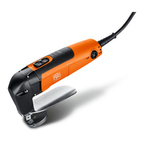
Fein 7 232 32/BLK 1.6 Setup guide

1 88 50 307 06 9 X 04.03 1
1 88 50 307 06 9 X 04.03 Printed in Germany - Imprimé en Allemagne, FEIN Stuttgart
7 232 32/BLK 1.6
Reparaturanleitung
Repair Instructions
Instructions de réparation
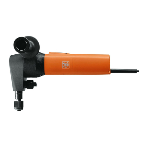
Elektro-Knabber
Electric Nibbler
Grignoteuse électrique
Technische Änderungen vorbehalten/Subject to technical modifications/Caractéristiques techniques sous réserve de modifications.

21 88 50 307 06 9 X 04.03
D7 232 32/BLK 1.6
Je nach Einsatzart und Einsatzdauer, spätestens jedoch
nach 6 Monaten:
2.1.4 Maschine gründlich reinigen. Kugellager und Getriebe
mit Reinigungsmittel auswaschen und mit neuem Fett
versorgen (siehe Seite 4).
Achtung: Elektrische Teile nur trocken reinigen!
Schäden, die durch unsachgemäße Behandlung, Überlastung
oder normale Abnutzung entstanden sind, bleiben von der
Garantie ausgeschlossen.
Für Schäden, die durch Material- oder Herstellfehler entstan-
den sind, übernehmen wir die Gewährleistung.
2.2 Kohlebürstenwechsel
Die Kohlebürsten sind durch neue zu ersetzen, wenn sie
sich bis auf 7 mm Länge abgenützt haben. Beim Nach-
prüfen der Kohlebürsten muss darauf geachtet werden,
dass sie wieder in gleicher Stellung eingesetzt werden
und sich im Bürstenhalter leicht bewegen lassen.
Nur Original FEIN Kohlebürsten verwenden!
Neue Kohlebürsten zuerst 15 Minuten unbelastet ein-
laufen lassen.
2.3 Auswechseln der Netzanschlussleitung
Schrauben (160,170) entfernen. Deckel (150) abneh-
men. Schrauben (140) und Kabelklemmstück (130)
entfernen. Netzanschlussleitung aus den Anschlussklem-
men lösen. Neue Netzanschlussleitung in umgekehrter
Reihenfolge montieren.
3. Demontage der Maschine
3.1 Netzstecker ziehen!
3.2 Demontage Motor
3.2.1 Schrauben (160,170) lösen und den Deckel (150) ab-
nehmen.
3.2.2 Kohlebürsten (80) entnehmen. Schrauben (90) lösen
und Bürstenhalter (70) mit Steckverteiler (75) ent-
nehmen.
3.2.3 Schrauben (330) lösen und zus.ges. Knabberkopf mit
Zwischenlager (400) und montiertem Anker (250)
aus Motorgehäuse (10) entnehmen.
3.2.4 Zus.ges. Knabberkopf von Zwischenlager (400) ab-
nehmen. Dabei auf Scheibe (460) achten.
3.2.5 Anker (250) aus Zwischenlager (400) pressen.
Dabei auf Schutzgitter (320) achten.
3.2.6 Schalter (100) lösen und entnehmen.
3.2.7 Luftleitring (60) und Schrauben (50) entfernen und
Polpaket (40) entnehmen.
1. Technische Daten
Bestellnummer 7 232 32
Bauart BLK 1.6
Nennaufnahme 350 W
Leistungsabgabe 210 W
Stromart 1 ~
Schneidgeschwindigkeit ca. 1,9 m/min
Hubzahl bei Nennlast 1500/min
Gewicht 1,8 kg
Schutzklasse II q
Max. Werkstoffdicke:
Stahl bis 400 N/mm21,6 mm
Stahl bis 600 N/mm21,0 mm
Stahl bis 800 N/mm20,7 mm
Aluminium bis 250 N/mm22,5 mm
Bohrung zum Eintauchen Ø 22 mm
Schneidspurbreite 5 mm
Radius kleinste Kurve innen 30 mm
Radius kleinste Kurve außen 35 mm
2. Wartung
Bitte beachten Sie, dass Elektrowerkzeuge grundsätzlich nur
durch Elektrofachkräfte repariert, gewartet und geprüft werden
dürfen, da durch unsachgemäße Reparaturen erhebliche Gefähr-
dungen für den Benutzer entstehen können (BGV A2).
Wiederholungsprüfungen sind nach DIN VDE 0702-1 durch-
zuführen. Nach Reparaturen sind die Vorschriften nach
DIN VDE 0701 Teil 1 / 9.00 zu beachten.
Nur Original FEIN-Ersatzteile verwenden!
Sicherheitshinweise 3 41 30 054 06 1 durchlesen!
Bei Inbetriebsetzung, beim Arbeiten und bei der Wartung der
Maschine sind die einschlägigen Unfallverhütungsvorschriften
der Berufsgenossenschaften zu beachten.
Für die bestimmungsgemäße Verwendung gilt das Gesetz über
technische Arbeitsmittel (Gerätesicherheitsgesetz).
2.1 Allgemeine Wartungsarbeiten:
●Anschlussleitung (180) auf Beschädigungen kontrol-
lieren!
●Motor mit trockener Druckluft ausblasen.
●Kohlebürsten überprüfen (siehe Abschnitt 2.2).
2.1.1 Wartungsintervalle:
Nach ca. 300 Betriebsstunden:
2.1.2 Maschine reinigen. Bürstenhalter und Isolierteile aus-
blasen oder auspinseln. Wälzlager nach Tabelle Seite 4
fetten.
2.1.3 Getriebefett erneuern. Bitte verwenden Sie nur FEIN
Spezialfett nach Tabelle Seite 4.

1 88 50 307 06 9 X 04.03 3
D7 232 32/BLK 1.6
3.3 Knabberkopf
3.3.1 Überwurfmutter (710) lösen, Matrizenträger (670),
Stempel (660) und O-Ring (720) abnehmen.
3.3.2 Stirnradwelle (440) mit Stirnrad (430) und Rillen-
kugellager (420) aus Zwischenlager (390) abziehen.
3.3.3 Sicherungsring (530) entfernen und Stirnrad (510)
abnehmen. Auf Passfeder (520) achten.
3.3.4 Sicherungsring (490) entfernen, Exzenterwelle (500)
mit aufgepressten Kugellagern (470) und Distanzhülse
(480) aus äußerem Lager (590) entnehmen.
3.3.5 Pleuel (640) und Rolle (630) mit Nadellager (650) aus
äußerem Lager (590) entnehmen.
3.3.6 Stößel (610) mit Stößel-Unterteil (620) aus
äußerem Lager (590) herausziehen.
4. Montage der Maschine
Der Zusammenbau erfolgt sinngemäß in umgekehrter
Reihenfolge.
4.1 Bei der Montage des äußeren Lagers (590) mit dem
Zwischenlager (390) ist unbedingt auf die Scheibe
(460) zu achten.
4.1.1 Zus.ges. äußeres Lager (590) und Zwischenlager (390)
mit Loctite Nr. 574 abdichten.
4.2 Motor
4.2.1 Bei der Montage des Polpaketes (40) muss die
Beschriftung zur Schaltstange hin montiert werden,
sonst ensteht Leistungsverlust.
5. Schneidwerkzeuge
5.1 Schneidrichtung einstellen (Abb. 1 und 2)
— Überwurfmutter (710) ca. 3 Umdrehungen lösen.
—Matrizenträger (670) nach unten ziehen.
—Matrizenträger in Schneidrichtung drehen und
nach oben in Nut einrasten.
—Überwurfmutter festziehen.
5.2 Stempel wechseln (Abb. 3)
—Überwurfmutter (710) lösen.
—Matrizenträger (670) abziehen.
—Stempel (660) wechseln.
—Matrizenträger (670) aufsetzen.
—Überwurfmutter (710) festziehen.
5.3 Matrize wechseln (Abb. 4)
Schraube (690) herausdrehen.
Matrize (680) herausdrücken und wechseln.
Schraube (690) festziehen.
0
45
90
135
180
225
270
315
4.1.
2. 3.
a
660
670
710
690
Abb. 1 Abb. 2
Abb. 3 Abb. 4
Stempel und Matrizen sind nicht nachschleifbar.
Bei erhöhter Vorschubkraft, Leerhübe oder über-
mäßiger Gratbildung sind die Schneidwerkzeuge
verschlissen.
Empfehlenswert ist, für einen optimalen Schnitt
Matrize und Stempel gemeinsam zu wechseln.
6. Profilset 160 (siehe Abb. Seite 5)
6.1 Abbauen des Profilsets von der Maschine.
6.1.1 Überwurfmutter (10) lösen und komplettes Profilset
abnehmen.
6.2 Demontieren des Profilsets.
6.2.1 Verlängerung (30) mit Stempel (40) herausnehmen.
6.2.2 Matrize (90) und Stempelführung (80) nach Lösen der
Linsenschraube (70) abnehmen und Verschleißplatte
(100) entfernen.
6.3 Schneidwerkzeug erneuern und Profilset montieren.
6.3.1 Neue Matrize, Verschleißplatte und neuen Stempel
einsetzen und dabei beachten, dass Matrize (90) so
nach dem Stempel (40) ausgerichtet wird, dass der
Luftspalt zwischen Stempel und Matrize (90) auf
beiden Seiten gleich ist.
Achtung: Stempelführung (80) und Matrize (90)
nicht vertauschen. Einbaulage des
Stempels (40) beachten.
6.3.2 Weitere Montage in umgekehrter Reihenfolge zu 6.2.
6.4 Anbauen des Profilsets an die Maschine
6.4.1 Montage in umgekehrter Reihenfolge zu 6.1.
Beachten, dass die Verlängerung (30) im Stösselunter-
teil (620) eingehängt wird.
6.5 Abschließende Prüfung nach Punkt 2.

41 88 50 307 06 9 X 04.03
Schaltschema
Connecting plan
Schéma des connexions
Fettmengen und Fettarten
Types and quantities of grease
Types et quantités de graisse
UKW-Drossel nur von 121…250 V
inductor only 121…250 V
bobine de réactance seulement de 121…250 V
Fettart
Type of grease
Type de graisse
0 40 108 0400 8
0 40 119 0500 7
Tuben-Inhalt
Contents of tube
Contenu de tube
85 g
85 g
Bestellnummer
Order Reference
Référence
3 21 60 003 08 3
3 21 60 003 19 8
Fettmenge
Quantity
Quantité
Für Getriebe:/for gears:/pour engrenages: 15 g
Nadellager (450, 650) und Kugellager (420)
Needle bearing (450, 650) and ball bearing (420)
Roulement à aiguilles (450, 650) et roulement à billes (420)
ungefähr 1/3 des Raumes zwischen Innen- und Außenring
approx. 1/3 of the space between inner and outer ring
environ 1/3 du volume entre bague intérieure et extérieure
Gleitflächen von Stößel (610,620) und Pleuel (640) sowie
Stempel (660) einstreichen
Lubricate the sliding surfaces of the plunger (610, 620), connecting rod
(640) and also the punch (660)
Enduire les surfaces de glissage du coulisseau (610, 620) et de la bielle
(640) ainsi que le poinçon (660)
Netz
Net
Réseau
entfällt bei 60 Hz 120 V
not for 60 Hz 120 V
pas pour 60 Hz 120 V
7 232 32/BLK 1.6

1 88 50 307 06 9 X 04.03 5
7 232 32/BLK 1.6
Einzelteile Component Parts Pièces détachées
Teil-Nr. Bestellnummer
Part.No. Order Reference Benennung Description Désignation
No. Référence
25 3 01 09 152 02 0 1 zus. ges. Halter holder ass. ens. support
30 3 01 09 153 01 8 1 zus.ges. Verlängerung extension, ass. ens. prolongement
40 6 36 02 049 00 8 1 Stempel punch poinçon
65 6 36 02 049 01 7 1 Set (Profil-Set) set (profile extension set) set (set de prolongement)
70 3 13 09 123 00 9 4 Linsenschraube oval head screw vis à tête bombée
80 3 13 09 120 00 3 1 Stempelführung punch guide guidage de poinçon
90 3 13 09 122 00 5 1 Matrize die matrice
100 3 13 09 121 00 2 1 Verschleißplatte wearing plate plaque d'usure
6 29 07 036 00 9 1 Stiftschlüssel (Torx 20) socket head wrench (Torx 20) clé pour vis à six pans creux (Torx 20)
6. Profilset 160 / profile extension set 160 / Set de prolongement 160
9 26 02 071 01 9
Fettmengen und Fettarten
Types and quantities of grease
Types et quantités de graisse
Fettart
Type of grease
Type de graisse
0 40 119 0500 7
Tuben-Inhalt
Contents of tube
Contenu de tube
85 g
Bestellnummer
Order Reference
Référence
3 21 60 003 19 8
Fettmenge
Quantity
Quantité
Gleitflächen von Verlängerung (30) und Stempel (40) im
zus.ges. Halter (25) einstreichen (ca. 1 gr.)
Lubricate the sliding surfaces of the extension (30) and punch (40) in the
holder assembly (25) (approx. 1g)
Enduire les surfaces de glissage du prolongement (30) et du poinçon
(40) dans l'ens. support (25) (env. 1 g)

61 88 50 307 06 9 X 04.03
7 232 32/BLK 1.6

1 88 50 307 06 9 X 04.03 7
7 232 32/BLK 1.6
mit Loctite Nr. 574 abgedichtet
closed with "Loctite No. 574"
rendu étanche avec «Loctite No. 574»
M = 10 Nm
M = 15 Nm
Bei der Montage des Polpaketes muss die gestempelte
Fläche auf der Schaltstangenseite liegen
When assembling the pole housing make sure that
the marking points to the switch rod
Lors du montage veiller à ce que le marquage du
stator bobiné soit orienté vers la bielle

81 88 50 307 06 9 X 04.03
7 232 32 BLK 1.6
40
50
60
300
250
300
310
610
620
660
665
720
330
690
680
700
710
670
400
390
410
430
440
460
450
590
600
420
320
530
510
490
470
500
490
630
640
650
520
480
470
7 232 32/BLK 1.6
Bei der Montage des Polpaketes muss die gestempelte
Fläche auf der Schaltstangenseite liegen
When assembling the pole housing make sure that
the marking points to the switch rod
Lors du montage veiller à ce que le marquage du
stator bobiné soit orienté vers la bielle
●mit Loctite Nr. 574 abgedichtet
closed with "Loctite No. 574"
rendu étanche avec «Loctite No. 574»
●

1 88 50 307 06 9 X 04.03 9
120
30
20
10
75
70
90
80
190
180
130
140
150
160
170
100
N 24/ GB
182
185
N 09/ CA N 08/ CH
184
Anzahl
Quantity
Quantité
7 232 32/BLK 1.6
Teil-Nr. Bestellnummer
Part.No. Order Reference
No. Référence
10 3 19 01 109 01 8 1
20 3 28 16 051 00 1 1
30 3 28 05 152 00 9 1
40 5 1 272 004 11 9 (110-120 V) 1
5 1 272 004 23 5 (230-240 V) 1
50 4 30 70 014 00 0 2
60 3 14 28 114 00 8 1
70 3 07 12 087 01 5 2
75 3 07 17 193 00 0 2
80 3 07 11 129 00 9 2
90 4 30 70 015 00 4 2
100 3 07 01 060 00 0 1
120 3 07 22 178 01 6 1
130 3 24 31 026 00 9 1
140 4 30 70 001 00 6 2
150 3 24 27 108 01 6 1
160 4 30 70 003 00 3 1
170 4 30 70 016 00 7 2
180 3 07 07 373 01 4 (230 V) 1
3 07 06 323 01 8 (110 V) 1
182 3 07 07 381 01 6 (110 V, GB) 1
183 3 07 07 335 01 0 (230 V, CH) 1
185 3 07 07 345 01 9 (110-120 V, CA) 1
190 3 14 13 164 00 9 1
3 14 13 142 00 9 (110-120 V, CA) 1
250 5 3 272 005 11 5 (110-120 V) (Z = 6) 1
5 3 272 005 23 1 (230-240 V) (Z = 6) 1
300 4 17 01 001 25 7 2
310 3 26 12 125 00 0 1
320 3 29 01 047 00 0 2
330 4 30 70 024 00 9 4
390 3 15 06 349 01 8 1
410 4 02 42 006 00 7 1
420 4 17 01 202 01 8 1
430 3 36 57 163 00 4 (Z = 29) 1
440 3 37 57 079 00 4 (Z = 15) 1
450 4 17 06 034 00 1 1
460 3 24 08 185 00 9 1
470 4 17 01 010 03 2 2
480 3 05 01 342 00 7 1
490 4 26 16 027 00 9 2
500 3 34 05 045 00 7 1
510 3 36 57 168 00 1 (Z = 41) 1
520 4 02 23 016 00 5 1
530 4 26 16 006 00 7 1
590 3 15 08 244 01 7 1
610 3 01 09 146 00 5 1
620 3 01 09 147 00 9 1
630 4 17 09 001 00 8 1
640 3 23 05 016 00 8 1
650 4 17 15 049 00 7 1
660 6 36 02 048 00 4 1
665 6 36 02 048 01 3 1
670 3 01 09 154 00 7 1
680 3 01 09 141 00 3 1
690 4 30 13 050 00 0 1
700 4 06 12 040 00 3 1
710 4 20 15 064 00 5 1
720 4 06 12 041 00 2 1

10 1 88 50 307 06 9 X 04.03
7 232 32/BLK 1.6
Einzelteile Component Parts Pièces détachées
Teil-Nr. Bestellnummer
Part.No. Order Reference Benennung Description Désignation
No. Référence
10 3 19 01 109 01 8 1 Motorgehäuse motor housing carter moteur
20 3 28 16 051 00 1 1 Schaltstange switch rod bielle
30 3 28 05 152 00 9 1 Schaltschieber trigger, ass. ens. coulisse de manœuvre
40 5 1 272 004 11 9 1 Polpaket mit Wicklung, pole housing with winding, stator bobiné,
110-120 V 110-120 V 110-120 V
5 1 272 004 23 5 1 Polpaket mit Wicklung, pole housing with winding, stator bobiné,
230-240 V 230-240 V 230-240 V
50 4 30 70 014 00 0 2 Ejot-PT-Schraube screw "Ejot-PT" vis "Ejot-PT"
60 3 14 28 114 00 8 1 Luftleitring air conducting ring bague de guidage de l'air
70 3 07 12 087 01 5 2 zus.ges. Bürstenhalter carbon holder, ass. ens. porte-balais
75 3 07 17 193 00 0 2 Steckverteiler distributor for plug-in connections distributeur pour connecteurs à fiches
80 3 07 11 129 00 9 2 Kohlebürste carbon brush balais-charbon
90 4 30 70 015 00 4 2 Ejot-PT-Schraube screw "Ejot-PT" vis "Ejot-PT"
100 3 07 01 060 00 0 1 Ausschalter, 2-polig switch, 2-poles interrupteur, bipolaire
120 3 07 22 178 01 6 1 Kondensator capacitor condensateur
130 3 24 31 026 00 9 1 Kabelklemmstück cable clamping piece serre-câble
140 4 30 70 001 00 6 2 Ejot-PT-Schraube screw "Ejot-PT" vis "Ejot-PT"
150 3 24 27 108 01 6 1 zus.ges. Deckel cover, ass. ens. couvercle
160 4 30 70 003 00 3 1 Ejot-PT-Schraube screw "Ejot-PT" vis "Ejot-PT"
170 4 30 70 016 00 7 2 Ejot-PT-Schraube screw "Ejot-PT" vis "Ejot-PT"
180 3 07 07 373 01 4 1 z.g. Kabel (230 V) cable ass. (230 V) ens. câble (230 V)
3 07 06 323 01 8 1 z.g. Kabel (110 V) cable ass. (110 V) ens. câble (110 V)
182 3 07 07 381 01 6 1 z.g. Kabel, 110 V, GB) cable ass. (110 V, GB) ens. câble (110 V, GB)
183 3 07 07 335 01 0 1 z.g. Kabel (230 V, CH) cable ass. (230 V, CH) ens. câble (230 V, CH)
185 3 07 07 345 01 9 1 z.g. Kabel (110-120 V, CA) cable ass. (110-120 V, CA) ens. câble (110-120 V, CA)
190 3 14 13 164 00 9 1 Schutzschlauch protecting sleeve gaine protectrice
3 14 13 142 00 9 1 Schutzschlauch (110-120 V,CA) protecting sleeve (110-120 V, CA) gaine protectrice (110-120 V, CA)
250 5 3 272 005 11 5 1 Anker kpl. mit Wicklung, armature with winding, induit bobiné,
110-120 V, 6 Zähne 110-120 V, 6 dents 110-120 V, 6 dents
5 3 272 005 23 1 1 Anker kpl. mit Wicklung, armature with winding, induit bobiné,
230-240 V, 6 Zähne 230-240 V, 6 dents 230-240 V, 6 dents
300 4 17 01 001 25 7 2 Rillenkugellager grooved ball bearing roulement à billes rainuré
310 3 26 12 125 00 0 1 Dichtungsring packing ring bague d'étanchéité
320 3 29 01 047 00 0 2 Schutzgitter protective grating grille protectrice
330 4 30 70 024 00 9 4 Ejot-PT-Schraube screw "Ejot-PT" vis "Ejot-PT"
390 3 15 06 349 01 8 1 zus.ges. Zwischenlager intermediate bearing ass. ens. palier intermédiaire
410 4 02 42 006 00 7 1 Zylinderstift cylindrical pin tige cylindrique
420 4 17 01 202 01 8 1 Rillenkugellager grooved ball bearing roulement à billes rainuré
430 3 36 57 163 00 4 1 Stirnrad, 29 Zähne spur wheel, 29 teeth roue dentée, 29 dents
440 3 37 57 079 00 4 1 Stirnradwelle, 15 Zähne spur wheel shaft, 15 teeth arbre de roue dentée droite, 15 dents
450 4 17 06 034 00 1 1 Nadellager needle bearing roulement à aiguilles
460 3 24 08 185 00 9 1 Scheibe disc rondelle
470 4 17 01 010 03 2 2 Rillenkugellager grooved ball bearing roulement à billes rainuré
480 3 05 01 342 00 7 1 Distanzhülse spacer sleeve douille d'écartement
490 4 26 16 027 00 9 2 Sicherungsring securing ring bague de sécurité
500 3 34 05 045 00 7 1 Exzenterwelle eccentric shaft arbre d'excentrique
510 3 36 57 168 00 1 1 Stirnrad, 41 Zähne spur wheel, 41 teeth roue dentée, 41 dents
520 4 02 23 016 00 5 1 Passfeder fitting key ressort d'ajustage
530 4 26 16 006 00 7 1 Sicherungsring securing ring bague de sécurité
590 3 15 08 244 01 7 1 zus.ges. äußeres Lager outer bearing, ass. ens. palier extérieur
610 3 01 09 146 00 5 1 Stößel plunger coulisseau
620 3 01 09 147 00 9 1 Stößel-Unterteil lower part of plunger partie inférieure du coulisseau
630 4 17 09 001 00 8 1 Rolle roller rouleau
640 3 23 05 016 00 8 1 Pleuel connecting rod bielle
650 4 17 15 049 00 7 1 Nadelkranz needle bearing roulement à aiguilles
660 6 36 02 048 00 4 1 Stempel punch poinçon
665 6 36 02 048 01 3 1 Set (Stempel und Matrize) set (punch and die) set (poinçon et matrice)
670 3 01 09 154 00 7 1 Matrizenträger für Trapez- und die holder, assembly for sheet ens. porte-matrice pour tôle
Wellblech with trapezoidal corrugations and trapézoïdale et tôle ondulée
corrugated sheet
680 3 01 09 141 00 3 1 Matrize die matrice
690 4 30 13 050 00 0 1 Schraube screw vis
700 4 06 12 040 00 3 1 Runddichtring sealing ring bague d'étanchéité
710 4 20 15 064 00 5 1 Überwurfmutter screwed cap écrou à raccord
720 4 06 12 041 00 2 1 Runddichtring sealing ring bague d'étanchéité
Listenmäßiges Zubehör Accessories as listed Accessoires suivant liste
6 29 07 004 00 5 1 Stiftschlüssel, SW 6 mm socket head wrench, clé pour vis à six pans creux
opening 6 mm ouv. 6 mm
Zubehör Accessories Accessoires
3 01 09 151 00 2 1 Matrizenträger für Tafel- und die holder, assembly for profiled ens. porte-matrice pour plaque de tôle
Wellblech and corrugated sheet et tôle ondulée
1 88 50 307 06 9 X 04.03 11
G7 232 32/BLK 1.6
Depending on the type of duration of use, but at the
latest after 6 months of operation:
2.1.4 Clean the machine thoroughly. Wash out the ball
bearings and gear with a cleaning agent and add fresh
lubricant (see page 4).
Warning: Only dry clean electrical parts!
Damage due to improper handling, overloading or normal
wear are excluded from the warranty. We assume warranty
for faulty material or craftsmanship.
2.2 Changing the carbon brushes
If the carbon brushes have worn down to a length of
7 mm, they must be replaced with new ones.
When checking the carbon brushes, ensure that they
move freely in the brush holder.
Only use original FEIN carbon brushes.
Allow the new carbon brushes to run in for 15 minutes
without load.
2.3 Exchanging the mains cable
Remove screws (160,170). Take off cover (150).
Remove cable clamping piece (130) and screws (140).
Loosen mains cable from the terminals. Fit the new
mains cable in reverse sequence.
3. Dismantling the machine
3.1 Remove the power plug from the mains receptacle!
3.2 Dismantling the motor
3.2.1 Loosen screws (160,170) and take off cover (150).
3.2.2 Take out carbon brushes (80). Loosen screws (90)
and take off carbon holders (70) with distributor for
plug-in connections (75).
3.2.3 Loosen screws (330) and take assembled nibbler head
with intermediate bearing (400) and assembled
armature (250) out of motor housing (10).
3.2.4 Take off assembled nibbler head from intermediate
bearing (400). Pay attention to disc (460).
3.2.5 Press the armature (250) out of the intermediate
bearing (400). Pay attention to protectrive grating
(320).
3.2.6 Loosen switch (100) and remove.
3.2.7 Remove the air conducting ring (60) and screws (50);
take out pole housing (40).
3.3 Nibbler head
3.3.1 Loosen screwed cap (710), remove die support (670),
punch (660) and sealing ring (720).
3.3.2 Pull the spur wheel shaft (440), with spur wheel (430)
and grooved ball bearing (420) out of the intermediate
bearing (390).
1. Technical Data
Order reference 7 232 32
Type BLK 1.6
Rated input 350 W
Output 210 W
Current type 1 ~
Cutting speed (approx.) 1.9 m/min
Stroke number at rated load 1500/min
Weight 1.8 kg
Safety Class II q
Maximum cutting capacity:
Steel up to 400 N/mm21.6 mm
Steel up to 600 N/mm21.0 mm
Steel up to 800 N/mm20.7 mm
Aluminium up to 250 N/mm22.5 mm
Bore for insertion Ø 22 mm
Cutting path width 5 mm
Radius of smallest curve (inner) 30 mm
Radius of smallest curve (outer) 35 mm
2. Maintenance
Please note that electrical tools should only be repaired, ser-
viced and checked by qualified electricians, since repairs car-
ried out improperly can place the user at serious risk (VBG 4).
Check tests have to be carried out according to DIN VDE 0702-1.
After repair the regulations laid down in German Industrial
Standard DIN VDE 0701 Parts 1 / 9.00.
Only use original FEIN spare parts. Please read safety
instructions No. 3 41 30 054 06 1 thoroughly!
The relevant German Industrial Insurers' accident prevention
regulations or equivalent must be complied with when starting
up, using and servicing the machine.
Correct usage of technical tools is as stipulated by the German
Technical Equipment Safety Act.
2.1 General maintenance:
●Check connection lead (180) for damage!
●Blow out the motor with dry compressed air.
●Check the carbon brushes (see section 2.2).
2.1.1 Maintenance intervals:
After approx. 300 operating hours:
2.1.2 Clean the machine. Blow out or brush out the brush
holder and insulated parts. Grease roller bearings.
(see table on page 4).
2.1.3 Renew gear grease. Please only use FEIN special grease
according to table on page 4.

12 1 88 50 307 06 9 X 04.03
G7 232 32/BLK 1.6
3.3.3 Remove the securing ring (530) and spur wheel (510).
Pay attention to the fitting key (520).
3.3.4 Remove the securing ring (490); take the eccentric
shaft (500) with pressed-on ball bearings (470) and
spacer sleeve (480) out of the outer bearing (590).
3.3.5 Remove the connecting rod (640) and roller (630)
with needle bearing (650) from the outer bearing
(590).
3.3.6 Pull the plunger (610) with lower part of plunger
(620) out of the outer bearing (590).
4. Assembling the machine
The machine is assembled in the same sense but in the
reverse sequence.
4.1 When assembling the out bearing (590) with the
intermediate bearing (390) it is absolutely essential to
be careful of the disc (460).
4.1.1 Close the outer bearing assembly (590) and
intermediate bearing (390) with Loctite No. 574.
4.2 Motor
4.2.1 When assembling the pole housing (40), make sure
that the marking points to the switch rod, otherwise
there will be a power loss.
5. Cutting tools
5.1 Set the cutting direction (Figs. 1 and 2)
—Loosen the screwed cap (710) approx. 3 full
turns.
—Pull the die support (670) downwards.
—Turn the die support in the cutting direction and
notch upwards in the groove.
—Tighten the screwed cap.
5.2 Changing the punch (Fig. 3)
—Loosen the screwed cap (710).
—Pull off the die support (670).
—Change the punch (660).
—Place on the die support (670).
—Tighten the screwed cap (710).
5.3 Changing the die (Fig. 4)
Remove the screw (690).
Press out the die (680) and change.
Insert the screw (690) tightly.
DO NOT regrind the punch and dies. If increased
feed is required to guide the power tool or if no-load
strokes or excessive burr formation occur, the cutting
tools are blunt.
0
45
90
135
180
225
270
315
4.1.
2. 3.
a
660
670
710
690
Fig. 1 Fig. 2
Fig. 3 Fig. 4
For an optimum cut, change the die and the punch at
the same time.
6. Profile extension set 160 (see Fig. page 5)
6.1 Dismounting the profile extension set from the
machine.
6.1.1 Loosen the screwed nut (10) and take off the
complete profile extension set.
6.2 Disassembling the profile extension set.
6.2.1 Take out the extension (30) together with the punch
(40).
6.2.2 Remove the die (90) and punch guide (80) after
loosening the oval head screw (70) and remove the
wearing plate (100).
6.3 Renew the cutting tool and mount the profile
extension set.
6.3.1 Insert the new die, wearing plate and new punch and
make sure that the die (90) is aligned in such a way
with the punch (40) that the air gap between the
punch and the die (90) is the same on both sides.
Warning: Do not interchange the punch guide (80)
and the die (90). Pay attention to the
assembly position of the punch (40).
6.3.2 Further assembly is done in the reverse sequence
to 6.2.
6.4 Mounting the profile extension set onto the machine
6.4.1 Assembly in the reverse sequence to 6.1. Make sure
that the extension (30) in the lower part of the
plunger (620) is hung in.
6.5 Final testing as described under point 2.

1 88 50 307 06 9 X 04.03 13
F7 232 32/BLK 1.6
1. Caractéristiques techniques
Référence 7 232 32
Modèle BLK 1.6
Puissance absorbée 350 W
Puissance utile 210 W
Nature du courant 1 ~
Vitesse de coupe env. 1,9 m/min
Nombre de courses en charge nominale 1500/min
Poids 1,8 kg
Classe de protection II q
Capacité de coupe max.
Acier jusqu'à 400 N/mm21,6 mm
Acier jusqu'à 600 N/mm21,0 mm
Acier jusqu'à 800 N/mm20,7 mm
Aluminium jusqu'à 250 N/mm22,5 mm
Ø du trou de pénétration 22 mm
Largeur de coupe 5 mm
Rayon de la plus petite courbe intérieure 30 mm
Rayon de la plus petite courbe extérieure 35 mm
2. Entretien
Veuillez tenir compte du fait que les outils électriques ne
doivent être réparés, entretenus et contrôlés que par un
personnel spécialisé étant donné que des réparations
inadéquates peuvent représenter un risque considérable pour
l’utilisateur (BGV A2). Effectuer des contre-essais selon
DIN VDE 0702-1. Après des réparations il faut respecter à ce
titre les prescriptions selon DIN VDE 0701 1ère partie / 9.00.
N’utiliser que des pièces de rechange d’origine FEIN. Lire les
consignes de sécurité 3 41 30 054 06 1 attentivement et de bout
en bout!
Lors de la mise en service, lors du travail et de l’entretien de la
machine, il faudra tenir compte des instructions préventives
contre les accidents des caisses de prévoyance concernées.
L’utilisation de cet appareil conforme à sa destination est régie
par la loi sur les moyens de travail techniques (loi sur la
sécurité des appareils).
2.1 Vérification fonctionelle:
●Vérifier que le câble d'alimentation (180) n'a pas été
endommagé.
●Nettoyer à l'air comprimé sec.
●Vérifier l'état des balais de charbon (Cf. la section
2.2).
2.1.1 Intervalles de service:
Après environ 300 heures de fonctionnement:
2.1.2 Nettoyer la machine. Nettoyer les porte-balais et les
pièces isolantes à l'aide d'un pinceau ou d'air com-
primé sec. Renouveler la graisse des roulements (voir
tableau page 4).
2.1.3 Renouveler la graisse d'engrenage. N'utilisez que de la
graisse spéciale FEIN (voir tableau page 4).
En fonction du type et de la durée d'utilisation, mais au
plus tard après 6 mois:
2.1.4 Nettoyer la machine. Laver l'engrenage et les roule-
ments rainurés à billes avec un produit nettoyant et
garnir de graisse neuve (voir tableau en page 4).
Attention: Les pièces électriques doivent être
nettoyées uniquement à sec!
Nous déclinons toute garantie pour dommages dus à un traite-
ment non convenable, surcharge ou usure normale. Nous
assumons la garantie pour des défauts de matière ou de
fabrication.
2.2 Remplacement des balais de charbon
Après usure des balais de charbon jusqu'à 7 mm de
longueur ils seront à remplacer. Veiller au remontage
correct des balais. Ils doivent pouvoir coulisser
librement dans les porte-balais.
N'utiliser que des balais d'origine FEIN!
Laisser tourner la machine 15 minutes pour roder les
balais.
2.3 Changement du câble d'alimentation
Enlever les vis (160,170). Oter le couvercle (150).
Enlever la pièce de serrage (130) et dévisser les vis
(140). Défaire le câble d'alimentation des bornes.
Le montage du nouveau câble d'alimentation s'effectue
dans l'ordre inverse du démontage.
3. Démontage de la machine
3.1 Débrancher la fiche mâle de la prise de courant!
3.2 Démontage du moteur
3.2.1 Desserrer les vis (160,170) et enlever le couvercle
(150).
3.2.2 Extraire les balais-charbon (80). Desserrer les vis (90)
et extraire les porte-balais (70) avec le distributeur
connecté (75).
3.2.3 Desserrer les vis (330) et enlever du carter moteur
(10) l’ens. tête de la grignoteuse avec le palier
intermédiaire (400) et l’induit monté (250).
3.2.4 Enlever l’ens. tête de la grignoteuse du palier
intermédiaire (400). Faire attention à la rondelle (460).
3.2.5 Faire sortir l’induit (250) du palier intermédiaire (400)
en exerçant une pression.
Faire attention à la grille protectrice (320).
3.2.6 Desserrer l’interrupteur (100) et l’enlever.
3.2.7 Enlever la bague de guidage de l’air (60) et les vis (50)
et enlever le stator bobiné (40).

14 1 88 50 307 06 9 X 04.03
F7 232 32/BLK 1.6
0
45
90
135
180
225
270
315
4.1.
2. 3.
a
660
670
710
690
3.3 Tête de la grignoteuse
3.3.1 Desserrer l’écrou à raccord (710), enlever le
porte-matrice (670), le poinçon (660) et la bague
d’étanchéité (720).
3.3.2 Retirer du palier intermédiaire (390) l’arbre de roue
dentée droite (440) avec la roue dentée (430) et le
roulement à billes rainuré (420).
3.3.3 Enlever la bague de sécurité (530), enlever la doue
dentée (510). Faire attention au ressort d’ajustage
(520).
3.3.4 Enlever la bague de sécurité (490), enlever du palier
extérieur (590) l’arbre d’excentrique (500) avec les
roulements à billes pressés (470) et la douille
d’écartement (480).
3.3.5 Enlever du palier extérieur (590) la bielle (640) et le
rouleau (630) avec le roulement à aiguilles (650).
3.3.6 Retirer du palier extérieur (590) le coulisseau (610)
avec la partie inférieure du coulisseau (620).
4. Montage de la machine
Le montage s’effectue de façon analogue dans l’ordre
inverse.
4.1 Lors du montage du palier extérieur (590) avec le
palier intermédiaire (390), veiller impérativement à la
rondelle (460).
4.1.1 Rendre étanche l’ens. palier extérieur (590) et le
palier intermédiaire (390) avec Loctite n°574.
4.2 Moteur
4.2.1 Lors du montage du stator bobiné (40), veiller à ce
que l’inscription soit orientée vers la bielle, sinon il y a
risque de perte de puissance.
5. Outils de coupe
5.1 Réglage de la direction de coupe (fig. 1 et 2)
—Dévisser l’écrou à raccord (710) de 3 tours
environ.
—Tirer le porte-matrice (670) vers le bas.
—Tourner le porte-matrice dans le sens de la
coupe, puis le faire encliqueter vers le haut dans
la rainure.
—Serrer l’écrou à raccord à fond.
5.2 Changement du poinçon (fig. 3)
—Desserrer l’écrou à raccord (710).
—Retirer le porte-matrice (670).
—Changer le poinçon (660).
—Remonter le porte-matrice (670).
—Serrer l’écrou à raccord (710) à fond.
5.3 Changement de la matrice (fig. 4)
Dévisser la vis (690).
Faire sortir la matrice (680) en exerçant une pression
et la changer.
Resserrer la vis (690).
Abb. 1 Abb. 2
Abb. 3 Abb. 4
Ni le poinçon ni la matrice ne peuvent être réaffûtés.
Au cas où la force d’avance nécessaire deviendrait plus
grande, où des courses à vide ou des bavures
excessives se produiraient, cela indiquerait que les
outils de coupes sont usés.
Pour que la coupe soit optimale, il est recommandé
de changer en même temps le poinçon et la matrice.
6. Set à profiler 160 (voir fig. se trouvant sur la page 5)
6.1 Démontage du set à profiler de la machine.
6.1.1 Desserrer l’écrou à raccord (10) et enlever le set à
profiler complet.
6.2 Démontage du set à profiler.
6.2.1 Enlever le prolongement (30) avec le poinçon (40).
6.2.2 Enlever la matrice (90) et le guidage du poinçon (80)
après avoir desserré la vis à tête cylindrique bombée
(70) et enlever la plaque d’usure (100).
6.3 Remplacer les outils de coupe par des nouveaux et
monter le set à profiler
6.3.1 Monter la matrice et la plaque d’usure nouvelles ainsi
que le nouveau poinçon en veillant à ce que la matrice
(90) soit ajustée par rapport au poinçon (40) de sorte
que la fente se trouvant entre poinçon (40) et matrice
(90) soit pareille des deux côtés.
Attention: ne pas confondre le guidage du poinçon
(80) et la matrice (90). Faire attention à la
position de montage du poinçon (40).
6.3.2 Le reste du montage s’effectue dans l’ordre inverse
de 6.2.
6.4 Montage du set à profiler sur la machine.
6.4.1 Le montage s’effectue dans l’ordre inverse de 6.1.
Veiller à accrocher le prolongement (30) dans la partie
inférieure du coulisseau (620).
6.5 Contrôle final conformément au point 2.

1 88 50 307 06 9 X 04.03 15

16 1 88 50 307 06 9 X 04.03
Table of contents
Languages:
Other Fein Power Tools manuals

Fein
Fein KFH17-15R Setup guide

Fein
Fein FSC 1.7 Q User manual

Fein
Fein ASCT5-40 User manual

Fein
Fein SCW 16-6 User manual

Fein
Fein ASt638 User manual

Fein
Fein KS10-38E User manual

Fein
Fein AMM 700 1.7Q Series User manual

Fein
Fein AMM 500 Plu User manual

Fein
Fein BSS 1.6 User manual

Fein
Fein 7 129 34 61 09 0 User manual