Ferm FLORIN FPGT-28CC User manual

GB Subjecttochange
D Änderungenvorbehalten
NL Wijzigingenvoorbehouden
F Sousréservedemodifications
E Reservadoelderechode modificacionestécnicas
P Reservadoodireitoamodificações
www.ferm.com 0607-19.1
Art.no. LTM1009
FPGT-28CC
www.ferm.com
GB
D
NL
F
E
P
USERSMANUAL 08
GEBRAUCHSANWEISUNG 16
GEBRUIKSAANWIJZING 25
MODED’EMPLOI 33
MANUALDEINSTRUCCIONES 42
MANUALDEINSTRUÇÕES 51
Warning!Avoidinhalingtheengine
exhaustfromthisproductas itcontains
chemicalswhichcancausecancer,birth
defectsorreproductiveharm.
Warning!Readrulesforsafe operation
andallinstructionscarefully.Ferm
providesthismanualandsafety
instructions.Bothmustberead and
understoodforproperandsafe operation.

Ferm 63
02 Ferm
16
17
418
17
13
10
11
14
3
2
6
12
9
5
7
8
1
Exploded view
Fig. 1
C
A
B
D
Fig. 2

62 Ferm Ferm 03
Spare part list
Position Description No.
9 Handle 400880
10till15 Triggercomplete 400881
16 Switch 400882
21,22 Wirespoolhousing 400883
23 Covercomplete 400884
24 Wrench 400843
27 Sparkplugconnector 400885
28 Sparkplug LTA1006
29 Knob 400886
30 Wirespool LTA1007
31 Fuelfillcap 400887
32 Startercomplete 400888
Fig. 5b Fig. 5c
BDC
A
DED
A
Fig. 4c Fig. 4b
C
F
E
B
D
Fig. 3
A
Fig. 4c Fig. 5a

Ferm 61
GB
D
NL
F
E
P
04 Ferm
Fig. 6b
Fig. 5f Fig. 5g
AB
C
Fig. 5d Fig. 5e
Fig. 5h Fig. 6a

60 Ferm
GB
D
NL
F
E
P
Ferm 05
CDGFH
H
E
BA
A. Knob
B. Spool
C. Spring
D. Spindle
E. Housing
F. Slots
G. Eyelets
H. Trimming line
Fig. 9a
Fig. 8a Fig. 8b
Fig. 7a Fig. 7b

CE DÉCLARAÇÃODECONFORMIDADE (P)
Declaramossobnossaúnicaresponsabilidadequeesteprodutoestáemconformidadecomasseguintesnormasedocumentos
normalizados:
EN ISO11806, EN ISO14982, EN ISO3744
deacordocomosregulamentos:
98/37/EC, 2000/14/EC
De01-07-2006
ZWOLLENL
J.A.Bakker-vanIngen J.Lodewijk
CEOFermBV QualityManagerFermGlobal
Énossapolíticacontinuarmosamelhorarosnossosprodutose,assim,reservamo-nosodireitodealteraraespecificaçãodoprodutosem
notificaçãoprévia.
FermBV•Lingenstraat6•8028PM Zwolle•Holanda
Ferm 59
GB
D
NL
F
E
P
06 Ferm
F
H
F
GD
GE
C
Fig. 9d Fig. 9e
Fig. 9b Fig. 9c
ABC
Fig. 10
H
H
Fig. 9f Fig. 9g

Ferm 07
Nota:Mantenhalimpososorifíciosdeventilação(A)datampadocombustível.
• Retireotubodecombustíveleo filtro (B) do depósito. Para o fazer, pode utilizar um arame de aço (C) com um gancho ou um simples clip
(Fig.10B).
• Retire-oscomummovimentoderotação.
• Substituaofiltrodecombustível(D).
Nota:Nuncautilizeo aparador de relva sem o filtro do combustível.Podem ocorrer danos internos no motor!
Ajustedocarburador
Ocarburadorfoiconcebidoparaumóptimodesempenho.Seforemnecessáriosposterioresajustes,leveo equipamento para o
Centrodeassistênciaautorizadomaispróximo.
Vela do motor
Fig. 12
• Folgadaveladomotor=0,635mm.
• Bináriode12a15Nm.Ligueo suporte da vela do motor.
Afiarafacadaprotecçãocontrafragmentos
Fig. 13
• Retireafacadaunidadedecorte(A)daprotecçãocontrafragmentos(F).
• Coloqueafacanumtornodebancada.Afiea faca com uma lima plana, devendo ter cuidado para manter o ângulo da extremidade de
corte.Limeapenasnumadirecção.
Armazenaroequipamento
O não cumprimento destes passos pode causar a formação de uma camada envernizada no carburador
e dar origem a problemas de arranque ou danos permanentes resultantes do armazenamento.
• EfectuetodasasmedidasdemanutençãogeralrecomendadasnaSecçãoManutençãodoManualdoutilizador.
• Limpea parte exterior do motor, o veio de transmissão, a protecção contra fragmentos e a cabeça de corte.
• Retireocombustíveldodepósito.
• Depoisderetirarocombustível,ligueo motor.
• Ponhaomotoremralentiatéparar. Isto permite purgar o carburador do combustível.
• Deixeomotorarrefecer(aprox.5minutos).
• Utilizeumachavedevelapararemoveraveladomotor.
• Deite1colherdechádeóleode2temposnacâmaradecombustão.Puxelentamenteacordadearranqueváriasvezespararevestirde
óleooscomponentesinternos.Substituaaveladomotor.
• Guardeoequipamentonumlocalsecoefrescoafastadodequalquerfontedeignição,taiscomoqueimadoresdeóleo,aquecedoresde
água,etc.
• Coloqueacoberturaquandonãoestivera ser utilizado ou no transporte.
Voltara utilizar o aparelho:
• Removaaveladeignição.
• Puxeacordadomotordearranqueparalimparoexcessodeóleonacâmaradecombustão.
• Limpeaveladeigniçãoealinheadistânciaentreoseléctrodosouinstaleumavelanova.
• Prepareaunidadeparatrabalhar.
• Enchaodepósitocomcombustível/óleodemistura(consulteasecção"Combustívelelubrificação").
Falhas
Seocorreralgumafalha,porexemplo,devidoadesgastedumapeça,contacteoendereçodeassistênciaindicadonocartãodegarantia.No
fimdestemanualencontraumdiagramadecomponentesalargadocomaspeçasquepodemserencomendadas.
Protecçãodomeioambiente
Comvistaaevitarquaisquerdanosdetransporte,amáquinaéfornecidanumaembalagemresistente,fabricadanamedidadopossívelem
materiaisrecicláveis.Entregue,portanto,aembalagemparareciclagem.
Garanzia
Leggerelaschedadigaranziasituataallafinedelmanualed’usoperlecondizionidigaranzia.
58 Ferm
GB
D
NL
F
E
P
E
F
Fig. 13
D
0.025¨ (0.635mm)
Fig. 11c Fig. 12
A
B
C
Fig. 11a Fig. 11b

PETROLGRASS TRIMMER 28CC
The numbers in the following text correspond with the figures on page 2 - 7.
Please read and make sure that you understand this manual before operation. Keep it in a safe place for future reference. It
contains specifications and information for operation, starting, stopping, maintenance, storage, and assembly specific to this
product.
Please read and make sure that you understand the safety instructions before operation. Keep it in a safe place for future
reference. It explains possible hazards involved with the use of this product and which measures you should take to make using
this product safer.
Introduction
Thisproductwasdesignedandmanufacturedtoprovidelonglifeandon-the-jobdependability.Pleasereadandmakesurethatyou
understandthismanual.Youwill find it easy to use and full of helpful operating tips and safety messages. Specifications, descriptions and
illustrativematerialinthisliteratureareasaccurateasknownatthetimeofpublication,butaresubjecttochangewithoutnotice.Illustrations
mayincludeoptionalequipmentandaccessories,andmaynotincludeallstandardequipment.
Contents
1. Machinedata
2. Safety
3. Assemblyinstructions
4. Operatinginstructions
5. Maintenance
1.MACHINEDATA
Technicalspecifications
Generalidentification
Fig. 1
1. Cuttinghead
2. Flexibleline
3. Cuttingattachmentguard
4. Outputshaft
5. “P”Handle
6. Throttletrigger
7. Enginestopdevice
8. Throttletriggerlockout
9. Chokelever
10. Starterropehousing
11. Fueltank
12. Airfiltercover
13. Starterhandle
14. Mufflershield
15. Primerbulb
16. Cuttingattachmentguardnut,bolt&washer*
17. Bumpknobspanner
18. Quick-changeconnector
EngineType Air-cooled,2-Cycle, Chrome Cylinder
Displacement 28cm3
DryWeight 4.7Kg
BumpHead Twin Line Bump Feed
DriveShaftLength 66cm+66cm
CuttingWidth 43cm
Handle “P”Handle
Ignition Electronic
Drive CentrifugalClutch
SoundPressureLevel 96.5dB(A)
SoundPowerLevel 110dB(A)
VibrationLevel for Racing 5.75 m/s2
Vibrationlevel for Idling 2.0 m/s2
MaximumEnginePerformance 1.0kW
MaximumRotationalFrequencyofthespindle 8500min-1
IdleSpeed 3200±200min-1
FuelConsumption 620g/kWh
08 Ferm
GB
D
NL
F
E
P
5.MANUTENÇÃO
Resoluçãodeproblemasdomotor
Substituiçãodalinhadecorte-cabeçanormal
Fig. 5a, 9a - 9g
• Rodeobotão(A)NOSENTIDOOPOSTOAODOSPONTEIROSDORELÓGIOSeretire-o.Utilizeachavedevelafornecida.
• Retireabobina(B)ea mola (C) do eixo (D).
• Retirealinhadecorterestante(H).
• Dupliqueocomprimentode4,3 m de 2 mm da linha de corte. Coloque o centro numa das ranhuras do separador da bobina.
• Enrolealinhatalcomoindicadonaimagem,mantendoa tensão, com cada metade dividida pelo separador da bobina. Enrole até uma
distânciadecercade15cmdasextremidades.
• Prendacadaextremidadedalinhanumaranhura(H)nosladosopostosdabobina.
• Coloqueamola(C)sobreo eixo (D). Insira cada extremidade da linha num olhal (G) na caixa (E).
• Baixeabobinanacaixa(E)enquantocolocaa linha através dos olhais (G). Certifique-se de que a mola fica devidamente colocadana
bobina.
• Quandoabobinaestivercolocada,apliquepressãonamesma,comprimindoa mola. Puxe cada extremidade da linha (H) para retirar
alinhadasranhuras.
• Continueaaplicarpressãonabobinaatéo botão poder ser aparafusado no eixo NO SENTIDO OPOSTOAODOSPONTEIROSDO
RELÓGIO.Deveapertarobotãoapenasàmão.
• Cortealinhaemcercade13cm.Istopermiteminimizara carga no motor durante o arranque e o aquecimento.
Filtrodear
Fig. 10
NUNCAutilize o aparador de relva sem o filtro de ar. O filtro de ar deve estar sempre limpo. Se se danificar, coloque um novo filtro.
Limpezadofiltrodear:
• Retireos2parafusos(A)queprendematampadofiltrodear, retire a tampa (C) da caixa.
• Laveofiltrocomáguaesabão.NÃOUTILIZEGASOLINA!
• Sequeofiltroaoar.
• Coloque de novo o filtro.
Nota:Substituao filtro se estiver gasto, rasgado, danificado ou se não for possível limpá-lo
Tampadodepósito/filtrodocombustível
Fig. 11a - 11c
Antes de iniciar este procedimento, retire o combustível do equipamento e guarde-o num depósito aprovado.Abra lentamente
a tampa do depósito para libertar qualquer pressão existente no depósito de combustível.
Problema Causaprovável Acçãocorrectiva
Oequipamentonãoarrancaouarranca,mas
nãofunciona.
Procedimentosincorrectosdearranque. SigaasinstruçõesindicadasnoManualdo
utilizador.
Definiçãodeajusteincorrectadamisturano
carburador.
PeçaaumCentrodeassistênciaautorizado
paraajustarocarburador.
Vela com falha Limpe/ajuste ou substitua a vela.
Filtrodecombustívelentupido. Substituaofiltrodecombustível.
Oequipamentoarranca,masomotortem
poucapotência.
Posiçãoincorrectadaalavancadurante
aindução.
Mudeparaaposição“MARCHA”.
Filtrodearsujo. Retire,limpeecoloquedenovoofiltro.
Definiçãodeajusteincorrectadamisturano
carburador.
PeçaaumCentrodeassistênciaautorizado
paraajustarocarburador.
Omotortemdificuldadeemarrancar. Definição de ajuste incorrecta da mistura no
carburador.
PeçaaumCentrodeassistênciaautorizado
paraajustarocarburador.
Sempotênciasobcarga. Folgadavelaincorrecta. Limpe/ajusteousubstituaavela.
Ofuncionamentodomotoréirregular. Definição de ajuste incorrecta da mistura no
carburador.
PeçaaumCentrodeassistênciaautorizado
paraajustarocarburador.
Omotorlibertademasiadofumo. Misturaincorrectadecombustível. Utilizeumamisturacorrectadecombustível
(misturade40:1).
Ferm 57
GB
D
NL
F
E
P

* Supplied in User Kit
Note: DO NOTuse blades on this model.
Safetyfeatures
3THECUTTINGATTACHMENTGUARDmustbeinstalledtopreventtheoperatorfromunintentionalcontactwiththecuttingattachment
andfromthrownupobjects.
14 THEMUFFLERSHIELDhelpspreventhands,bodyand/orcombustiblematerialsfromcomingintocontactwithahotmuffler.
2.SAFETY
Meaningofsymbolsmarkedontheproduct
Read the user manual before using the machine
This symbol accompanied with the words warning! and danger! draws attention to an act or condition that could lead to serious
personal injury to the operator and bystanders.
Warning! Hot surface
Warning! Rotating blades! Cutting elements continue to rotateafter the engine turned off
Beware of thrown objects
Keep people or animals at least 15 m away from the machine during operation
Do not use metal blades
Whenever the machine is in use, safety goggles must be worn to safeguard against flying objects, as must ear protectors, such as
a soundproof helmet, in order to protect the operator’s hearing. If the operator is working in an area where there is a risk of falling
objects, a safety helmet must also be worn.
Wear gloves to protect your hands
Wear safety boots to protect against electric shocks
Primer bulb.
Acoustic power level LWAaccordance withdirective 2000/14/EC
When using petrol tools, basic safety precautions, including the following, should always be followed in order to reduce the risk of
serious personal injury and/or damage to the unit. Please read all instructions before operating this product and keep these
instructions in a safe place.
Whattodo
Thispowerunitcanbedangerous!The operator is responsible for following the manual for the unit and its instructions and warnings.
Pleasereadtheentireoperatormanualbeforeusingtheunit!Bethoroughlyfamiliarwiththecontrolsandthecorrectuseoftheunit.Restrict
theuseoftheunittothosepersonswhohaveread,understand,andfollowedtheoperatormanualinstructionsandwarnings.Neverallow
childrentooperatethisunit.
Never use blades, wire or flailing devices. The unit is designed for line trimmer use only. Use of any other accessories or
attachments will increase risk of injury.
Keep children, bystanders, and animals 50 feet (15 meters) away. If approached stop the unit immediately.
Ferm 09
GB
D
NL
F
E
P
Aparar/cortar
Fig. 7a
Descrevaummovimentosemelhanteaumafoicecomo aparador de relva. Não incline a cabeça de corte durante o processo.Testea área
quepretendeapararparasaberaalturadecorteadequada.Mantenhaa cabeça de corte ao mesmo nível para uma profundidade regularde
corte.
Aparar mais rente
Posicioneoaparadoràsuafrentecomumaligeirainclinação,demodoquea parte inferior da cabeça de corte fique acima do níveldochãoe
ocontactocomo fio ocorra no ponto de corte adequado. O operador deve manter-se sempre a uma determinada distância do equipamento
duranteasoperaçõesdecorte.Ooperadornãodevepuxaro aparador de relva na sua direcção quando estiver a trabalhar com
oequipamento.
Aparar sebes/alicerces
Quandoapararpertodevedaçõesdearameemadeira,paredesoualicerces,faça-olentamenteparaobterumcortepróximosemchicotear
ofiocontraabarreira.Seo fio entrar em contacto com pedras, paredes de tijolo ou alicerces, pode quebrar ou desgastar-se. Seofioroçarna
vedação,podepartir-se.
Aparar à volta de árvores
Apareàvoltadotroncolentamenteparaqueofionãoentreemcontactocoma árvore. Desloque-se à volta da árvore, aparando daesquerda
paraadireita.Corterelvaouervasdaninhascoma ponta do fio e incline a cabeça de corte ligeiramente para a frente.
Eleiminação da relva
Fig. 7b
Tenha muito cuidado ao CORTARARBUSTOS. Mantenha uma distância de 30 metros entre o operador, outras pessoas e
animais durante estas operações.
Eliminaçãodarelvadizrespeitoàremoçãodetodaavegetaçãodochão.Parao fazer, deve inclinar a cabeça de corte a um ângulo de cerca
de 30 graus para a esquerda. O ajuste da pega permite um melhor controlo durante a operação. Não tente efectuar este procedimento se
houveraprobabilidadedeprojecçãodefragmentosquepossamcausarlesõesnooperador, noutras pessoas ou danos na propriedade.
(Fig.7B)
Não varrer com o aparador de relva
Varrerdizrespeitoàinclinaçãodacabeçadecorteparavarrerfragmentosdepasseiospedonais,etc.Oaparadorderelvaéumaferramenta
potente,podendoprojectarpequenaspedrasououtromaterialaumadistânciade15metrosoumais,causandolesõesoudanosna
propriedadecircundante,taiscomoautomóveis,residênciasejanelas.
Libertaçãodofiodacabeçadecorte
Fig. 8a - 8b
NÃO utilize arame de aço ou arame de aço revestido de plástico na cabeça de corte. Podem ocorrer lesões graves no operador.
Paralançarumanovalinha,ligueomotornaposiçãodeaceleraçãomáximae“empurre”a cabeça de corte contra a relva.Alinhaé libertada
automaticamente.Afacada protecção contra fragmentos permite cortar qualquer linha em excesso.
Retire periodicamente as ervas daninhas acumuladas para evitar o sobreaquecimento do veio de transmissão.Aacumulação
de ervas daninhas ocorre quando pedaços de relva ficam presos à volta do veio por baixo da protecção contra fragmentos. Esta
acumulação impede o normal arrefecimento do veio. Retire as ervas daninhas acumuladas com uma chave de fendas ou com
uma ferramenta semelhante.
56 Ferm
GB
D
NL
F
E
P

Afalta de lubrificação invalida a garantia do motor.Agasolina e o óleo devem estar misturados numa proporção de 40:1.
Tabela de mistura de combustível
Gasolina Lubrificantedeorigemcomumarelaçãode40:1
1galão(E.U.A.)/3,2oz. 95ml(cc)
5litros/4,3oz. 125ml(cc)
1gal.imp./4,3oz. 125ml(cc)
Processodemistura:
40partesdegasolinapara1partedelubrificante
1ml=1cm3
Combustíveis recomendados
Algunstiposconvencionaisdegasolinasãomisturadoscomcompostosoxigenados,taiscomoálcoolouéterparacumprirasnormasdear
limpo. O motor foi concebido para funcionar correctamente com qualquer tipo de gasolina destinado a utilização automóvel, incluindo
gasolinaoxigenada.
4.INSTRUÇÕESDEFUNCIONAMENTO
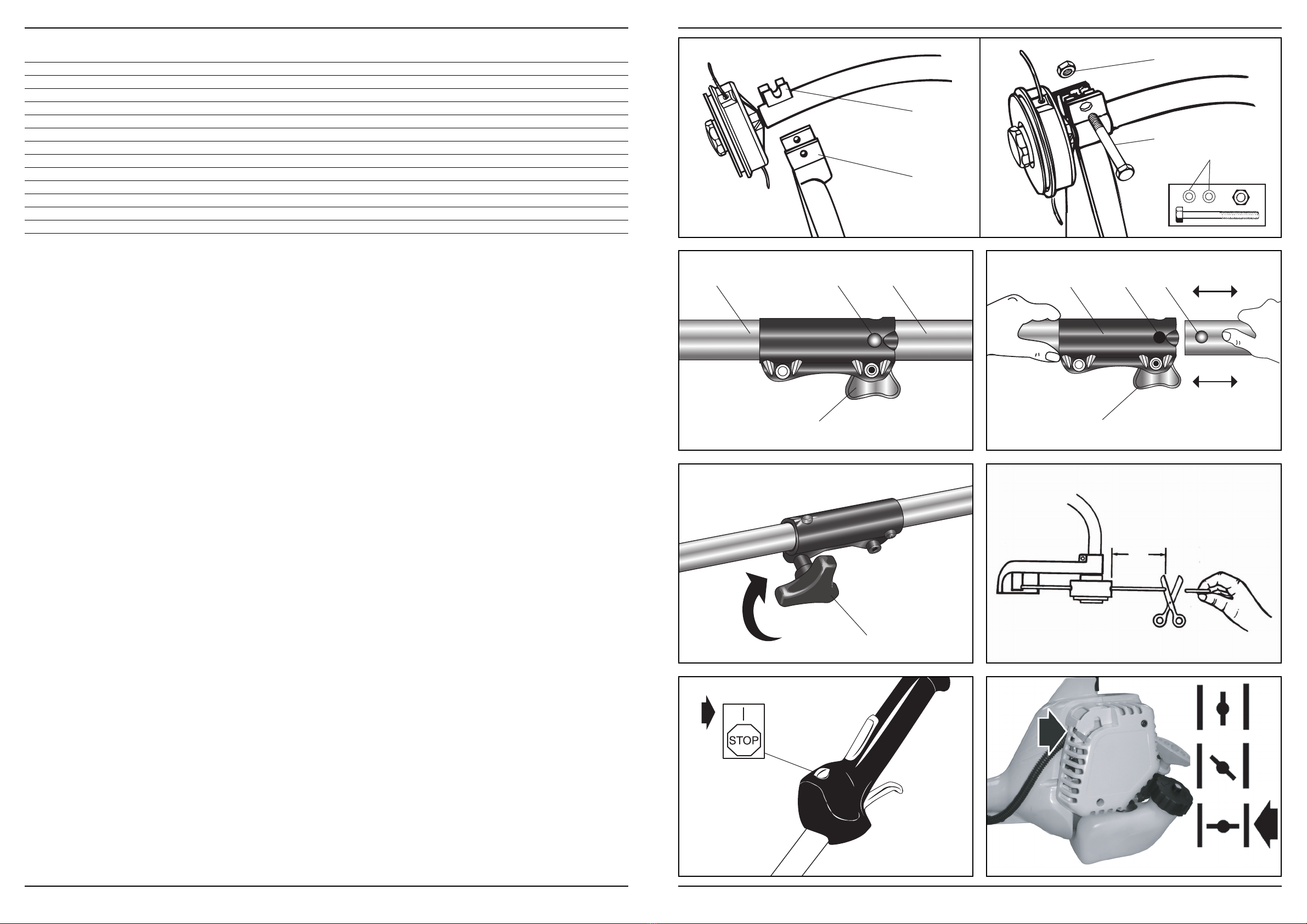
Arranquedeummotorfrio
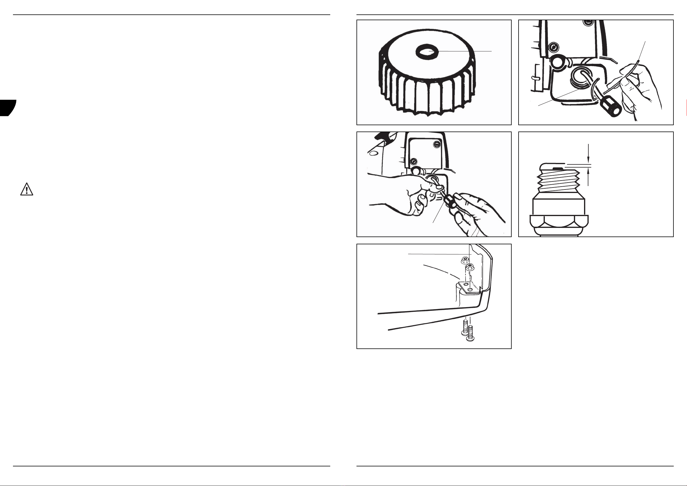
Fig. 5a - 5h
Nota:Paraminimizara carga no motor durante o arranque e o aquecimento, corte o excesso de linha para além dos 13 cm.
• Coloqueodispositivodeparagemdomotornaposição”MARCHA”“I”.
• Oequipamentodispõedeumobturadordearranquede3posições:“OBTURADOR”,“PARCIAL”e“MARCHA“.Desloqueo botão do
obturadordearranquenaposição“OBTURADOR”.
• Ligueocarburador. Carregue 10 vezes na bomba (A).
• Énecessáriaumatracçãorápidaesuaveparaconseguirumafaíscaforte.Puxecomforçaacordadearranque4vezes.
• Coloqueapatilhadoobturadornaposição“PARCIAL”.
• Puxenovamenteacordadearranque4vezesenquantoo gatilho estiver na posição de aceleração máxima.
• Quandoomotorarrancar, deixe o gatilho na posição “PARCIAL” durante 10 segundos.
• Desloqueoobturadorparaa posição “MARCHA“.
• Seomotornãoarrancar, repita os passos 1 a 7.
Nota:Seo motor não arrancar após várias tentativas, consulte a Secção Resolução de problemas.
Nota:Puxesemprea corda de arranque totalmente para fora. Se puxar a corda de arranque num determinado ângulo, a corda pode roçar no
olhal.Estafricçãopodetornaracordamaisfrágiledesgastá-lacommaiorrapidez.Seguresemprea pega da corda de arranque quando
acordavoltarparatrás.Nuncadeixequeacordachicoteieparatrása partir da posição esticada. Isto pode fazer com que a cordafique
desgastada,podendotambémdanificaracaixadomotordearranque.
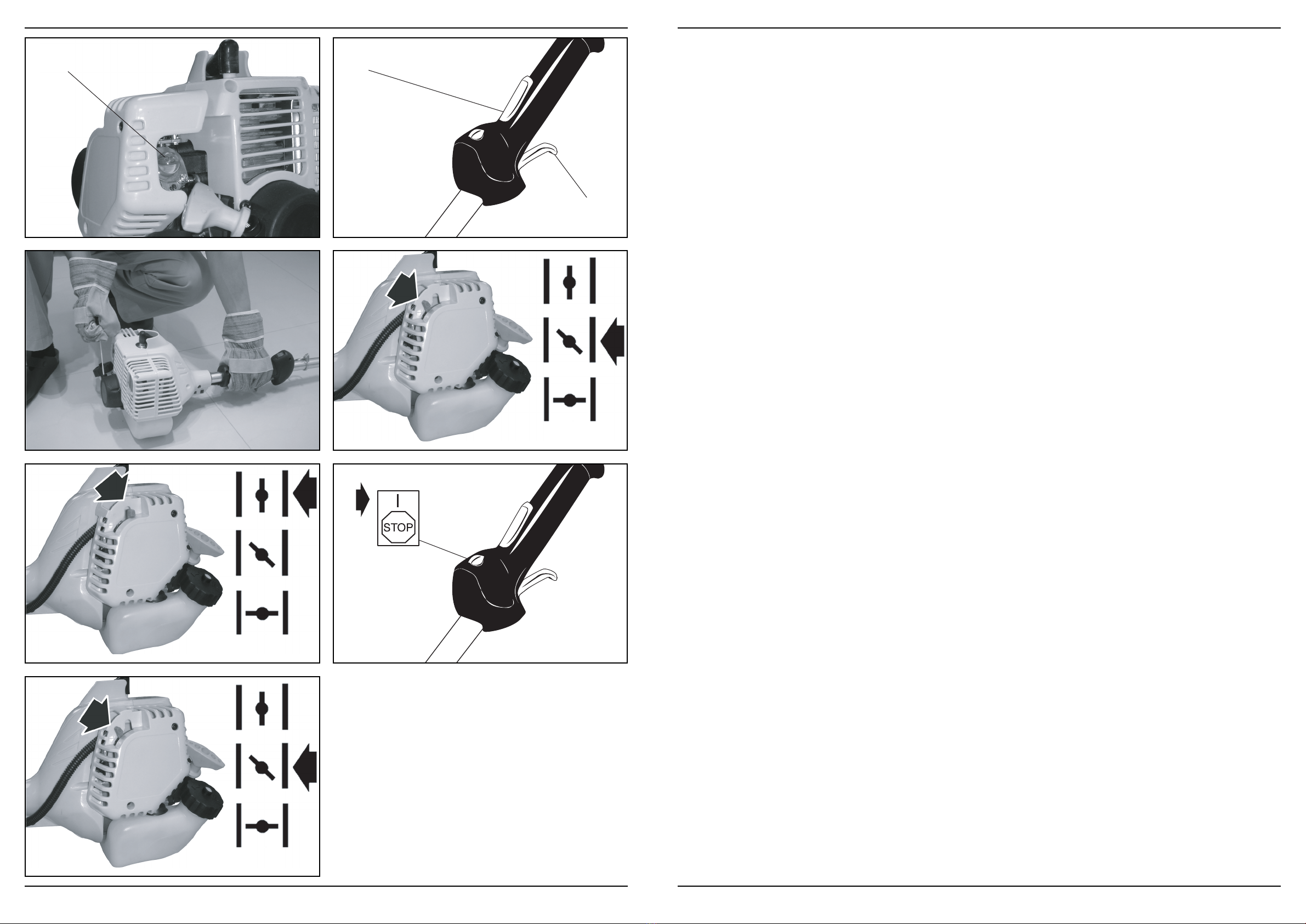
Arranquedeummotorquente
Fig. 6a - 6b
• Coloqueodispositivodeparagemdomotornaposição“MARCHA“.
• Coloqueoobturadornaposição“MARCHA“.
• Agarrecomfirmezaapegadoacelerador, coloque o interruptor de aceleração na posição “TOTAL”.
• Puxeacordadearranquecomforçaatéo motor arrancar, mas faça-o apenas 6 vezes. Mantenha o acelerador na posição”TOTAL” até
omotorcomeçarafuncionarsuavemente.
• Seomotornãoarrancar, coloque o obturador na posição “MARCHA“ e puxe a corda de arranque até 5 vezes. Se, mesmo assim, o motor
nãoarrancar, está provavelmente afogado.Aguarde5 minutos e repita o processo com o obturador na posição “MARCHA“ e com
oaceleradortotalmenteaberto.
Paraparaomotor
Solteogatilhodaválvuladeborboleta.Deixequeo motor passe para a velocidade ao ralenti. Empurre e mantenha premido o interruptorde
paragemdeigniçãoatéqueomotorpare.
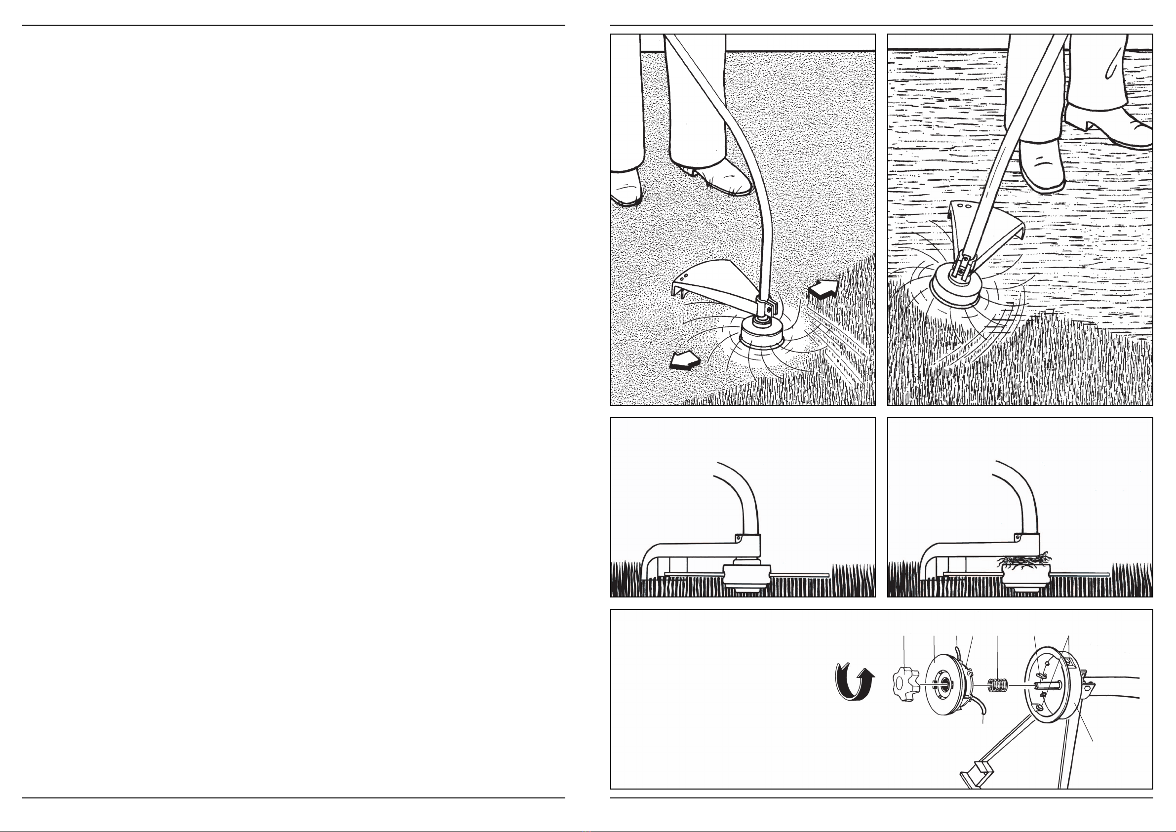
Procedimentosdecorte
Seoequipamentodispuserdeumaprotecçãoparao acessório de corte e uma cabeça de corte, é possível cortar ervas daninhas pequenas
erelvaaltaemáreasdedifícilacesso-juntoasebes,paredes,alicerceseàvoltadeárvores.Tambémpode ser utilizado para remover
vegetaçãorenteaochão,permitindoassimumapreparaçãomaisfácildeumjardimoualimpezadeumadeterminadaárea.
Nota:Mesmoefectuadocomcuidado,o corte à volta de alicerces, paredes de pedra ou tijolos, curvas, etc., resulta num maior desgastedo
fio.
Ferm 55
GB
D
NL
F
E
P
• Wearclose fitting, tough work clothing that will provide protection, such as long slacks or trousers, safety work shoes, heavy duty work
gloves,hardhat,aprotectivefaceshield,orsafetyglassesforeyeprotectionanda good grade of ear plugs or other sound barrierfor
hearingprotection.
• Refuelinasafeplace.Openfuelcapslowlytoreleaseanypressurewhichmaybepresentinthefueltank.Toprevent a fire hazard, move
atleast10feet(3meters)fromtherefuellingareabeforestarting.
• Complywithallfirepreventionregulations.Compliancewithalllocal,state,orfederallawsintheUnitedStatesistheresponsibilityofthe
user. Yourunit comes with a spark arrester screen furnished in the user kit. Replacement spark arrester screen kits are available from
yourdistributor.
• Turntheunitoffbefore setting it down.
• Alwaysholdtheunitfirmlywithbothhands,withthumbandfingersencirclingthehandles.
• Keepallscrewsandfastenerstight.Neveroperateyourequipmentwhenitisincorrectlyadjustedornotcompletelyandsecurely
assembled.
• Keephandlesdry,cleanandfreeoffuelmixture.
• Keepstringheadasclosetothegroundaspractical.Avoidhittingsmallobjectswiththestringhead.Whencuttingonaslope,standbelow
thestringhead.NEVERcutortrimonahillorslope,etc.ifthereistheslightestchanceofslipping,slidingorlosingfirmfooting.
• Checktheareayouwillbetrimmingfordebristhatmaybestruckorthrownupduringoperation.
• Keepallpartsofyourbodyandclothingawayfromthestringheadwhenstartingorrunningtheengine.Beforestartingtheengine,make
surethestringheadwillnotcomeintocontactwithanyobstacle.
• Stoptheenginebeforeexaminingthecuttingline.
• Storeequipmentawayfrompossibleignitionsources,suchaspetrol-poweredwaterheaters,clothesdryers,oroil-firedfurnaces,
portableheaters,etc.
• Alwayskeepthedebrisshield,stringhead,andenginefreeofdebrisbuild-up.
• Operationofequipmentshouldalwaysberestrictedtomatureandcorrectlyinstructedindividuals.
• WARNING:The emission of exhaust gases is toxic.
• EmergencyStoppingProcedure.Whenitisnecessarytostopengineimmediately,DEPRESStheswitchtostop.
• Thisunithasaclutch,routinesforcheckingthatthecuttingattachmentstopsturningwhentheengineidles.
Whatnottodo
• DONOTUSEANYOTHER FUELotherthanthatrecommendedinyourmanual.Always follow the instructions in the Fuel and
LubricationSectionofthismanual.Neverusepetrolunlessitiscorrectlymixedwith2-cycleenginelubricant.Permanentdamagetothe
enginewillresult,invalidatingthemanufacturer’swarranty.
• DONOTSMOKE while refuelling or operating equipment.
• DONOTOPERATETHE UNIT WITHOUTAMUFFLER and correctly installed muffler shield.
• DONOTTOUCHor let your hands or body come into contact with a hot muffleror spark plug wire.
• DONOTOPERATETHE UNIT INAWKWARD POSITIONS, off balance, outstretched arms, or one-handed.Always use two hands
whenoperatingunitwiththumbsandfingersencirclingthehandles.
• DONOTRAISETHE STRINGHEAD above ground level while the unit is operating. Injury to operator could result.
• DONOTUSETHE UNIT FORANY PURPOSES OTHER than trimming lawn or garden areas.
• DONOTOPERATETHE UNIT FOR PROLONGED PERIODS. Rest periodically.
• DONOTOPERATETHE UNIT WHILE UNDERTHE INFLUENCE OFALCOHOLORDRUGS.
• DONOTOPERATETHE UNIT UNLESSTHE DEBRIS SHIELDAND/ORGUARDISINSTALLEDAND IN GOOD CONDITION.
• DONOTADD,REMOVEORALTERANYCOMPONENTS OFTHIS PRODUCT.Doing so could cause personal injury and/or damage
theunitinvalidatingthemanufacturer’swarranty.
• DONOToperate your unit near or around inflammable liquids or petroles whether inside or outdoor.An explosion and/or fire can result.
• DONOTUSEANYOTHER CUTTINGATTACHMENT.Use only replacement parts and accessories, which are designed specifically to
enhancetheperformanceandmaximizethesafeoperationofourproducts.Failuretodosomaycausepoorperformanceandpossible
injury.Useonlythestringheadsuppliedwiththisproduct.Donotuseanyothercuttingattachment.Useofsuchattachmentswill
invalidateyourfactorywarrantyandcouldresultinseriousbodilyinjury.
Additionalsafetyprecautions
Before operating your unit, please reviewALL SAFETYPRECAUTIONS in this manual.
• IFUNFAMILIAR WITH TRIMMING techniques, practice the procedures with the ENGINE in “OFF” position.
• ALWAYSCLEARWORKareaofdebrissuchascans,bottles,rocks,etc.Strikingobjectscancauseseriousinjurytotheoperatoror
bystandersandalsodamageequipment.Ifanobjectisaccidentallyhit,immediatelyTURNTHE ENGINE OFF and examine equipment.
Neveroperatetheunitwithdamagedordefectiveequipment.
• ALWAYSTRIM OR CUTATHIGH ENGINE SPEEDS. Do not run the engine slowly when starting or during trimming operations.
• DONOTuse the equipment for purposes other than trimming or mowing weeds.
• NEVERraisethestringheadabovekneeheightduringoperation.
• DONOToperate the unit with other people or animals in the immediate vicinity.Allowa minimum of 50 feet (15 meters) between the
operatorandotherpeopleandanimalswhentrimmingormowing.Allow a distance of 100 feet (30 meters) between the operator and
otherpeopleandanimalswhenSCALPINGwiththestringheadcutter.
• IFOPERATINGTHE UNITONASLOPE, stand below the cutting attachment. DO NOT OPERATE on a slope or hilly incline if there is the
slightestchanceofslippingorlosingyourfooting.
10 Ferm
GB
D
NL
F
E
P

3.ASSEMBLYINSTRUCTIONS
Please install the unit according to the assembly instructions, or else it can be dangerous for the operator.
“P”handleinstallation
Fig. 2
• Toinstallthehandleontotheunit,youwillneedthefollowingcomponentsfromyouruserkit:handle(A& B), screws (C) and nuts (D).
• Installthehandle(B)ontheshaft160-200mmfromthrottleandtightenthe2screws(C)andnuts(D).
Installingthecuttingattachementguard
Fig. 3
The cutting attachment guard must be installed to cover the cutting attachment and protect the operator.
Theshieldfitssnugontheshaft.Someforcemayberequired.
• Positionshield(B)ontoshaftbracket(C).
• Insertwashers(D)ontobolt.
• Insertbolt(E)andtightennut(F)securely.
Installingtheattachement
Fig. 4a - 4c
To avoid serious personal injury, turn the unit off before removing or installing the attachment.
Note:To make installing or removing the attachment easier,place the unit on the ground or on a work bench.
• Turntheknob(A)counterclockwisetoloosen.
• Whilefirmlyholdingtheattachment(B),pushitstraightintothequickchangecoupler(C)untilthereleasebutton(D)appearsinthe
primaryhole(E)ofthequick-changecoupler.
• Turntheknob(A)clockwisetotighten.
The release button must be in the primary hole and the knob must be tightened securely before operating the unit.
Allattachmentsaredesignedtobeusedintheprimaryholeunlessotherwiseindicatedintheoperatormanualforspecificattachments.Ifthe
incorrectholeisused,itcanresultininjury,ordamagetotheunit.
Fuelandlubrication
Fuel
Useregulargradeunleadedpetrolmixedwith40:1custom2-cycleengineoilforbestresults.UsemixingratiosasintheFUELMIXING
TABLE.
Never use straight petrol in your unit. This will cause permanent engine damage and invalidate the manufacturer’s warranty for
that product. Never use a fuel mixture that has been stored for over 90 days.
If a 2-cycle lubricant other than custom lubricant is to be used, it must be a premium grade oil for 2-cycle air cooled engines mixed
at a 40:1 ratio. Do not use any 2-cycle oil product with a recommended mixing ratio of 100:1. If insufficient lubrication is the cause
of engine damage, it will invalidate the manufacturer’s engine warranty.
Mxing fuel
Addtheoiltoanapprovedfuelcontainerfollowedbythepetroltoallowincomingpetroltomixwiththeoil.Shakethecontainertoensure
thoroughmixing.
Lack of lubrication invalidates the engine warranty. Petrol and oil must be mixed at 40:1.
Ferm 11
GB
D
NL
F
E
P
• NUNCAlevante a cabeça de corte acima do joelho durante o funcionamento.
• NÃOutilizeoequipamentopróximodepessoasouanimais.Mantenhaumadistânciamínimade15metrosentreo operador e outras
pessoasouanimaisduranteasoperaçõesdecorteouquandoaparar. Mantenha uma distância de 30 metros entre o operador e outras
pessoasouanimaisquandoAPARAR com a unidade de cabeça de corte.
• SE UTILIZAR O EQUIPAMENTO NUMAZONAINCLINADA, coloque-se abaixo do acessório de corte. NÃO UTILIZE O equipamento
numazonamuitoinclinadasehouveramínimaprobabilidadededeslizaroudesequilibrar-se.
3. INSTRUÇÕESDEMONTAGEM
Monte o equipamento de acordo com as instruções de montagem, caso contrário pode constituir um perigo para o operador.
Montagemdapegaem“P”
Fig. 2
• Paramontarapeganoequipamento,sãonecessáriososseguintescomponentesdokitdeutilizador:pega(A& B), parafusos (C) e
porcas(D).
• Monteapega(B)noveioa uma distância de 160-200 mm do acelerador e aperte os 2 parafusos (C) e porcas (D).
Montagemdaprotecçãodoacessóriodecorte
Fig. 3
Aprotecção do acessório de corte deve ser instalada para tapar o acessório de corte e proteger o operador.
Aprotecção deve ser devidamente instalada no veio. Pode ser necessário aplicar alguma força.
• Posicioneaprotecção(B)nosuportedoveio(C).
• Coloqueasanilhas(D)noparafuso.
• Insiraoparafuso(E)eapertefirmementea porca (F).
Montagemdoacessório
Fig. 4a - 4c
Para evitar lesões pessoais graves, desligue o equipamento antes de remover ou montar o acessório.
Nota:Parafacilitara montagem ou remoção do acessório, coloque o equipamento no chão ou numa bancada.
• Rodeobotão(A)nosentidoopostoaodosponteirosdorelógioparadesapertaro acessório.
• Mantendooacessóriofirmementefixo(B),empurre-odirectamenteparao conector de mudança rápida (C) até o botão de libertação(D)
aparecernoorifícioprincipal(E)doconectordemudançarápida.
• Rodeobotão(A)nosentidodosponteirosparaapertá-lo.
O botão de libertação deve estar colocado no orifício principal e o botão devidamente fixo antes de utilizar o equipamento.
Todososacessóriosforamconcebidosparaseremutilizadosnoorifícioprincipal,exceptoindicaçãoemcontrárionomanualdoutilizador
relativosaacessóriosespecíficos.Seforutilizadoo orifício incorrecto, isso pode dar origem a danos no equipamento.
Combustívelelubrificação
Combustível
Utilizegasolinasemchumbonormalmisturadacomóleoparamotorde2tempos40:1paraobterosmelhoresresultados.Utilizeasrelações
demisturaindicadasnaTABELADEMISTURADECOMBUSTÍVEL.
Nunca utilize gasolina normal no equipamento. Isto pode causar danos permanentes no motor e invalidar a garantia do
fabricante respeitante a este equipamento. Nunca utilize uma mistura de combustível que tenha sido armazenada há mais de 90
dias.
Se utilizar um lubrificante de 2 tempos diferente do lubrificante de origem, deve utilizar um óleo de elevada qualidade para
motores de 2 tempos com refrigeração a ar, misturada numa proporção de 40:1. Não utilize um óleo de 2 tempos com uma
relação de mistura recomendada de 100:1. Se se verificarem danos do motor devido a lubrificação insuficiente, isso invalida
a garantia do fabricante do motor.
Misturar combustível
Deiteoóleonumdepósitodecombustívelaprovadoeadicionegasolinaparaqueestasemisturecomo óleo.Agite o depósito para garantir
umamisturacompleta.
54 Ferm
GB
D
NL
F
E
P

• Usevestuáriojustoparatrabalhospesadosquesirvadeprotecção,taiscomocalçascompridaslargas,calçadodesegurança,luvasde
trabalhoresistentes,capacetedesegurança,máscaradeprotecçãoouóculosdesegurançaparaprotecçãodosolhosetampões
adequadosparaosouvidosououtrotipodeprotecçãoauricular.
• Reabasteçanumlocalseguro.Abra lentamente a tampa do depósito para libertar qualquer pressão existente no depósito de
combustível.Paraevitaroriscodeincêndio,afaste-se,pelomenos,3metrosdaáreadereabastecimentoantesdereabastecer.
• Cumpratodasasregulamentaçõesdeprevençãodeincêndios.Ocumprimentodetodaa legislação local ou estatal em Portugal é da
responsabilidade do utilizador. O equipamento é fornecido com uma protecção contra faíscas incluída no kit de utilizador. Para
substituição,osdistribuidoresdispõemdekitsdeprotecçãocontrafaíscas.
• Desligueoequipamentoantesdeo colocar no chão.
• Agarresemprecomfirmezaoequipamentocomambasasmãos,demodoa rodear as pegas com o polegar e os outros dedos.
• Mantenhatodososparafusosefixadoresapertados.Nuncautilizeoequipamentosenãoestiverajustadocorrectamenteousenão
estiverdevidaoutotalmentemontado.
• Mantenhaaspegassecas,limpasesemmisturadecombustível.
• Mantenhaacabeçadecorteo mais próximo possível do chão. Evite tocar em objectos pequenos com a cabeça de corte. Quando cortar
numdeclive,coloque-seabaixodacabeçadecorte.NUNCAcorte nem apare numa colina ou declive, etc. se houver o risco de
escorregar, deslizar ou de desequilibrar-se.
• Verifique se, na área que pretende aparar, existem fragmentos que possam ficar presos ou ser projectados durante o funcionamento.
• Mantenhaqualquerpartedocorpoouvestuárioafastadosdacabeçadecortequandoarrancarouutilizaromotor.Antesde ligar o motor,
certifique-sedequeacabeçadecortenãoentraemcontactocomqualquerobstáculo.
• Pareomotorantesdeexaminara linha de corte.
• Guardeoequipamentolongedepossíveisfontesdeignição,taiscomoaquecedoresdeáguaa gasolina, secadores de roupa ou fornos
aóleo,aquecedoresportáteis,etc.
• Mantenhasempreaprotecçãocontrafragmentos,cabeçadecorteemotorsemacumulaçãodefragmentos.
• Oequipamentodeveserapenasutilizadoporadultosdevidamentehabilitados.
• ADVERTENCIA:Los gases de escape emitidos son tóxicos.
• Paradadeemergencia.Siesnecesariopuededetenerelmotorinmediatamente,PRESIONANDOelinterruptordeparada(STOP).
• Lamáquinaestáequipadaconunembragueyunsistemaquedetectasielaccesoriodecortehadejadodegirarcuandoelmotorestá
aralentí.
Oquenãodevefazer
• NÃOUTILIZEUMCOMBUSTÍVELquenão seja o recomendado no manual. Siga sempre as instruções indicadas na Secção
CombustíveleLubrificaçãodestemanual.Nuncautilizegasolina,amenosquetenhasidodevidamentemisturadacomumlubrificante
paramotorde2tempos.Podemocorrerdanospermanentesnomotor, invalidando a garantia do fabricante.
• NÃOFUMEduranteoreabastecimentooufuncionamentodoequipamento.
• NÃO UTILIZE O EQUIPAMENTO SEM UM SILENCIADOR e uma protecção para silenciador devidamente instalada.
• NÃOTOQUEnem coloque as mãos ou outra parte do corpo sobre um silenciador quente ou o fio das velas de um motor.
• NÃO UTILIZE O EQUIPAMENTO EM POSIÇÕES INVULGARES, tais como em equilíbrio precário, com os braços esticados ou apenas
comumamão.Quandoutilizaroequipamento,agarre-osemprecomambasasmãos,envolvendoaspegascomospolegareseos
outrosdedos.
• NÃOLEVANTEACABEÇADE CORTEacima do nível do chão enquanto o equipamento estiver em funcionamento. Isso pode provocar
lesõesnooperador.
• NÃO UTILIZE O EQUIPAMENTO PARAQUAISQUER FINS, excepto para aparar relva ou áreas de jardim.
• NÃO UTILIZE O EQUIPAMENTO DURANTE PERÍODOS DETEMPO PROLONGADOS. Descanse regularmente.
• NÃO UTILIZE O EQUIPAMENTO SOB O EFEITO DE ÁLCOOLOU DROGAS.
• NÃO UTILIZE O EQUIPAMENTO SEMAPROTECÇÃO CONTRAFRAGMENTOS E/OU SEMAPROTECÇÃO INSTALADAE EM
BOMESTADO.
• NÃOINSTALE,RETIRENEMMODIFIQUEQUAISQUERCOMPONENTESDESTEEQUIPAMENTO.Se o fizer,pode causar lesões
pessoaise/oudanosnoequipamento,invalidandoagarantiadofabricante.
• NÃOutilizeoequipamentopertodelíquidosougasesinflamáveis,quersejaeminterioresouexteriores.Podeocorrerumaexplosão
e/ouincêndio.
• NÃOUTILIZEQUALQUEROUTROACESSÓRIO DE CORTE.Utilizeapenaspeçaseacessóriosdesubstituiçãoda,concebidos
especialmenteparamelhorarodesempenhoemaximizaro funcionamento seguro dos nossos produtos. Se não o fizer, isso pode
resultarnumdesempenhoreduzidoeempossíveislesões.Utilizeapenasacabeçadecortefornecidacomesteequipamento.Não
utilizequalqueroutroacessóriodecorte.Autilizaçãode outros acessórios invalida a garantia de fábrica e pode resultar em lesões
corporaisgraves.
Precauçõesadicionaisdesegurança
Antes de utilizar o equipamento, reveja TODASAS PRECAUÇÕES DE SEGURANÇA indicadas neste manual.
• SENÃOESTIVERFAMILIARIZADO COMASTÉCNICAS PARAAPARAR, pratique primeiro com o MOTORna posição “OFF”
(Desligado).
• MANTENHASEMPREAÁREAlimpade resíduos, tais como latas, garrafas, pedras, etc. Se bater em objectos, pode dar origem
alesõesgravesnooperadorouemtranseuntesedanificartambémoequipamento.Sebaterporacasonumobjecto,DESLIGUE
IMEDIATAMENTEoequipamentoeverifique-o.Nuncautilizeoequipamentoseestiverdanificadooudefeituoso.
• APAREOUCORTESEMPREAVELOCIDADES ELEVADAS. Não utilize o motor a velocidades reduzidas quando iniciar ou efectuar
operaçõesdeaparar.
• NÃOutilizeoequipamentoparaoutrosfinsalémdeapararoucortarervasdaninhas.
Ferm 53
GB
D
NL
F
E
P
Fuel mixing table
Petrol 40:1RatioCustomLubricant
1U.S.Gal. / 3.2 oz. 95 ml (cc)
5Litres/4.3oz. 125ml(cc)
1lmp.Gal. / 4.3 oz. 125 ml (cc)
MixingProcedure:
40PartsPetrolto1partLubricant
1ml=1cc
Recommended fuels
Someconventionaltypesofpetrolareblendedwithoxygenatessuchasalcoholoranethercompoundtomeetcleanairstandards.Your
engineisdesignedtooperatesatisfactorilywithanypetrolintendedforautomotiveuseincludingoxygenatedpetrol.
4.OPERATING INSTRUCTIONS
Startingcoldengine
Fig. 5a - 5h
Note:Tominimizetheloadontheengineduringstartingandwarm-up,trimtheexcesscutterlineto13cm.
• Movetheenginestoppingdeviceto“RUN”“(I)”position.
• Your unit is designed with a 3 position choke: “CHOKE”, “PARTIAL”, and “RUN”. Move choke lever to “CHOKE” position.
• Primethecarburettor. Pump the primer bulb (A) 10 times.
• Asmooth rapid pull is required for a strong spark. Pull the starter rope briskly 4 times.
• Movethechokeleverto“PARTIAL”position.
• Pullthestarterropeagain4timeswhilethetriggerisinthefullthrottleposition.
• Oncetheenginestarts,leavein“PARTIAL”position for 10 seconds.
• Movethechoketo“RUN”position.
• Iftheenginefailstostart,repeatsteps1to7.
Note: If the engine fails to start after repeated attempts, refer to theTroubleshootingSection.
Note:Always pull the starter rope straight out. Pulling the starter at an angle will cause the rope to rub against the eyelet.Thisfrictionwill
causetheropetofrayandwearmorequickly.Always hold the starter handle when the rope retracts. Never allow the rope to snap back from
theextendedposition.This could cause the rope to snag or fray and also damage the starter assembly.
Startingwarmengine
Fig. 6a - 6b
• Movetheenginestoppingdeviceto“RUN”position.
• Placethechokein“START”position.
• Graspthethrottlehandlefirmly,squeezethethrottletriggertoFULLposition.
• Pullthestarterropebrisklyuntiltheenginestarts,butnomorethan6times.Keepthethrottleat“FULL”positionuntiltheengineruns
smoothly.
• Iftheenginedoesnotstart,placethechokein“RUN”positionandpullthestarterrope5moretimes.Iftheenginestilldoesnotstartitis
probablyflooded.Wait5minutesandrepeatprocedurewiththechokein“RUN”positionandthethrottlefullopen.
Tostopengine
Releasethethrottletrigger. Let the engine return to idle. Push and hold the ignition stop switch until the engine stops.
Trimming instructions
Whencorrectlyequippedwithacuttingattachmentguardandcuttinghead,yourunitwilltrimunsightlyweedsandtallgrassinthosehard-to-
reachareas-alongfences,walls,foundationsandaroundtrees.Itcanalsobeusedforscalpingtoremovevegetationdowntothegroundfor
easierpreparationofagardenortocleanouta particular area.
Note: Even with care, trimming around foundations, brick or stone walls, curves, etc., will result in above average line wear.
Trimming/mowing
Fig. 7a
Swingthetrimmerwithasickle-likemotionfromsidetoside.Donottiltthecuttingheadduringtheprocedure.Test the area to be trimmed for
correctcuttingheight.Keepthecuttingheadatthesamelevelforanevendepthofcut
Closer trimming
Positionthetrimmerstraightaheadwithaslighttiltsothebottomofcuttingheadisabovegroundlevelandlinecontactoccursatthecorrect
cuttingpoint.Always cut away from the operator.Donotpullthetrimmerintowardtheoperator.
Fence/foundation trimming
Approachtrimmingaroundchainlinkfences,picketfences,stonewallsandfoundationsslowlytocutclosewithoutwhippingthelineagainst
thebarrier. If the line comes into contact with rocks, brick walls, or foundations, it will break or fray. If the line snags on fencing, it will snap.
12 Ferm
GB
D
NL
F
E
P

Trimming around trees
Trimaroundtreetrunkswithaslowapproachsothelinedoesnotmakecontactwiththebark.Walkaroundthetreetrimmingfromlefttoright.
Approachgrassorweedswiththetipofthelineandtiltthecuttingheadslightlyforward.
Scalping
Fig. 7b
Use extreme caution when SCALPING. Keep a distance of 100 feet (30 meters) between the operator, other people and animals
during these operations.
Scalpingreferstoremovalofallvegetationdowntotheground.To do this, tilt the cutting head to about a 30 degree angle to the left. By
adjustingthehandleyouwillhavebettercontrolduringthisoperation.Donotattemptthisprocedureifthereisanychanceflyingdebriscould
injuretheoperator, other people or cause damage to property.
Do not sweep with trimmer
Sweepingreferstotiltingthelineheadtosweepawaydebrisfromwalkways,etc.Yourtrimmer is a powerful tool and small stones or other
suchdebriscanbehurled50feet(15meters)ormore,causinginjuryordamagetonearbypropertysuchasautomobiles,homesand
windows.
Cuttingheadlinerelease
Fig. 8a - 8b
DO NOT use steel wire or plastic coated steel wire of any type with your linehead. Serious operator injury can result.
Toreleaseafreshline,runtheengineatfullthrottleand“bump”thecuttingheadagainstthelawn.The line will automatically release.The
knifeinthecuttingattachmentguardwilltrimtheexcessline.
Periodically remove weed wrap to prevent overheating of the drive shaft. Weed wrap occurs when strands of weed become
entangled around the shaft beneath the cutting attachment guard. This condition prevents the shaft from cooling properly.
Remove weed wrap with a screwdriver or similar device.
5.MAINTENANCE
Trouble shooting the engine
Replacingtrimmingline-Standardhead
Fig. 5a, 9a - 9g
• Turnknob(A)COUNTERCLOCKWISEandremove.Usethebumpknobspannersupplied.
• Removespool(B)andspring(C)fromspindle(D).
• Removeanyremainingtrimmingline(H).
• Doublea14‘(4.3m)lengthof.080“(2mm)trimmingline.Placetheloopedcentreinoneoftheslotsofthespooldivider.
• Windthetrimminglineclockwiseasshowninillustration,keepingthetension,witheachhalfseparatedbythespooldivider. Wind to
within6“(15cm)oftheends.
• Lockeachendofline(H)intoaslot(F)onoppositesidesofthespool.
Problem Probablecause Correctiveaction
Unitwillnotstartorstartsbutwillnotrun. Incorrectstartingprocedures. FollowinstructionsintheUserManual.
Incorrectcarburettormixtureadjustment
setting.
HavecarburettoradjustedbyanAuthorised
ServiceCentre.
Soiledsparkplug Clean/gaporreplaceplug.
Fuelfilterplugged. Replacefuelfilter.
Unitstarts,butenginehaslowpower. Incorrect lever position on choke. Moveto“RUN”position.
Dirtyairfilter. Remove, clean and reinstall filter.
Incorrectcarburettormixtureadjustment
setting.
HavecarburettoradjustedbyanAuthorised
ServiceCentre.
Enginehesitates.
Nopowerunderload.
Incorrectcarburettormixtureadjustment
setting.
HavecarburettoradjustedbyanAuthorised
ServiceCentre.
Runserratically. Incorrectlygappedsparkplug. Clean/gaporreplaceplug.
Smokesexcessively. Incorrectcarburettormixtureadjustment
setting.
HavecarburettoradjustedbyanAuthorised
ServiceCentre.
Incorrectfuelmixture. Usecorrectlymixedfuel(40:1mixture).
Ferm 13
GB
D
NL
F
E
P
* Fornecido com o kit de utilizador
Nota:NÃOutilizelâminascomestemodelo.
Oquedevefazer
3APROTECÇÃO DOACESSÓRIODE CORTE deve estar instalada para impedir que o operador seja atingido por acaso por quaisquer
fragmentoseparaevitarqueofiosejaesticadoparaalémdonecessário.
14 APROTECÇÃO DO SILENCIADOR impede que as mãos, o corpo e/ou materiais combustíveis entrem em contacto com um silenciador
quente.
2.SEGURANÇA
Significadodossímbolosindicadosnoequipamento
Leia o manual do utilizador antes de utilizar o equipamento
Este símbolo, juntamente com as indicações aviso! e perigo! chama a atenção para uma acção ou condição que pode dar
origem a lesões pessoais graves no operador ou em transeuntes.
Aviso! Superfície quente
Aviso! Lâminas em rotação!As unidades de corte continuam a rodar depois do motor estar desligado
Tenha cuidado com objectos projectados
Não utilize lâminas metálicas
Mantenha as pessoas ou animais a uma distância de, pelo menos, 15 m do equipamento quando estiver a funcionar
Sempre que utilizar o equipamento, deve usar óculos de segurança para se proteger de objectos projectados, devendo usar
também protecção auricular, tal como um capacete à prova de ruído, para proteger os ouvidos do operador. Se o operador
estiver a trabalhar numa área onde houver risco de queda de objectos, deve usar também um capacete de segurança.
Use luvas para proteger as mãos
Use botas de segurança para se proteger contra choques eléctricos
Bomba.
Nível de potência acústica LWAde acordo com a directiva 2000/14/CE
Se utilizar equipamento com motor a gasolina, devem ser sempre tomadas medidas básicas de segurança para reduzir o risco
de lesões pessoais graves e/ou danos no equipamento. Leia todas as instruções antes de utilizar este equipamento e guarde-as
num local seguro.
Oquedevefazer
Estaunidadedepotênciapodeserperigosa!Ooperadoréresponsávelpelocumprimentodomanualdoequipamentoedasrespectivas
instruçõeseavisos.Leiaomanualdeutilizadorporcompletoantesdeutilizaro equipamento! Esteja familiarizado com os controlose
autilizaçãocorrectadoequipamento.Autilizaçãodo equipamento deve restringir-se aos utilizadores que tenham lido, compreendido e
cumpridoasinstruçõeseavisosdomanualdooperador. Nunca deixe que crianças utilizem o equipamento.
Nunca utilize lâminas, arames ou dispositivos para cortar sebes. O equipamento foi concebido apenas para aparar arbustos.
Autilização de outros acessórios ou componentes aumenta o risco de lesões.
Mantenha as crianças, transeuntes e animais a uma distância de 15 metros. Se se aproximarem, pare imediatamente de utilizar
o equipamento.
52 Ferm
GB
D
NL
F
E
P

APARADOR DE RELVA A GASOLINA 28CC
Os números indicados no seguinte texto correspondem às figuras na página 2 - 7.
Leia e certifique-se de que compreende o conteúdo do manual antes de utilizar o equipamento. Guarde-o num local seguro para
referência futura. Inclui especificações e informações sobre funcionamento, arranque, paragem, manutenção, armazenamento
e instruções específicas de montagem para este equipamento.
Leia e certifique-se de que compreende as instruções de segurança antes de utilizar o equipamento. Guarde-o num local seguro
para referência futura. O manual explica possíveis perigos relacionados com a utilização deste equipamento e quais as medidas
a tomar para torná-lo mais seguro.
Introdução
Esteprodutofoiconcebidoefabricadoparaproporcionarumaduraçãoprolongadaefiabilidadeduranteofuncionamento.Leiao manuale
certifique-sedequecompreendeoconteúdo.Iráverificarqueéfácildeutilizaredispõedemuitassugestõesdefuncionamentoe
mensagensdesegurança.As especificações, descrições e imagens apresentadas neste manual são tão precisas quanto possível
aquandodapublicação,maspodemestarsujeitasaalteraçõessemavisoprévio.As imagens podem incluir equipamento e acessórios
opcionaisepodemnãoincluirtodooequipamentopadrão.
Índice
1. Característicastécnicasdamáquina
2. Segurança
3. Instruçõesdemontagem
4. Instruçõesdefuncionamento
5. Manutenção
1.CARACTERÍSTICASTÉCNICASDAMÁQUINA
Especificaçõestécnicas
Identificaçãogeral
Fig. 1
1. Cabeçadecorte
2. Linhaflexível
3. Protecçãodoacessóriodecorte
4. Haste
5. Pegaemformade“P”
6. Gatilhodaválvuladeborboleta
7. Dispositivodeparagemdomotor
8. Bloqueiodaválvuladeborboleta
9. Patilhadoobturador
10. Caixadacordadearranque
11. Depósitodecombustível
12. Tampadofiltrodear
13. Pegadearranque
14. Protecçãodosilenciador
15. Bomba
16. Porca,parafuso& anilhadaprotecçãodoacessóriodecorte*
17. Chavedeporcas
18. Conectordemudançarápida
Tipodemotor Refrigeraçãoaar, 2 tempos, cilindro cromático
Volume 28 cm3
Peso 4,7Kg
Cabeçaplana Alimentaçãodecabeçaplanacomlinhadupla
Comprimentodoveiodetransmissão 66cm+66cm
Larguradecorte 43cm
Pega Pegaemformade“P”
Ignição Electrónica
Transmissão Embraiagemcentrífuga
Níveldepressãoacústica 96,5dB(A)
Níveldepotênciaacústica 110dB(A)
Níveldevibraçãodeaceleração 5,75m/s2
Níveldevibraçãoemmarchalenta 2,0m/s2
Desempenhomáximodo motor 1,0kW
Frequênciamáximaderotaçãodoeixo 8500min-1
Velocidade ao ralenti 3200 ± 200 min-1
Consumodecombustível 620g/kWh
Ferm 51
GB
D
NL
F
E
P
• Installthespring(C)overthespindle(D).Inserteachendofthelinethroughaneyelet(G)inthehousing(E).
• Lowerthespoolintothehousing(E)whilefeedingthelinethroughtheeyelets(G).Ensurethespringpositionsitselfintothespool.
• Oncethespoolisinplace,applypressureonthespoolcompressingthespring.Pulleachendoftheline(H)sharplytounlocktheline
fromtheslots.
• ContinuetoapplypressuretothespooluntiltheknobcanbethreadedCLOCKWISEontothespindle.Tightenthe knob securely by hand
only.
• Trimtheexcesslinetoapproximately5“(13cm).This will minimize the load on the engine during starting and warm-up.
Air filter
Fig. 10
NEVER operate the trimmer without the air filter. The air filter must be kept clean. If it becomes damaged, then install a new filter.
Tocleanairfilter:
• Remove2screws(A)holdingtheairfiltercoverinplace,removecover(B)andliftthefilter(C)fromtheairbox.(Fig.9)
• Washthefilter in soap and water. DO NOT USE PETROL!
• Airdrythefilter.
• Reinstallthefilter.
Note:Replacefilteriffrayed,torn,damagedorunabletobecleane.
Fuelcap/fuelfilter
Fig. 11a - 11c
Remove fuel from the unit and store in an approved container before starting this procedure. Open the fuel cap slowly to release
any pressure which may be present in the fuel tank.
Note:Keepvent(A)onfuelcapcleanofdebris.
• Liftfuellineandfilter(B)outoftank.Asteelwire (C) with a hook or a paper clip works well.
• Pulloffwith a twisting motion.
• Replacefuelfilter(D).
Note:Neveroperatethetrimmerwithoutthefuelfilter. Internal engine damage could result!
Carburettoradjustment
Thecarburettorwaspre-setatthefactoryforoptimumperformance.Iffurtheradjustmentsarenecessary,pleasetakeyourunittothenearest
AuthorisedServiceCentre.
Sparkplug
Fig. 12
• Sparkpluggap=0.025“(0.635mm).
• Torqueto105to130inchpounds(12to15Nm).Connectsparkplugboot.
Cuttingattachmentguardknifesharpening
Fig. 13
• Removethecutterknife(E)fromthecuttingattachmentguard(F).
• Placetheknifeinabenchvice.Sharpentheknifeusinga flat file, being careful to maintain the angle of the cutting edge. Fileinone
directiononly.
Storingaunit
Failure to follow these steps may cause varnish to form in the carburettor and cause difficult starting or permanent damage
following storage.
• PerformallgeneralmaintenancerecommendedintheMaintenanceSectionofyourUserManual.
• Cleantheexterioroftheengine,driveshaftassembly,debrisshieldandstringhead.
• Drainfuelfromthefueltank.
• Afterfuelisdrained,starttheengine.
• Runtheengineatidleuntiltheunitstops.This will purge the carburettor of fuel.
• Allowtheenginetocool(approx.5minutes).
• Usingasparkplugwrench,removethesparkplug.
• Pour1teaspoonofclean2-cycleoilintothecombustionchamber. Pull the starter rope slowly several times to coat internal components.
Replacethesparkplug.
• Storetheunit in a cool, dry place away from any source of ignition such as an oil burner, water heater, etc.
14 Ferm
GB
D
NL
F
E
P

Removingtheunitfromstorage:
• Removethesparkplug.
• Pullthestarterropebrisklytoclearexcessoilfromthecombustionchamber.
• Cleanandgapthesparkplugorinstallanewsparkplugwiththecorrectgap.
• Preparetheunitforoperation.
• Fillthefueltankwiththecorrectfuel/oilmixture.SeeFuelandLubricationSection.
Faults
Shouldafaultoccur, e.g. after wear of a part, please contact the service address on the warranty card. In the back of this manual you find an
explodedviewshowingthepartsthatcanbeordered.
Environment
Inordertoavoiddamageduringtransport,thesawisdeliveredinstrongpackagingmaterial.Wherepossible,recyclablepackagingmaterial
hasbeenused.Therefore, please recycle the packaging material.
Warranty
Seethewarrantycardinthebackofthisinstructionmanualforthewarrantyterms.
CE DECLARATION OF CONFORMITY (GB)
Wedeclare under our sole responsibility that this product is in conformity with the following standards or standardized documents:
EN ISO11806, EN ISO14982, EN ISO3744
inaccordancewiththeregulations:
98/37/EC, 2000/14/EC
from01-07-2006
ZWOLLENL
J.A.Bakker-vanIngen J.Lodewijk
CEOFermBV QualityManagerFermGlobal
Itisourpolicytocontinuouslyimproveourproductsandwethereforereservetherighttochangetheproductspecificationwithoutprior
notice.
FermBV•Lingenstraat6•8028 PM Zwolle•TheNetherlands
Ferm 15
GB
D
NL
F
E
P
CE DECLARACIÓNDECONFORMIDAD (E)
Declaramosbajonuestraexclusivaresponsabilidadqueesteproductocumpleconlassiguientesnormasodocumentosnormalizados:
EN ISO11806, EN ISO14982, EN ISO3744
segúnlasregulaciones:
98/37/EC, 2000/14/EC
Del01-07-2006
ZWOLLENL
J.A.Bakker-vanIngen J.Lodewijk
CEOFermBV QualityManagerFermGlobal
Esnuestrapolíticamejorarcontinuamentenuestrosproductosyportantonosreservamoselderechoacambiarlascaracterísticasdel
productosinprevioaviso.
FermBV•Lingenstraat6•8028PMZwolle•Holanda
50 Ferm
GB
D
NL
F
E
P

Tapónyfiltrodeldepósitodecombustible
Fig. 11a - 11c
Extraiga la gasolina de la máquina y deposítela en un recipiente homologado antes de iniciar esta operación.Abra el tapón del
depósito de combustible lentamente para liberar con precaución la presión que pueda haberse creado en el interior.
Nota:Mantengaelrespiradero(A)deltapóndegasolinalimpio.
• Extraigaeltuboyelfiltrodegasolina(B)deldepósito.Utiliceparaellounganchodealambre(C)ounclipdeoficina.
• Extráigaloconunmovimientogiratorio.
• Sustituyaelfiltrodegasolina(D).
Nota:SEPROHÍBEutilizarlarecortadorasinelfiltrodegasolina,elmotorpodríaresultardañado.
Regulacióndelcarburador
Elcarburadorvienereguladodefábricaparaelrendimientoóptimo.Sifueranecesarioregularelcarburador, lleve la máquina al taller de
servicioautorizadomáspróximo.
Bujía
Fig. 12
• Separaciónentreloselectrodos=0,635mm(0,025“).
• Pardeapriete12a15Nm(105a 130 ft-lbs). Conecte el casquillo de la bujía.
Cuchilladelaproteccióndelaccesoriodecortaafilado
Fig. 12
• Desmontelacuchilla(E)delaproteccióndelaccesoriodecorte(F).
• Montelacuchillaenuntornodebanco.Afile la cuchilla con una lima plana, procurando mantener el ángulo del filo de corte. Lime sólo en
unadirección.
Almacenamiento
Si no se tienen en cuenta estos pasos, durante el almacenamiento puede formarse barniz en el carburador, causando la avería
o que la máquina arranque con dificultad.
• Realiceelmantenimientogeneralqueserecomiendaenelapartado„Instruccionesdemantenimiento“deestemanual.
• Limpieelexteriordelmotor, la unidad del eje de accionamiento, el faldón de protección y el cabezal de corte.
• Extraigalagasolinadeldepósito.
• Unavezextraídoelcombustible,arranqueelmotor.
• Dejeelmotoraralentíhastaquesedetengalaunidad.Estopurgaráelcarburadordegasolina.
• Dejequeelmotorseenfríe(duranteaprox.5minutos).
• Desmontelabujíaconunallavedebujía.
• Viertauna cuchara de aceite para motores de 2 tiempos limpia en la cámara de combustión.Tirea continuación de la cuerda del motor
dearranquelentamenteenvariasocasionesparaqueelaceitecubraloscomponentesinternos.Sustituyalabujía.
• Almacenelamáquinaenunlugarfresco,secoyalejadodecualquierfuentedeignicióncomopuedenserquemadoresdeaceite,
calentadoresdeagua,etc.
Volver a utilizar la máquina después del al macenamiento:
• Desmontelabujía.
• Tiredelacuerdadelmotordearranqueconfuerzaparalimpiarelaceitesobrantedelacámaradecombustión.
• Limpieysepareelelectrododelabujíaomonteunabujíanuevaconlaseparacióndelelectrodocorrecta.
• Preparelamáquinaparaelfuncionamiento.
• Lleneeldepósitoconlamezclacorrectadegasolinayaceite.Consulteelapartado“Combustibleylubricación”.
Averías
Sisepresentaunaavería,porejemplo,poreldesgastedeunapieza,póngaseencontactoconelproveedordeserviciosindicadoenla
tarjetadegarantía.Eneldorsodeestemanualencontraráunamplioresumendelaspartesderecambioquesepuedenordenar.
Usoecológico
Paraprevenirlosdañosduranteeltransporte,elaparatohasidoembalado.Dichoembalajeestáhecho,enlamedidadeloposible,de
materialreciclable.Lerogamos,porlotanto,querecicledichomaterial.
Garantía
Leaatentamentelascondicionesdegarantíaindicadasenlatarjetadegarantíaqueapareceenestemanualdeinstrucciones.
Ferm 49
GB
D
NL
F
E
P
BENZIN-RASENTRIMMER 28CC
Die Nummern im nachfolgenden Text korrespondieren mit denAbbildungen auf Seite 0 -0.
Lesen und verstehen Sie dieses Handbuch vor dem Einsatz der Heckenschere und bewahren Sie es an einem sicheren Ort auf.
Das Handbuch enthältAngaben und Informationen über Betrieb, Ein- undAusschalten, Wartung, Lagerung und
produktspezifisches Zubehör.
Lesen und verstehen Sie die Sicherheitshinweise vor dem Einsatz der Heckenschere und bewahren Sie sie an einem sicheren
Ort auf. In den Sicherheitshinweisen sind mögliche Gefahren, die vom Produkt ausgehen, sowie Maßnahmen für einen sicheren
Einsatz des Produkts erläutert.
Einführung
DiesesProduktwurdefürlangeLebensdauerundäußersteZuverlässigkeitkonzipiert.LesenundverstehenSiediesesHandbuch.Das
HandbuchisteinfachaufgebautundenthältvielenützlicheTippsfür den Betrieb sowie Sicherheitshinweise.
DietechnischenDaten,BeschreibungenundAbbildungen im Handbuch entsprechen dem Stand zum Zeitpunkt der Veröffentlichung;sie
könnenohneAnkündigung geändert werden.AufAbbildungen können auch Optionen und Zubehörteile und möglicherweise nicht alle
Standardzubehörteileabgebildetsein.
Inhalt
1. Maschinendaten
2. Sicherheit
3. Montageanleitung
4. Gebrauchsanleitung
5. Wartung
1.MASCHINENDATEN
TechnischeDaten
Allgemeineinformationen
Abb. 1
1. Fadenkopf
2. Schneidfaden
3. Schutzeinrichtung
4. Schaftrohreinrichtung
5. “P”Handgriff
6. Gashebel
7. Zündschalter
8. Sperrhebel
9. Startklappe/Choke
10. GehäusefürdasAnwurfseil
11. Kraftstofftank
12. Luftfiltergehäuse
13. Starthebel
14. Auspuffabschirmung
15. Kraftstoffpumpe
16. Befestigungsschraube,Mutter&UnterlegscheibefürSchneideinsatz*
17. DrehknopfSchraubenschlüssel
18. Schnell-WechselVerbindung
Motortyp Luftgekühlt,2-Takt,Chromzylinder
Hubraum 28cm3
Trockengewicht 4,7Kg
Faden-Schneidwerk Doppelfaden-Schneidwerk
Antriebswellenlänge 66cm+66cm
Schneidtiefe 43cm
Griff “P”Handgriff
Zündung Elektronisch
Antrieb Fliehkraftkupplung
Schalldruckpegel 96,5dB(A)
Schallleistungspegel 110dB(A)
Vibrationsstärkewährend Volllast 5,75m/s2
Vibrationsstärkeim Leerlauf 2,0 m/s2
MaximaleMotorleistung 1,0kW
Empfohlenemax.Spindel-Drehzahl 8500min-1
Leerlaufgeschwindigkeit 3200±200min-1
Kraftstoffverbrauch 620g/kWh
16 Ferm
GB
D
NL
F
E
P

* Mitgliefert
Hinweis: BenutzenSiekeineSägeblätterfürdieseModelle.
Sicherheitsmerkmale
3Schutzeinrichtung:DieSchutzvorrichtungmusszumSchutzvorherabfallenden/weggeschleudertenGegenständenvorschriftsmäßig
montiertwerden.
14 Auspuffabschirmung:Schutz der Hände, Körperteile und Mähreste vor Kontakt mit dem heissenAuspuff.
2.SICHERHEIT
BedeutungderaufdemProduktmarkiertenSymbole
Bedienungsanleitung vor Gebrauch des Gerätes lesen
Dieses Symbol zusammen mit den Worten „Warnung!“ und „Gefahr!“ macht auf eine Handlung oder einen Zustand aufmerksam,
die zu ernsthaften Verletzungen für den Nutzer oder in der Nähe befindliche Personen führen können.
Warnung! Heiße Oberfläche
Warnung! Rotierende Schneideblätter! Die Schneidelemente drehen sich weiter, wenn der Motor abgeschaltet worden ist
Vorsicht vor weggeschleuderten Objekten
DerAbstand zwischen dem Gerät und Umherstehende oder Tiere muss mindestens 15 m betragen
Keine Metallschneideblätter verwenden.
Bei Inbetriebnahme des Geräts, müssen immer eine Schutzbrille zum Schutz vor aufgewirbelten und weggeschleuderten
Gegenständen/ Objekten und ein Gehörschutz wie z.B. schalldichter Helm oder Gehörschutzstöpsel getragen werden. Tragen
Sie einen Schutzhelm, wenn ein Risiko durch herabfallende Gegenstände besteht.
Tragen Sie feste Handschuhe zum Schutz der Hände
Tragen Sie Sicherheitsschuhe
K33 - Kraftstoffpumpe.
Schallleistungspegel entsprechend der Richtlinie 2000/14/EC
Wahrend derArbeit mit Motorgeräten mussen stets grundlegende und folgende Sicherheitsmassnahmen befolgt werden, um
das Risiko von Körperverletzungen und/ oder Schäden des Geräts so gering wie möglich zu halten. Lesen Sie alle folgenden
Hinweise, bevor Sie dieses Produkt bedienen und bewahren Sie diese Hinweise gut auf.
Warn-undSicherheitshinweise
DieBenutzungdiesesGerätskannGefahrenMitsichbringen!DerBenutzeristverantwortlichfürdieAusführung der folgenden
BedienungsanleitungundBeachtungderSicherheitshinweise.LesenSiedievorliegendeBedienungsanleitungsorgfältigdurch,BevorSie
dasGerätbedienen.InformierenSiesichüberAnwendungsmöglichkeiten, Einschränkungen sowie mögliche Gefahrenquellen des Geräts.
DasBenutzendesTrimmersist nur Personen gestattet, welche die Bedienungsanleitung lesen, verstehen und alle Warn- und
Sicherheitshinweisebefolgen.KindervomRasentrimmerfernhalten.
Benutzen Sie niemals Sägeblätter, Draht oder Dreschflegel. Das Gerät ist nur zum Rasentrimmen geeignet.Für andere Zwecke
darf das Motorgerät nicht benutzt werden.AndereAnbaugeräte und Schneidwerkzeuge dürfen nicht verwendet werden, weil sie
zu erhöhter Unfallgefahr führen können.
15 mAbstand zu Kindern, Zuschauern und Tieren einhalten. Die Maschine sofort anhalten, wenn jemand in die Nähe kommt.
Ferm 17
GB
D
NL
F
E
P
5.MANTENIMIENTO
Localizacióndeaveriásenelmotor
Sustituirelhilodecortedeuncabezalestánder
Fig. 5a, 9a - 9g
• Girelaruedecilla(A)ENELSENTIDOOPUESTOALDE LASAGUJASDELRELOJ y desmóntelo. Utilice para ello la llave suministrada.
• Desmontelabobina(B)yelmuelle(C)deleje(D).
• Extraigacualquierrestodehilodecorte(H).
• Dobleunhilode4,3m(14‘)de2 mm (0,80“) por la mitad. Sitúe el centro del lazo doblado en una de las ranuras del divisor delabobina.
• Enrolleelhilodecorteenelsentidodelasagujasdelrelojcomosemuestraenlailustración,manteniendolatensión,yconambas
mitadesseparadasporeldivisordelabobina.Enrollehastadejar15cm(6“)enambosextremos.
• Bloqueecadaunodelosextremosdelhilo(H)enunadelasranuras(F)delladoopuestodelabobina.
• Monteelmuelle(C)sobreeleje(D).Insertecadaunodelosextremosdelhiloatravésdeunodelosojales(G)delacarcasa(E).
• Introduzcalabobinaenlacarcasa(E)mientrasvayapasandoelhiloatravésdelosojales(G).Cercióresedequeelmuellesesitúa
correctamenteenlabobina.
• Unavezlabobinaestémontada,presionelabobinacomprimiendoelmuelle.Tirede ambos extremos del hilo (H) bruscamente para
desbloquearelhilodelasranuras.
• SigapresionandolabobinahastaqueseaposibleenroscarlaruedecillaenelejeENELSENTIDODE LASAGUJAS DELRELOJ.
Aprietelaruedecillamanualmenteydeformasegura.
• Corteelhilosobrantehastaaprox.13cm(5“).Estoreducirálasolicitacióndelmotorduranteelarranqueyelcalentamiento.
Filtrodeaire
Fig. 10
SE PROHÍBE utilizar la recortadora sin el filtro de aire. El filtro de aire se mantendrá limpio. Si resulta dañado, se tendrá que
sustituir.
Paralimpiarelfiltrodeaire:
• Aflojelos2tornillos(A)quesujetanlatapadelfiltro,desmontelatapa(B)yextraigaelfiltro(C)delacaja.
• Elfiltroselavaráenaguayjabón.SEPROHÍBEUSARGASOLINA
• Sequeelfiltroconaire.
• Vuelva a montarlo.
Nota:Sustituyaelfiltrosiestádesgastado,rasgado,dañadoo si no es posible quitarle lasuciedad
Problema Causaprobable Solución
Lamáquinanoseenciendeoseenciende
peronoseponeenmarcha.
Operacionesdearranqueincorrectas. Sigalasinstruccionesdelmanualdeuso.
Ajusteincorrectodelaregulacióndela
mezcladelcarburador.
Ajusteincorrectodelaregulacióndela
mezcladelcarburador.
Bujíasucia Limpie,separeelelectrodoosustituyala
bujía.
Filtrodecombustibleobstruido. Sustituyaelfiltrodecombustible.
Lamáquinaseenciendeperoelmotortiene
pocapotencia.
Posiciónincorrectadelapalancadel
estárter.
Sitúelaenlaposición“RUN”.
Filtrodelairesucio. Desmóntelo,límpieloyvuelvaamontarlo.
Ajusteincorrectodelaregulacióndela
mezcladelcarburador.
Hagaajustarelcarburadorenunservicio
técnicoautorizado.
Elmotortitubea. Ajusteincorrectodelaregulacióndela
mezcladelcarburador.
Hagaajustarelcarburadorenunservicio
técnicoautorizado.
Nohaypotenciabajosolicitación. Separacióndelelectrododelabujía
incorrecta.
Limpie,separeelelectrodoosustituyala
bujía.
Funcionairregularmente. Ajusteincorrectodelaregulacióndela
mezcladelcarburador.
Hagaajustarelcarburadorenunservicio
técnicoautorizado.
Emisiónexcesivadehumo. Mezcladecombustibleincorrecta. Uselamezcladecombustiblecorrecta
(40:1).
48 Ferm
GB
D
NL
F
E
P

Recorte a ras
Llevelarecortadoradelanteeinclinadaligeramenteparaquelaparteinferiordelcabezaldecorteestéarasdelasuperficieyelhilohaga
contactoenelpuntodecortecorrecto.Elusuariomantendrásiempreelcabezaldecortealejadodesimismoduranteelcorte.Tampoco
acercarálamáquinacortandoensudirección.
Recorte de vallas y cimientos
Aproxímeserecortandoalrededordelasvallasdetelametálica,empalizadas,murosdepiedraycimientoslentamenteparacortararassin
golpearelhilocontralaprotección.Sielhilochocacontrapiedras,murosdeladrilloocimientos,seromperáo deshilachará.Sielhilose
enganchadelavallaseromperá.
Recorte alrededor de árboles
Recortealrededordelostroncosdelosárbolesaproximándoselentamenteparaqueelhilonoentreencontactoconlacorteza.Camine
recortandoalrededordelárboldeizquierdaaderecha.Aproxímese a la maleza o hierba con la punta del hilo e incline el cabezal de corte
ligeramentehaciadelante.
Desbrozado
Fig. 7b
Extreme la precaución al realizar trabajos de desbrozado. Se mantendrá una distancia de seguridad de 30 metros (100 pies)
entre el usuario y otras personas o animales durante estas operaciones.
Eldesbrozadoconsisteeneliminarlavegetaciónarasdelasuperficie.Parahacerlo,seinclinaráelcabezaldecorteunángulode30grados
hacialaderecha.Siajustaelmangopodrácontrolarmejorlamáquina.Estamaniobranoserealizarásiexisteelmínimoriesgodequelos
desechoslesionenalusuarioyaotraspersonaso causen daños al salir despedidos.
No barra con la recortadora
Albarrerseinclinaráelcabezaldecorteparadesplazarlosdesechosdeloscaminos,etc.Larecortadoraesunaherramientapotentey
puedeproyectarlaspiedrasyotrotipodedesechosamásde15metros(50pies)dedistancia,pudiendolesionara alguien o causardaños
alosautomóviles,cristales,etc.queseencuentrenenlosalrededores.
Soltarhilodelcabezaldecorte
SE PROHÍBE el uso de hilo de acero o hilo de acero revestido de plástico de ningún tipo en el cabezal de corte. El usuario podría
resultar gravemente herido.
Parasoltarmáshilo,acelereelmotoralmáximoy“golpee”elcabezaldecortecontralahierba.Sesoltaráhiloautomáticamente.Lacuchilla
delaproteccióndelaccesoriodecortereduciráelhilosobrante.
Retire periódicamente la maleza enredada para evitar el recalentamiento del eje de accionamiento. La maleza se acumula
cuando se enreda alrededor del eje bajo la protección del accesorio de corte. Esto impedirá que el eje se refrigere
correctamente. Retire la maleza enredada con un destornillador o una herramienta similar.
Ferm 47
GB
D
NL
F
E
P
• TragenSieenganliegende,strapazierfähigeArbeitskleidung/ Sicherheitskleidung, diese sollte zweckmässig sein und darf nicht
behindern(langeHoseoderKombianzug),sowieSicherheitsarbeitsschuhe,festeHandschuhe,Schutzhelm,Gesichtsschutzund
SchutzbrillezumSchutzderAugen und Gehörschutzstöpsel oder ähnlichen Gehörschutz.
• Kraftstoffauffüllenan einem sicheren Ort. Tankverschluss vorsichtig öffnen,damit bestehender Überdruck sich langsam abbauen kann.
StartenSiedenMotormindestens3m vom Ort desTankens entfernt wegen erhöhter Brandgefahr.
• HaltenSiesichstetsandiegültigeBrandschutzverordnungunddiejeweiligenLandes-/BundesverordnungenzurBrandvermeidung.
DerBenutzeristvollverantwortlichfürdieBenutzungdesGeräts.IhrGerätistmiteinemFunkenschutzgitterausgestattet.Ein
ErsatzgittererhaltenSiebeimLieferanten.
• SchaltenSiedasGerätstetsaus,wennSieesverlassen/ablegen.
• HaltenSiedasMotorgerätimmermitbeidenHändengutfest,DaumenundFingersolltendenHandgrifffest umschliessen.
• ÜberprüfenSiedenfestenSitzallerSchraubenundVerschlüsse. Benutzen Sie das Gerät niemals, wenn es nicht ordnungsgemäss
eingestelltundkomplettundsicherzusammengebautist.
• HaltenSiedieGriffetrocken, sauber und frei von Kraftstoffmischung.
• FührenSiedenFadenkopfindergewünschtenHöhe.Vermeiden Sie es kleine Gegenstände (z. B. Steine) mit dem Fadenkopf zu
beruhren.BeiHangmäharbeitenstehenSiebittestetsunterhalbderSchneidevorrichtung.SchneidenoderTrimmenSie niemals an
einemglatten,rutschigenHügeloderAbhang.
• ÜberprüfenSiedaszubearbeitendeGelände,festeGegenständewieSteine,Metallteile,o.ä.könnenweggeschleudertwerden-
Verletzungsgefahr!
• HaltenSieKörperteileundalleKleidungsstückefernvomFadenkopfbeimStartensowiebeilaufendemMotorgerät.BevorSieden
MotorstartenstellenSiesicher, dass keine Hindernisse den Fadenkopf berühren.
• StoppenSiedenMotorimmervorArbeiten an der Schneidevorrichtung.
• LagernSiedasGerätundZubehorsicherundgeschütztvoroffenenFlammen und Hitze-/ Funkenquellen wie Gasdurchlauferhitzer,
Wäschetrockner, Ölofen oder tragbare Radiatoren, etc..
• HaltenSiedenSchutzschild,denFadenkopfunddenMotorimmerfreivonMährückständen.
• NurausreichendgeschultePersonenundErwachsenedürfendasGerätbedienen,einstellenundwarten.
• WARNUNG:DasaustretendeAbgas ist giftig.
• AbschaltvorgangimNotfall.Wennes notwendig ist, den Motor sofort abzuschalten drücken Sie den Schalter zumAnhaltennach unten.
• DasGerätbesitzteineKupplung.ÜberprüfenSieregelmäßig,dassdieSchneidelementesichnichtdrehen,wennderMotorimLeerlauf
ist.
ZuVermeiden
• BenutzenSienurdieindervorliegendenAnleitung empfohlenen Kraftstoffe(sieheKapitel:Kraft-undSchmierstoffe).Benutzen Sie
niemalsKraftstoff,welcher nicht mit 2Takt Motoröl gemischt ist. Dies kann zu Totalschaden führen und die Lieferantengarantie verfällt.
• Nichtrauchen,wennSiedenKraftstoffauffüllenoder das Gerät benutzen.
• BetreibenSiedasGerätniemalsohneSchalldämpferundordnungsgemässinstallierterAuspuffschutzhaube.
• BerührenSiedenAuspuffnicht.HaltenSiedasGerät,indemDaumenundFingerdenHaltegrifffest umschliessen.
• BedienenSiedasGerätnichtinungünstigenKörperpositionen,wieUngleichgewicht,ausgestrecktenArmen oder Einhand- Bedienung.
HaltenSiedasGerätstetsmitbeidenHänden-DaumenundFingerdenHaltegrifffest umschliessend.
• HaltenSiedenFadenkopfstetsaufdemBodenwenndasGerätinBetriebist.
• BenutzenSiedenRasentrimmer/MotorsensenurzumvorgesehenenZweck,wieRasentrimmenundMäharbeiten.
• BenutzenSiedasGerätnichtübereinenlängerenZeitraum,machenSieregelmässigPause.
• BenutzenSiedasGerätniemalsunterAlkohol- oder Drogeneinfluss.
• BenutzenSiedasGerätnicht,wennSchutzvorrichtungennichtordnungsgemässinstalliertund/oderinschlechtemZustandsind.
• JeglicheVeränderungen, Zusätze oder Entfernungen an dem Produkt können die persönliche Sicherheit gefährden und lassen die
Lieferantengarantieverfallen.
• BenutzenSiedasGerätniemalsinderNähevonleichtentflammbarenFlüssigkeitenoderGasen,wederingeschlossenenRäumen
nochAussen. Explosionen und/ oder Brand können die Folge sein.
• Verwenden Sie keine anderen Schneidwerkzeuge. Verwenden Sie nur Ersatzteile und Zubehör, welche speziell für das Gerät
hergestelltsind,umeinemaximaleLeistungundSicherheitdesGerätszugewährleisten.AndereAnbaugeräteund Schneidwerkzeuge
könnenzuverminderterLeistungdesGeräts,sowiezuerhöhterUnfall-/Verletzungsgefahr führen. Benutzen Sie nur den mitgelieferten
Fadenkopf.BenutzenSieniemalsandereSchneidwerkanbauten.DieskannzuVerletzungen führen und lasst die Lieferantengarantie
verfallen.
SpezielleSicherheitsmassnahmen
Bevor Sie das Gerät bedienen, gehen Sie bitte nochmals alle Sicherheitshinweise in der vorliegenden Bedienungsanleitung
durch.
• SindSiemitdemTrimmernicht vertraut, üben Sie den Umgang bei nicht laufendem Motor (AUS/ OFF).
• Geländeimmerüberprüfen,festeGegenständewieMetallteile,Flaschen,Steineo.ä.könnenweggeschleudertwerdenundernste
Verletzungen beim Benutzer verursachen sowie das Gerät dauerhaft schädigen. Sollten Sie aus Versehen einen festen Gegenstand
mitdemTrimmerberühren, schalten Sie den Motor sofort aus und untersuchen Sie das Gerät auf eventuelle Schäden. Benutzen Sie das
Gerätniemals,wennesbeschädigtistoderMängelaufweist.
• TrimmenundSchneidenSieimmerimoberenDrehzahlbereich.LassenSiedenMotorzuBeginndesMähensoderwährenddes
TrimmensnichtinniedrigerDrehzahllaufen.
• BenutzenSiedasGerätnurzumvorgesehenenZweck,wieTrimmenund Unkraut mähen.
• HaltenSiedenFadenkopfniemalsüberKniehöhewenninBetrieb.
18 Ferm
GB
D
NL
F
E
P

• BenutzenSiedasGerätnicht,wennUmherstehendeoderTieresich in unmittelbarer Nähe befinden. Halten Sie während der
MäharbeiteneinenMindestabstandvon15mzwischenBenutzerundanderenPersonenoderTieren.BeiAbmäharbeiten bis zum
BodenhaltenSiebitteeinenMindestabstandvon15m.
• BeiHangmäharbeitenstehenSiebittestetsunterderSchneidevorrichtung.Arbeiten Sie nur anAbhängenund Hügeln wenn Sie
sicherenundfestenBodenunterdenFüssenhaben.
3.MONTAGEANLEITUNG
Bei Montage bitte Montageanleitung befolgen. Bei Nichtbeachten besteht Verletzungsgefahr!
“P¨Handgriffmontieren
Abb. 2
• UmdenHandgriffam Gerät zu montieren, benötigen Sie die folgendenTeile aus dem Zubehör: „P“ Handgriff (A&B), Schrauben (C) und
Muttern(D).
• MontierenSiedenGriff(B) am Schaft 160-200 mm vom Gashebel entfernt und ziehen Sie die zwei Schrauben (C) und Muttern (D) an.
MontageSchutzhaubefürSchneideinsatz
Abb. 3
Die Schutzhaube muss alsAbdeckung des Schneideinsatzes montiert sein. Bei Nichtbeachten besteht Verletzungsgefahr.
DieSchutzhaubemussamSchaftsichereinrasten.ÜbenSiedafürgegebenenfallskräftigenDruckaus.
• SetzenSiedenSchutz(B)aufdieSchafthalterung(C).
• LegenSiedieUnterlegscheibe(D)aufdieSchraube.
• BefestigenSiedieSchraube(E)undMutter(F),ziehenSiefestan.
Aufsatzmontieren
Abb. 4a - 4c
Montieren desAufsatzes, schalten Sie das Gerät ab. Verletzungsgefahr!
Hinweis:UmdasMontierenoderAbmontieren desAufsatzeszu erleichtern, stellen Sie das Gerät auf den Boden oder eine Werkbank.
• LockernSiedenDrehknopf(A)durchDrehengegendenUhrzeigersinn.
• HaltenSiedenAufsatz (B) fest und drücken Sie ihn gerade in das Schnellwechsel-Verbindungsstück(C)bisderFreigabeknopf(D)im
entsprechendenLoch(E)desVerbindungsstückes einrastet.
• ZiehenSiedenKnopf(A)fest,indemSieihnimUhrzeigersinndrehen.
Vor Betrieb muss der Freigabeknopf im Loch des Verbindungsstückes eingerastet und der Drehknopf fest angezogen sein.
AlleAufsätze müssen in diesem Loch einrasten.Abweichungennach jeweiliger Bedienungsanleitung desAufsatzes sind möglich. Die
NutzungdesfalschenLoches,erhöhtdieVerletzungsgefahr und kann Schäden am Gerät verursachen.
Treibstoff und Betriebsmittel
Treibstoff
BenutzenSiebleifreiesBenzinvonnormalerQualität,vermischtmit40:1,einkundenspezifisches2-Takter-MotorölfürbesteErgebnisse.
BenutzenSieMischungsverhältnissewieimAbschnittTabellefürTreibstoff-Mischungsverhältnissebeschrieben.
Benutzen Sie niemals reines Benzin in ihrem Gerät. Dieses würde dauerhafte Schäden an der Maschine verursachen und die
Garantie des Herstellers für dieses Produkt würde verfallen. Benutzen sie niemals ein Benzin-Ölgemisch, welches länger als 90
Tage aufbewahrt wurde.
Falls ein anderes 2-Takter- Betriebsmittel als das kundenspezifische Betriebsmittel von verwendet wird, muss es sich um ein
erste Klasse Öl handeln, welches für 2-Takter luftgekühlte Maschinen geeignet ist, vermischt im Verhältnis 40:1. Benutzen Sie
kein anderes 2-Takter-Öl Produkt mit einem empfohlenen Mischungsverhältnis 100:1. Falls ein mangelhaftes Betriebsmittel die
Ursache für einen Motorschaden sein sollte, verfällt die Motorherstellergarantie in diesem Falle.
Gemischter Treibstoff
MischenSiedenTreibstoffmit einem 2-Takter-Marken-Öl, in einem entsprechenden Behälter. Benutzen Sie die Mischungstabelle für das
richtigeVerhältnis von Treibstoffzu Öl. Schütteln Sie den Behälter,um sicher zu gehen das es gut vermischt ist.
Ferm 19
GB
D
NL
F
E
P
Tabla de mezcla de combustible
Gasolina Proporción 40:1 lubricante del cliente
1galónEE.UU./3,2onzas 95ml(cm3)
5litros/4,3onzas 125ml(cm3)
1galónRU/4,3onzas 125ml(cm3)
Procesodemezcla:
40partesdegasolinapor1partede lubricante
1ml=1cm3
Combustibles recomendados
Algunostiposdegasolinasconvencionalesestánmezcladasconoxigenantescomopuedenseralcoholesoéteresconelfindecumplirlos
estándaresparapreservarunairelimpio.Elmotorhasidodiseñadoparatrabajarsatisfactoriamenteconcualquiertipodegasolina
destinadaalusoenautomóviles,incluyendolasoxigenadas.
4.INSTRUCCIONESDEMANEJO
Arranqueconelmotorfrío
Fig. 5a - 5h
Nota:Parareducirlasolicitacióndelmotordurantelapuestaenmarchayelcalentamiento,reduzcaelhilodecortesobrantea13cm
• Sitúeeldispositivodeparadadelmotorenlaposición“RUN”“I”
• Lamáquina disponedeun estárterde tres posiciones:“CHOKE”, “PARTIAL”,y “RUN”.Sitúela palanca delestárter enlaposición “CHOKE”.
• Preinyecteelcarburador. Bombee en diez ocasiones la cubeta del primer (A).
• Paraconseguirunachispapotenteseránecesariountirónrápidoysuave.Tirede la cuerda del motor de arranque enérgicamente en 4
ocasiones.
• Sitúelapalancadelestárterenlaposición“PARTIAL”.
• Vuelvaatirardelacuerdadelmotordearranque4vecesconelgatilloenlaposicióndeaceleracióntotal.
• Unavezelmotorhayaarrancado,manténgaloenlaposición“PARTIAL”durante 10 segundos.
• Sitúeelestárterenlaposición“RUN”.
• Sielmotornoarranca,repitalospasos1al7.
Nota:Sielmotornoarrancadespuésdevariosintentos,consulteelapartado“Resolucióndeproblemas”.
Nota:Tiresiempredelacuerdadelmotordearranqueenlínearecta.Silohacedesdeunángulolacuerdarozaráconelojal.Estafricción
haráquelacuerdasedeshilacheysedesgasteantes.Sujetesiempreelmangodelmotordearranque cuandolacuerdaserepliegue.No
sueltelacuerdaydejequesecontraigadesdelaextensiónmáxima.Estopodríaprovocarquelacuerdasedeshilacheeinclusodañarel
motordearranque.
Arranqueconelmotorcaliente
Fig. 6a - 6b
• Sitúeeldispositivodeparadadelmotorenlaposición“RUN”.
• Sitúeelestárterenlaposición“START”
• Sujeteelmangodelaceleradorfirmemente,aprieteelgatillodelaceleradora“TOPE”.
• Tiredelacuerdadelmotordearranqueconfuerzahastaqueelmotorsepongaenmarcha,peronomásde6veces.Mantengael
aceleradora“TOPE”hasta que el motor gire con suavidad.
• Sielmotornoseponeenmarcha,sitúeelestárterenlaposición“RUN”ytiredelacuerdadelmotordearranque5vecesmás.Siaúnasí
elmotornoarranca,probablementeestaráahogado.Espere5minutosyvuelvaarepetirlaoperaciónconelestárterenlaposición
“RUN”yelgatillodelaceleradorcompletamenteabierto.
Paradetenerelmotor
Suelteelgatillodelacelerador. Deje que el motor gire al ralentí. Presione y mantenga apretado el interruptor de encendido y parada hasta
queelmotorseapague.
Tiposde desbroce
Sisudesbrozadoraestáequipadaconunaproteccióndelaccesorioyuncabezaldecorte,podrácortarmalezayhierbaaltaenzonasde
difícilacceso,alolargodevallas,muros,troncosyalrededordelosárboles.También se puede utilizar para desbrozar eliminando la
vegetaciónarasdesueloparaprepararconmayorcomodidadunjardíno para limpiar un área en particular.
Nota:Inclusorealizándoloconprecaución,elrecortealrededordecimientos,ladrilloso piedras de muros, curvas, etc., causará en la
mayoríadeloscasoseldesgastedelhilo.
Recortado/degado
Fig. 7a
Balanceelarecortadora,comosisetratasedeunahoz,deladoalado.Noladeeelcabezaldecorteduranteelrecorte/desbroce.
Compruebeeláreaquehaderecortarparacalcularlaalturadecorteadecuada.Mantengaelcabezalalamismaalturaparamantenerun
corteuniforme.
46 Ferm
GB
D
NL
F
E
P

• SIESTÁUTILIZANDOLAMÁQUINAENUNAPENDIENTE, manténgase por debajo del accesorio de corte. NO UTILICE LAMÁQUINA
enunapendienteoinclinación,siexisteelmínimoriesgoderesbalaro de perder el equilibrio.
3.INSTRUCCIONESDEMONTAJE
Monte la máquina tal y como se describe en las instrucciones de montaje, de lo contrario puede resultar peligroso para el
usuario.
Montajedelmangoen“P”
Fig. 2
• Paraelmontajedelmangosenecesitaránlossiguientescomponentesdelkitdeusuario:Mango(Ay B), tornillos (C) y tuercas (D).
• Monteelmango(B)sobreelejeentre160y200mmdelaceleradoryaprietelos2tornillos(C)ylastuercas(D).
Monatjedelproteccióndelaccesoriodecorte
Fig. 3
La protección del accesorio de corte se tiene que montar para cubrir al accesorio de corte y para proteger al usuario.
Elrevestimientoestámontadodeformaprietasobreeleje.Porloqueseránecesarioutilizaralgodefuerza.
• Monteelfaldón(B)enelsoportedeleje(C).
• Introduzcalasarandelas(D)eneltornillo.
• Introduzcaeltornillo(E)yaprietelatuerca(F)fuertemente.
Montajedelaccesorio
Fig. 4a - 4c
Para evitar lesiones graves, apague la máquina antes de montar o desmontar un accesorio.
Nota:Parafacilitarelmontajeydesmontajedepositelamáquinaenelsueloosobreuntornodebanco
• Girelaruedecilla(A)enelsentidoopuestoaldelasagujasdelrelojparaaflojarla.
• Mientrassujetaelaccesoriofuertemente(B),empújelodirectamentealinteriordelacoplamientodecambiorápido(C)hastaqueel
botóndedesbloqueo(D)aparezcaenelprimerorificio(E).
• Girelaruedecilla(A)enelsentidodelasagujasdelrelojparavolveraapretarla.
El botón de desbloqueo ha de estar en el primer orificio y la ruedecilla tiene que estar correctamente apretada antes de utilizar la
máquina.
Todoslosaccesoriosestándiseñadosparaserutilizadosenelprimerorificioanoserqueseindiquelocontrarioenelmanualdeusodelos
accesoriosencuestión.Sinoseutilizaelorificiocorrectopuedesufrirlesionesoprovocardañosenlamáquina.
Combustibleylubricación
Combustible
Elrendimientoóptimoseconsigueutilizandogasolinasinplomonormalmezcladaconaceiteparamotoresdedostiempos40:1.Uselas
proporcionesdemezclaqueseindicanenlaTABLADEMEZCLADECOMBUSTIBLE.
Se prohíbe el uso de gasolina pura. Esto causará daños en el motor y anula la garantía del fabricante. No use mezclas que hayan
estado almacenadas más de 90 días.
Si se utiliza otro aceite que no sea el aceite para motores de 2 tiempos, tendrá que ser un lubricante súper para motores de 2
tiempos refrigerados por aire, mezclado a una proporción de 40:1. No utilice un aceite para motores de 2 tiempos con una
proporción recomendada de 100:1. Si la lubricación insuficiente es la causa de una avería en el motor, se anulará el derecho a la
garantía del fabricante.
Mezclar el combustible
Introduzcaaceiteenunrecipientehomologadodecombustibleseguidodelagasolinaparaquesepuedamezclarpertinentemente.Agite el
recipienteparagarantizarunabuenamezcla.
La lubricación insuficiente anula la garantía del motor. La gasolina y el aceite han de mezclarse a una proporción de 40:1.
Ferm 45
GB
D
NL
F
E
P
Ein falsches Betriebsmittel führt zum Verfall der Herstellergarantie.
Tabelle fur Treibstoff-Mischungsverhältnisse
Benzin 40:1Verhältnis Kundenspezifische Betriebsmittel
1U.S.Gal. / 3.2 oz. 95 ml (cc)
5Liter/4.3oz. 125ml(cc)
1lmp.Gal. / 4.3 oz. 125 ml (cc)
Mischungsvorgang:
40Teile Benzin zu 1Teil
1ml=1cc
Empfohlene Betriebsmittel
EinigegewöhnlicheBenzinsortenwerdenmitBeimischungenwieAlkohol und Ether vermengt, um Luftreinheitsbestimmungen zu erfüllen.
IhreMaschineistsoentwickeltworden,ummitjedemBenzinzufriedenstellendzuarbeiten,einschliesslichdieserBenzinsorten.
4.GEBRAUCHSANLEITUNG
StartendeskaltenMotors
Abb. 5a - 5h
Hinweis:UmdenMotorbeimStartundinderAufwärmphase nicht zu überlasten, kürzen Sie den Schneidfaden auf 13 cm (Abb. 4A)
• StellenSiedenZündschalteraufPosition“START“.
• DasGeräthat3Startklappenstufen:Startklappe“CHOKE”,“HALB”undStartklappe“START”.Schieben Sie die Startklappe auf Position
“CHOKE”
• LassenSiedenVergaser Gemisch ansaugen.AktivierenSie die Kraftstoffpumpe (A) 10 Mal.
• HaltenSiedasGerätamGriffgut fest - drucken Sie den Entriegelungsschalter (B) und den Gashebel (C) voll durch.
• ZiehenSiedasAnwerfseil ein kurzes Stück heraus, bis Sie einen Widerstand spüren (ungefähr 100 mm) - ein gleichmäßiges, schnelles
ZiehenisterforderlichumdenMotorzuzünden(ziehenSie4mal).
• SchiebenSiedieStartklappeaufPosition“HALB”
• ZiehenSiedasAnwurfseil wieder 4 mal und drücken Sie den Gashebel voll durch.
• NachdemStartendesMotorslassenSiedieStartklappefürca.10SekundeninPosition“HALB”.
• DanachschiebenSiedieStartklappeaufPosition“AUF”.
• SolltederMotornichtstarten,wiederholenSiedieSchritte1bis7.
Hinweis:StartetderMotornachwiederholtenVersuchen nicht, verfahren Sie bitte, wie in Kapitel „Fehlerbehebung“ in der vorliegenden
Anleitungbeschrieben.
Hinweis:ZiehenSiedasAnwurfseil immer gerade heraus. Bei schrägem Herausziehen reibt das Seil an der Öse. Diese Reibung verursacht
einevorzeitigeAbnutzung und einen höheren VerschleißdesSeils.HaltenSiedenGriffimmer fest, wenn das Seil durchgezogen wird.
AchtenSiedarauf,dassdasSeilnichtzurückschnellt,wennesausgezogenist.DasSeilkönnteverhakenoderbeschädigtwerdenund/oder
einenSchadenamGehäuseverursachen.
StartenbeiwarmemMotor
Abb. 6a - 6b
• StellenSiedenZündschalteraufdie“RUN”-Position.
• StellenSiedenChokeaufPosition“START”.
• HaltenSiedenGashebelgutfestunddrückenSieihnauf“OFFEN“durch.
• ZiehenSiedasAnwurfseil schnell durch bis der Motor anspringt, jedoch höchstens 6 Mal. Halten Sie den Gashebel in “OFFEN“ Position
bisderMotorruhigläuft.
• SpringtderMotornichtan,stellenSiedenChokeauf“RUN”undziehenfünfweitereMaleamAnwurfseil. Springt der Motor weiterhin
nichtanistervermutlichabgesoffen.WartenSie 5 Minuten und versuchen Sie es erneut wie oben beschrieben, mit Choke in Position
“RUN”undGashebelauf“OFFEN”.
Motorausschalten
LösenSiedenGashebel.LassenSiedenMotorimLeerlauflaufen.DrückenundhaltenSiedenZündschalterbisderMotorstoppt.
Trimmen
IstderTrimmerordnungsgemäß mit Schutzhaube und Fadenkopf ausgerüstet, trimmt er hohes Gras/Grasgestrüpp und Unkraut an schwer
zuerreichendenStellen-entlangZäunen,Wänden,FundamentenundumBaumstämme.DerTrimmerkann auch für komplette
Abmäharbeiteneingesetztwerden(z.B.Ausputzarbeiten im Garten und an unübersichtlichem, dicht bewachsenem Gelände).
Hinweis:AuchmitäussersterVorsicht führt Trimmen an Fundamenten, Steinmauern, etc. zu einem erhöhten Fadenverschleiss.
20 Ferm
GB
D
NL
F
E
P
Other Ferm Trimmer manuals